GazePointer: A Real Time Mouse Pointer Control Implementation Based On Eye Gaze Tracking
←
→
Page content transcription
If your browser does not render page correctly, please read the page content below
GazePointer: A Real Time Mouse Pointer Control
    Implementation Based On Eye Gaze Tracking

               Muhammad Usman Ghani, Sarah Chaudhry, Maryam Sohail, Muhammad Nafees Geelani
                                             Department of Electrical Engineering
                                COMSATS Institute of Information Technology, Lahore, Pakistan.
                       Email:{ch.usman.ghani, sarah.chaudhry71, maryamsohail22, ngeelani48}@gmail.com

    Abstract—The field of Human-Computer Interaction (HCI)                                     II.   R ELATED R ESEARCH
has witnessed a tremendous growth in the past decade. The
advent of tablet PCs and cell phones allowing touch-based control                A number of eye-gaze tracking techniques are already
has been hailed warmly. The researchers in this field have                   available. Some researchers performed eye gaze tracking using
also explored the potential of ‘eye-gaze’ as a possible means                the Electro-Oculography tracking technique. It takes advantage
of interaction. Some commercial solutions have already been                  of the fact that an electrostatic field exists around the eyes
launched, but they are as yet expensive and offer limited usability.         which changes with eye ball movement and these small
This paper strives to present a low cost real time system for eye-           differences can be recorded with help of electrodes placed
gaze based human-computer interaction.
                                                                             on the skin around eye. The use of electrodes makes this
                                                                             technique troublesome and not well-suited for everyday use, an
                      I.   I NTRODUCTION                                     application can be found in [3]. A detailed review of Electro-
                                                                             Oculography tracking technique is presented in [4].
    Innovative and efficient techniques of HCI are being de-
veloped rapidly. It is an active research field of many experts.                 Various methods have been developed based on tracking
This paper concentrates on a human computer interaction                      contact lenses. These systems perform very well, but they are
application based on eye-gaze tracking. Human eyes carry                     invasive, uncomfortable, and often require a topical anesthetic.
much information which can be extracted and can be used in                   “Matin and Pearce (1964) developed a scleral contact lens
many applications i.e. Computer Interaction. Eye gaze reflects               system that uses a pair of noncoplanar 4-mm-diameter mirrors
a person’s point of interest. Eye gaze tracking is aimed to keep             embedded in the surface of the lens on opposite sides of
track of human eye-gaze. “Eye movements can be captured                      the pupil, their system has a resolution of 0.00028 within a
and used as control signals to enable people to interact with                range of 10 for all three dimensions” [5]. A laser-based eye-
interfaces directly without the need for mouse or keyboard                   tracking system is proposed in [5], it falls under the category
input” [1]. This can be achieved by employing computer vision                of head-mounted eye tracking systems, which is not favorable
and image processing algorithms.                                             for everyday use. Other example of head mounted trackers are
                                                                             [6], [7].
    Technique explained in the paper is non-invasive and user-
friendly, as it does not require a complex hardware or wires.                    Video-based systems have also been reported in literature.
Moreover, it does not have any physical interaction with the                 In past, low processing power of computing devices limited
user. A cheap solution is provided for gaze-tracking. A built-in             the use of video-based techniques for Eye Gaze Tracking
web-cam in laptop is used as a capturing device. A software                  as computing devices did not had the potential to provide
based solution is proposed for controlling mouse pointer using               real time eye gaze tracking operation. In last few decades,
‘eye gaze’. It is a natural and efficient way of interaction with            high processing power computing devices have been made
the computer. Mostly the methods of interaction available are                available which motivated the researchers to develop video-
complex and cumbersome. Using this method, for controlling                   based solutions for Eye Gaze Tracking. Several video-based
mouse pointer increases the interaction efficiency and reduces               system methods have been reported in literature, a few of them
complexity. This technique is a special boon for disabled                    are Corneal Reflections [2], Purkinje Image Tracking [8]. This
persons, such as spinal cord injured, or paralyzed patients.                 paper also presents a video-based eye gaze tracking system
These patients are entirely dependent on assistance. Currently,              and attempts to take advantage of built-in web-cam in laptop
disabled people usually type on the computer keyboard with                   for eye gaze tracking. It presents a solution using computer
long sticks that they hold in their mouth [2], but the technique             vision and image processing algorithms. This is an attempt
being presented is a benefaction for handicaps to help them                  to report a low cost eye gaze tracking system for Human-
be independent in their lives. Giving them a chance to work,                 Computer Interaction.
socialize, and entertain in their lives.
    The remainder of this paper is structured as follows.                                    III.    S YSTEM D ESCRIPTION
Related research work is presented in Section II. Section
III presents an overview of proposed system. Proposed Eye                       An illustration of setup for GazePointer is presented in
Gaze Tracking algorithm is described in Section IV. Section V                Figure 1. The system consists of a laptop built-in web-cam
includes experimental results. Section VI presents conclusion                which takes live image frames and GazePointer application
of this research work and future research directions.                        processes the frames to extract user’s Point of Gaze (PoG).

978-1-4799-3043-2/13/$31.00 2013 IEEE                                  154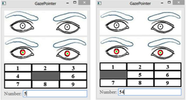
Fig. 1.   Setup for Eye Gaze Tracking [9]

Proposed system performance was analyzed in different sce-
narios and some limitations were defined, which are as follows.
User head should be at the same altitude as the web-cam.
Distance between user’s eyes and web-cam should be in the
range of 20-75 cm. This system can’t be used with glasses on,
lighting conditions should be good and head movements are
not allowed. Currently system is only tested for frontal faces.

            IV.    E YE G AZE T RACKING A LGORITHM
    Overview of Eye gaze tracking algorithm is presented in
Figure 2. It consists of three major modules: (i) Facial features
extraction; (ii) Eyes features detection and (iii) Point of Gaze
calculation.
    Algorithm presented in this paper performs operations on
grayscale images. Camera captures BGR or YCbCr color
space images, depending upon default settings. As a first step
BGR → grayscale color space conversion is performed. Basic
image pre-processing procedures are performed at each stage
of algorithm. Histogram equalization is applied on grayscale
images to normalize contrast in acquired image. It attempts to
equalize the image histogram by adjusting pixel intensities in
accordance with histogram [10]. For face detection, a machine
learning based approach is used, Object detection algorithm
proposed in [11]. This technique employs a Haar-features
based approach for object detection, which makes the rapid
and accurate object detection possible. Eye patch extraction
can also be performed using same object detection algorithm
described in [11]. For pupil detection, extracted eye patch
must be smoothed to avoid false detections. Pupil detection
technique being used is Hough Circle Transform (HCT) [12].
For image binarization, edge detection approach is used. Eye
region being used to trace the Test Area is to be detected, for
this purpose a simple calibration technique is designed, which
is explained later in this section. After features detection, a
simple Point of Gaze calculation algorithm is designed which
systematically interrelates the detected feature points to result
in a precise PoG calculation.

A. Facial Features Extraction
                                                                          Fig. 2.   Overview of GazePointer algorithm
    This paper intends to present an eye gaze tracking algo-
rithm and facial features detection i.e. face and eyes extraction
is an important task in this regard.

                                                                    155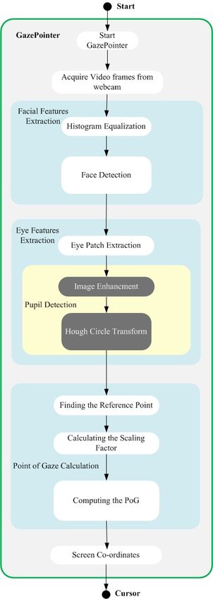
1) Histogram Equalization: Histogram equalization is a
technique for contrast normalization by adjusting image inten-
sities in accordance with image histogram [10]. It is a contrast
enhancement procedure which takes benefit of histogram data
and attempts to equalize the histogram. For performing facial
features detection, histogram equalization gives benefit of
better performance in terms of accuracy.
     2) Face and eye patch extraction: Face detection is a                     Fig. 3.   4-Point Simple Calibration
classification problem i.e. classify acquired image into face and
non-face regions. A rapid and robust object detection algorithm
is employed to perform face and eyes extraction, proposed                      a binary image. HCT is then applied on binarized image to
in [11]. It follows a machine learning based approach. Haar-                   compute Pupil points in both eyes.
features based classifiers can be trained for several objects                      2) Eye Corners Extraction: Eye corners are such an im-
detection i.e. face, eyes. These classifiers are trained for false             portant eye feature that a lot of information about eyes can be
positive and false negative samples as well. A set of simple                   extracted using eye corner locations. Once eye corner locations
features are obtained from training data. Haar- features are                   are known, they can be used to estimate eye width, eye height
calculated by the difference between dark-region and light-                    and most importantly this information can be used to locate
region pixel values. A threshold value is fixed at learning stage              center of eye.
i.e. feature is said to be present if difference value comes out
to be greater than the value fixed as threshold.                                   Another fact is established through several experiments that
                                                                               eye corners extraction is not suitable, to get to know about
    Face and eyes detection is a complex procedure, require                    movable area for iris in eye to trace the ‘Test Area’. For this
much computations to solve this classification problem. For                    purpose, after analysis it was concluded that computer is not
this purpose, acquired images are down-sampled, face is                        that intelligent to discover those boundary points in eye, user
detected and face co-ordinates are mapped to original image                    should feed some information at start and some procedures
using simple calculations. Same practice is exercised for eye                  must be implemented to use this information in intelligent
patch extraction to reduce the computation time; this approach                 way to extract features i.e. movable area for iris, center of
has proved to be effective in order to achieve real-time pro-                  eye etc. To meet this requirement, a simple 4-point calibration
cessing of the frame.                                                          technique is designed.
                                                                                   A 4-point calibration algorithm is designed for this system,
B. Eye Features Detection                                                      shown in Figure 3. Idea behind designing such calibration
                                                                               algorithm is, it can be helpful to calculate eye region which
    Eye gaze tracking is a complex problem; it needs to acquire
                                                                               will be used to scan the ‘Test Area’. This simple algorithm
a number of facial and eye features to compute Point of Gaze
                                                                               allows the user to look at all corner points in free mode. Here
(PoG). In this regard, first problem is to identify necessary and
                                                                               ‘free mode’ suggests that user is allowed to stay at a corner
sufficient eyes features which can result in an accurate PoG
                                                                               point for an arbitrary time duration. This idea helps the system
calculation. Two important eye features necessary to compute
                                                                               to reduce errors occurred due to erroneous pupil detections
PoG were identified, which are (i) Pupil and (ii) Eye Corners.
                                                                               during calibration.
This section presents the techniques utilized for these eye
features extraction.
                                                                               C. Point of Gaze Calculation Algorithm
     1) Pupil Detection: Pupil is the central and focusing part                    Point of gaze can be referred to as the point of interest
of eye, located at center of iris. Light enters into eye through               of user in ‘Test Area’. User’s point of interest i.e. PoG can
pupil, and finding the position of pupil is principal point of                 be calculated by extracting eye patch and some important eye
interest in proposed technique. Eye gaze projection is based                   features. Important eye features sufficient to calculate PoG has
upon the relative displacement of pupil from center of eye.                    been identified and discussed in earlier sections.
Pupil needs to be detected to project user’s eye gaze in the ‘Test
Area’. The first step in this regard, is to detect the iris from the               It is the most important and critical stage of algorithm as it
frames captured with web-cam, and then pupil can be found, as                  involves using already found feature points to calculate PoG.
it is situated at center of iris. Iris is a circular region and can be         This stage must effort to compensate the errors occurred at
detected using the very commonly used Hough circle transform                   detection stage.
technique [12]. Hough Circle Transform takes a binary image                        1) Finding the Reference Point: It is absolutely in-feasible
as an input and detects circle in it. The quality of the image                 to perform PoG calculations without a reference point. It will
needs to be good to extract every possible information from it.                be required to translate pupil movements in eyes into cursor
First, the input image is enhanced for good quality and then                   movements on screen. ‘Center of Eye’ can act as a desired
“Hough Circular transform” is applied on it.                                   candidate for reference point. Eye’s movable region has already
     To enhance image, smoothing is applied which in-effect                    been computed during calibration stage, a simple averaging of
reduces noise. For this purpose, grayscale image is passed                     x and y co-ordinates can result in Center of Eye calculation.
through Gaussian blurring filter. The technique used for iris                  This concept is illustrated in Equation 1 and Equation 2.
detection is ‘Hough Circle Transform’. Canny edge detection                                      T opRightCornerx + T opLef tCornerx
filter [10] is applied on enhanced grayscale image to compute                      COEx =                                                    (1)
                                                                                                                  2

                                                                         156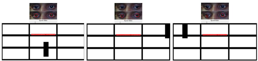
T opRightCornery + BottomRightCornery
  COEy =
                               2
                                                           (2)
    Where, COEx and COEy denote x and y coordi-
nates of center point of eye’s movable region respectively.
T opRightCorner, T opLef tCorner, BottomRightCorner
and BottomLef tCorner construct a rectangular region which
represent eye’s movable region.
    2) Calculating the Scaling Factor: In this step the cursor
movements and pupil movements were interrelated i.e. it was
to be found that how many pixels a cursor will traverse for
a single pixel movement of the pupil. For this calculation,
width and height of eyes were associated with the width and
height of the screen. Screen width and height is constant, but
eye’s movable region width and height is subject to change
in different scenarios. Eye’s movable region width and height
can be computed using Equation 3 and Equation 4.
      weye = T opLef tCornerx − T opRightCornerx           (3)
                                                                       Fig. 4.   Computing Point of Gaze using Reference Point
  heye = T opRightCornery − BottomRightCornery             (4)
                                                                                   TABLE I.        E XPERIMENT 1 ACCURACY R ESULTS
   Where, weye and heye represent width and height of eye’s                                    Extracted Features     Accuracy
movable region respectively. Now scaling factor is to be                                       Face Detection           100%
computed for x and y coordinates with help of Equation 5                                       Eye Patch Extraction     100%
and Equation 6.                                                                                Pupil Detection           87%
                            wscreen
                     Rx =                               (5)
                             weye
                                                                                         V.    EXPERIMENT RESULTS
                            hscreen
                       Ry =                                (6)             Two experiment setups were designed to test the developed
                             heye
                                                                       system.
   Where, wscreen and hscreen denote width and height of
                                                                       A. Experiment 1: GazePointer GUI
‘Test Area’. Rx and Ry represent scaling factor for x and y
coordinates.                                                               A ‘Graphical User Interface’ is designed to demonstrate
                                                                       the results. First area show the extracted eye-patch from the
    3) Computing the PoG: This is the final step of PoG                captured frames and second area indicates HCT results. The
calculation as well as GazePointer algorithm. This stage will          portion under it represents the ‘Test Area’ for movement of
realize the significance of reference point. It translates the         mouse pointer. A small GazePointer is shown in the Figure 4
pupil movements in eyes into cursor movements in ‘Test Area’.          which shows the projection of eye movements.
Taking assumption that reference point in eye corresponds to
center point in ‘Test Area’, pupil movements can be simply                 1) Experiment 1 Results: In this section, results of exper-
translated into cursor movements using Equation 7 and Equa-            iment 1 are presented. Accuracy results of experiment 1 are
tion 8.                                                                presented in Table I. Overall accuracy of 87% is being reported
                          wscreen
                 P oGx =           + Rx × rx               (7)         for experiment 1. Experiment 1 efficiency results are presented
                             2                                         in Table II. Overall time for processing of 43 mS per frame is
                          hscreen                                      being reported, which means GazePointer system works at 23
                P oGx =           + Ry × ry                (8)         fps.
                             2
                                                                           2) Experiment 1 Results Discussion: Face detection pro-
    Where, P oGx and P oGy represent x and y coordinates of            vided satisfactory results. Accuracy did not drop with changing
Point of Gaze respectively and rx denotes pupil distance in x          lighting conditions, backgrounds, and distance. This imple-
direction from reference point and ry denotes pupil distance           mentation detects frontal faces only. Its accuracy remained
in y direction from reference point and they can be computed           100% when tested on a limited dataset of 223 frames. A few
by using Equation 9 and Equation 10.
                                                                                   TABLE II.       E XPERIMENT 1 ACCURACY R ESULTS
                    rx = COIx − COEx                       (9)
                                                                                        Extracted Features       Processing Time (mS)
                    ry = COIy − COEy                     (10)                           Face Detection                  13-15
                                                                                        Eye Patch Extraction            10-15

    Where, COI represents pupil location. Figure 4 illustrates                          Pupil Detection                  6-10
                                                                                        PoG Computation                  2-3
this procedure.

                                                                 157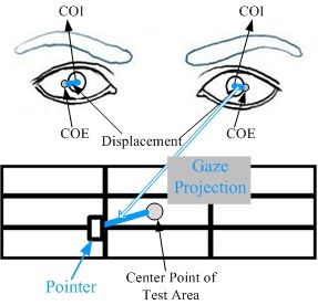
Fig. 5. PoG calculation results in different frames
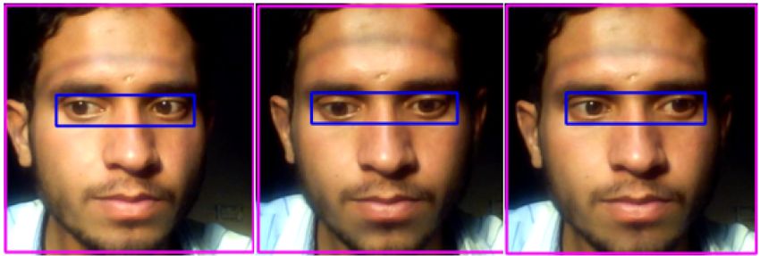
Fig. 6. Face and Eyes Detection Results
Fig. 9. Experiment 2 Results in different frames
Fig. 7. Extracted Eye Patch in different frames
TABLE III. E XPERIMENT 2 ACCURACY R ESULTS
samples of face detection results are presented in Figure 6. Extracted Features Accuracy
GazePointer is assumed to be a system working with real- Pupil Detection 100%
time constraints. Captured frames were down sampled 5 times PoG Computation 100%
to reduce the computation time. Before re-sizing, it took 500-
600 mS per frame and it reduced to only 13-15 mS per frame.
B. Experiment 2: Test Bench
Eyes detection implementation was done accurately in al-
most every case when face was detected. This implementation A simple Test Bench model was designed to test the
was also tested on a limited dataset of 223 frames and it accuracy of this system. Artificial eyes instead of human eyes
resulted in 100% accuracy. Eyes detection results are given in were used. Application prompts user to input a number. Iris
Figure 7. This implementation resulted in a large computation moves in accordance with the number entered. Algorithm
time. The computation time was reduced by limiting the region processes these iris movements and projects the eye gaze in
of interest to detected face only. Then this face region was ‘Test Area’.
down sampled 2 times. Computation time was reduced to 10- 1) Experiment 2 Results: Accuracy results of experiment 2
15 mS per frame after modifying the implementation. are presented in Table III. Overall accuracy of 100% is being
HCT implementation resulted in a few mS processing reported for experiment 2. A few results from experiment 2
time. Initial algorithm resulted in lots of false detections. It are shown in Figure 9. Time efficiency results of experiment
resulted in accuracy of 80% when tested on a limited dataset 2 are shown in Table IV. Overall processing time of 13 mS
of 223 frames. Pupil detection results are given in Figure per frame is being reported for experiment 2.
8. The rate of false detections was decreased by applying a
threshold between previous frame pupil location and present VI. CONCLUSION
frame pupil location. Thus, accuracy improved to 87%. Point
In this paper a computer vision algorithms based solution is
of Gaze Calculation resulted in satisfactory results when tested
implemented. An attempt has been made towards development
on a limited dataset PoG calculation results are presented in
of low cost, real-time solution for eye gaze tracking. There
Figure 5. Projections followed user’s eye-gaze. False detections
are many applications of eye gaze tracking, for instance in
were involved because pupil detection results were not 100%
HCI, appliances control, usability studies and in advertising
accurate.
TABLE IV. E XPERIMENT 2 E FFICIENCY R ESULTS
Extracted Features Processing Time (mS)
Pupil Detection 6-10
Fig. 8. Pupil detection in different frames PoG Computation 2-3
158effectiveness. Accuracy for features extraction algorithms de- [12] C. Kimme, D. Ballard, and J. Sklansky, “Finding circles by an array
pends upon image quality and lighting conditions. Algorithm of accumulators,” in Communications of the Association for Computing
Machinery, 1975, pp. 120122.
performance drops down in poor lighting environment. Com-
puter Vision algorithms are employed for features detection [13] H. Hua, P. Krishnaswamy, and J. P. Rolland, “Video-based eyetracking
methods and algorithms in head-mounted displays,” Optics Express, vol.
and they don’t perform well in bad lighting. PoG is accurately 1, no. 10, pp. 4328-4350, 2006.
calculated provided detections are correct. Pointer size is large
due to low web-cam resolution and small ‘Test Area’ size.
To improve the projection results, image quality must
be enhanced. Better image quality would improve accuracy
of computer vision algorithms. Sophisticated Pre-Processing
algorithms should be introduced to compensate lighting vari-
ations and web-cam resolution should also be increased to
decrease the pointer size. A feature describing head-posture
must also be introduced, it will allow the user to move-
freely while interacting with system. Introducing the concept
of gaze estimation along with gaze projection will be beneficial
because it will improve gaze projections drastically. The idea
of gaze estimation promises to learn from usage statistics
and infer gaze projections. Particle Filters can be used to
implement gaze estimation because they are quite simple and
has resemblance with problem of gaze estimation.
ACKNOWLEDGMENT
The authors would like to thank Mr. Muhammad Adnan
Siddique for his continuous guidance during this research
work.
R EFERENCES
[1] Alex Poole and Linden J. Ball, “Eye Tracking in Human-Computer In-
teraction and Usability Research: Current Status and Future Prospects,”
in Encyclopedia of Human Computer Interaction (30 December 2005)
Key: citeulike:3431568, 2006, pp. 211-219.
[2] D. H. Yoo, J. H. Kim, B. R. Lee, and M. J. Chung, “Non-contact
Eye Gaze Tracking System by Mapping of Corneal Reflections,” in
Fifth IEEE International Conference on Automatic Face and Gesture
Recognition (FGR02), 2002, pp. 94-99.
[3] Rafael Barea, Luciano Boquete, Manuel Mazo, and Elena Lpez, “Sys-
tem for assisted mobility using eye movements based on electrooculog-
raphy,” IEEE TRANSACTIONS ON NEURAL SYSTEMS AND REHA-
BILITATION ENGINEERING, vol. 10, no. 4, pp. 209-217, DECEMBER
2002.
[4] H. Singh and J. Singh, “A Review on Electrooculography,” International
Journal of Advanced Engineering Technology, vol. III, no. IV, 2012.
[5] K. Irie, B. A. Wilson, and R. D. Jones, “A laser-based eye-tracking
system,” Behavior Research Methods, Instruments, & Computers, vol.
34, no. 4, pp. 561-572, 2002.
[6] P Ballard and George C. Stockman, “Computer operation via face
orientation,” in Pattern Recognition, 1992. Vol.I. Conference A: Com-
puter Vision and Applications, Proceedings., 11th IAPR International
Conference on, 1992, pp. 407-410.
[7] T. Horprasert, Y. Yacoob, and L.S. Davis, “Computing 3-D head
orientation from a monocular image sequence,” in Second International
Conference on Automatic Face and Gesture Recognition, 1996, pp. 242-
247.
[8] K. Arai and M. Yamaura, “Computer Input with Human Eyes-Only
Using Two Purkinje Images Which Works in a Real-Time Basis without
Calibration,” CSC Journals, vol. 1, no. 3, pp. 71-82, 2010.
[9] D. Back, “Neural Network Gaze Tracking using Web Camera.,”
Linkping University, MS Thesis 2005.
[10] R. Gonzalez and R. Woods, Digital Image Processing, 3rd ed.: Pearson
Education, 2009.
[11] P. Viola and M. Jones, “Rapid Object Detection using a Boosted
Cascade of Simple Features,” in COMPUTER VISION AND PATTERN
RECOGNITION, 2001.
159You can also read