Generative Adversarial Networks with Physical Evaluators for Spray Simulation of Pintle Injector - arXiv.org
←
→
Page content transcription
If your browser does not render page correctly, please read the page content below
Generative Adversarial Networks with Physical
                                                       Evaluators for Spray Simulation of Pintle Injector

                                                               Hao Maa , Botao Zhangb , Chi Zhangc , Oskar J. Haidna,∗
arXiv:2101.01217v1 [physics.flu-dyn] 27 Dec 2020

                                                   a Department  of Aerospace and Geodesy, Technical University of Munich, 85748 Garching,
                                                                                             Germany
                                                       b Key Laboratory for Liquid Rocket Engine Technology, Xi’an Aerospace Propulsion

                                                                                 Institute, 710100 Xi’an, China
                                                   c Department of Mechanical Engineering, Technical University of Munich, 85748 Garching,

                                                                                             Germany

                                                   Abstract

                                                   Due to the adjustable geometry, pintle injectors are specially suitable for the liq-
                                                   uid rocket engines which require a widely throttleable range. While applying the
                                                   conventional computational fluid dynamics approaches to simulate the complex
                                                   spray phenomena in the whole range still remains to be a great challenge. In
                                                   this paper, a novel deep learning approach used to simulate instantaneous spray
                                                   fields under continuous operating conditions is explored. Based on one specific
                                                   type of neural networks and the idea of physics constraint, a Generative Ad-
                                                   versarial Networks with Physics Evaluators (GAN-PE) framework is proposed.
                                                   The geometry design and mass flux information are embedded as the inputs.
                                                   After the adversarial training between the generator and discriminator, the gen-
                                                   erated field solutions are fed into the two physics evaluators. In this framework,
                                                   mass conversation evaluator is designed to improve the training robustness and
                                                   convergence. And the spray angle evaluator, which is composed of a down-
                                                   sampling CNN and theoretical model, guides the networks generating the spray
                                                   solutions more according with the injection conditions. The characterization of
                                                   the simulated spray, including the spray morphology, droplet distribution and
                                                   spray angle, is well predicted. The work suggests a great potential of the prior

                                                     ∗ Corresponding author. Tel.:.+49 89 289 16084.
                                                      Email addresses: hao.ma@tum.de (Hao Ma), 2018zhangbotao@mail.nwpu.edu.cn (Botao
                                                   Zhang), c.zhang@tum.de (Chi Zhang), oskar.haidn@tum.de (Oskar J. Haidn )

                                                   Preprint submitted to X. X. X                                          January 6, 2021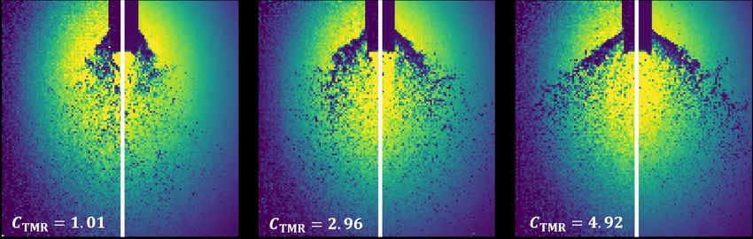
physics knowledge employment in the simulation of instantaneous flow fields.
Keywords: Deep learning, Physics-informed neural networks, Generative
adversarial networks, Spray simulation

                                         2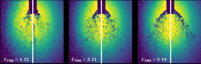
1. Introduction

   Due to a wider throttling range and greater combustion stability, pintle
injectors are specially suitable for the liquid rocket engines that require deep,
fast, and safe throttling[1, 2], such as the descent propulsion system in Apollo
program[3] and the reusable Merlin engine of SpaceX[4].
   In the practical throttleable engine applications, the pintle is movable to al-
ter the injection area so that the mass flow rate of the injected propellants can be
varied continuously according to the economical and safe thrust curve in a given
situation[5]. However, in the previous spray simulations of pintle injectors, the
changes were only considered under discrete condition combinations over a lim-
ited amount of select operating points[6, 7, 8]. For the traditional discrete meth-
ods they used, simulations have to be conducted repeatedly to varies the oper-
ating conditions and the computational cost becomes prohibitively expensive[9].
Innovations for the spray simulation of the pintle injector are needed to address
this issue.
   Contrarily, machine learning approach, especially the Neural Networks(NN),
has demonstrated its efficiency to predict the flow fields under different condi-
tions with a single surrogate model[10]. The previous researches on flow field
prediction using NN are mainly focused on the data-driven method. Besides
the indirect way using closure model[11, 12], the field solution can also be di-
rectly obtained from the network model which is trained with a large number
of samples[13, 14, 10, 15]. However, some predictive results obtained by data-
driven methods may still exhibit considerable errors against physics laws or
operating conditions[13, 16, 17]. Besides, In some sparse data regime, some
machine learning techniques are lacking robustness and fail to provide guar-
antees of convergence[18]. For the purpose of remedying the above mentioned
shortcomings of data-driven methods, the physics-driven/informed methods are
proposed recently[19]. By providing physics information, NN are able to di-
rectly obtain field solutions which obey physical laws and operating conditions.
In these work, Partial Differential Equations (PDEs) was employed in the loss

                                         3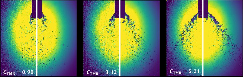
function to explicitly constrain the network training[20, 21].
   In the state-of-the-art neural networks methods, Generative Adversarial Net-
works (GANs) proposed by Goodfellow et al.[22], are efficient to generate the
instantaneous flow fields[23, 24]. In spite of the impressive performance for un-
supervised learning tasks, the quality of generated solutions by GANs is still
limited for some realistic tasks[25]. Besides, as shown in the training results
later, the transient nature of the spray injection and liquid sheet break results
in the extreme difficulty of usual networks to qualify the place and intensity of
dominating characterizations.
   In this paper, based on one specific type of GAN and the idea of physics
constraint, a novel Generative Adversarial Networks with Physical Evaluators
(GAN-PE) framework is proposed. By introduction of mass conversation and
spray angle model as the two evaluators, this framework has a better training
convergence and predictive accuracy. The trained model is able to simulate the
macroscopic morphology and characterization of the instantaneous flow fields
under different conditions. This paper is organized as follows. We firstly intro-
duce the experimental settings and data set acquisition. Secondly, the archi-
tecture of GAN-PE and the detailed parts are described. Then, the learning
results of numerical experiments are presented for validation. Finally, conclusion
is drawn.

2. Data Set from Experiments

   Our training data are extracted from the spray experimental results of the
pintle injectors.

2.1. Experimental facilities

   The non-reactive cold experiments were conducted at atmospheric pressure.
The dry air is used as the stimulant for axial flows and filtered water as the
stimulant for radial flows. The schematic of experimental facilities are shown
in Figure 1a. A back-lighting photography technique is used for instantaneous

                                        4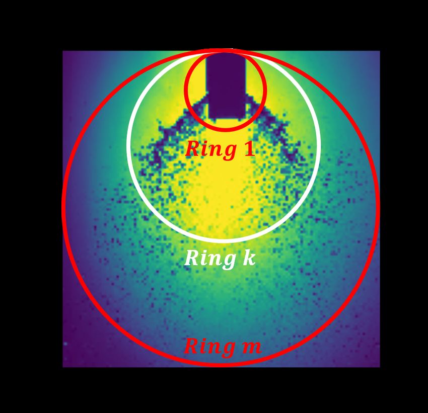
spray image visualization. The image acquisition system consists of an LED
light source, a high-speed camera and a computer. The exposure time is 10 µs
and frame rate is 50k fps.

                                                                                     Liquid inlet

                                                                 Replaceable
                                                                 Liquid jet parts

                                                     Gas inlet                                                       Gas inlet

                                                                 Centre body
                                                                                                    Replaceable
                                                                                                    gas sheet part
                                                                  Gas sheet outlet
                                                                                               Liquid jet outlet

  (a) Schematic of the experimental facilities                              (b) Pintle injector

Figure 1: Experimental facilities and devices. (a)Schematic of the experimental facilities.
The test bench is composed of gas-liquid pintle injector, propellants feed system and control
system. Spray visualization system includes a LED lamp and a high speed camera. (b)Gas-
liquid pintle injector within manifold. The experimental injector consists of a gas manifold,
a replaceable liquid manifold, a replaceable axial gas sheet adjustment annular, a central
cylinder and a sleeve. In order to facilitate the optical observation about the spray angle, two
symmetrical radial liquid jet orifices are designed on the central cylinder.

    The detailed gas-liquid pintle injector is featured in Figure 1b. In order to
study the influence of the momentum ratio on the spray angle, the experimental
device is designed to use the replaceable parts. In the experiment, the height of
the radial liquid jet outlet and the thickness of the axial gas sheet are adjusted
by changing the height of the sleeve and the axial gap distance, respectively.
When the liquid propellant is injected radially from the two sides of the pintle
end through the manifold, the liquid columns is formed. These columns are
broken by the axially gas propellant injection from the gap cling to the pintle.
Finally, due to an impingement and collision, the liquid columns break and form
a plane conical spray like a hollow-cone atomizer. This design induces vigorous
mixing of the gaseous and liquid propellants which yields a high combustion

                                               5
efficiency[26]

2.2. Data set acquisition

   The spray experiments are carried out with the throttling level Lt of 40% ∼
80%. Lt is varied by the linear adjustment of the height of radial liquid jet
outlet and the thickness of axial gas sheet. The radial liquid jet outlet height at
throttling levels of 40%, 60%, and 80% are 2mm, 3mm and 4mm, respectively.
When Lt is fixed, the height of the radial liquid jet outlet is fixed and equal
to the thickness of the axial gas sheet. Table 1 shows the operating conditions
of the experimental campaign and the corresponding key specifications of the
pintle injector.

Table 1: Experimental operating conditions. Lopen and Tgs are injector opening distance and
gas sheet thickness respectively. mg and ml are the mass flow rate of gaseous and liquid
propellant respectively. CTMR is the momentum ratio of the two propellants.

     Lt     Lopen (mm)      Tgs (mm)      mg (g/s)        ml (g/s)            CTMR

    80%            4.0           4.0       22.17       18.55 ∼ 40.54      1.01 ∼ 4.92
    60%            3.0           3.0        15.7       14.85 ∼ 30.46      1.22 ∼ 5.14
    40%            2.0           2.0       29.85        8.85 ∼ 20.45      0.98 ∼ 5.21

                 (a) Raw image                                 (b) Average

           Figure 2: Data acquisition. The resolution of the images is 640 × 480.

                                             6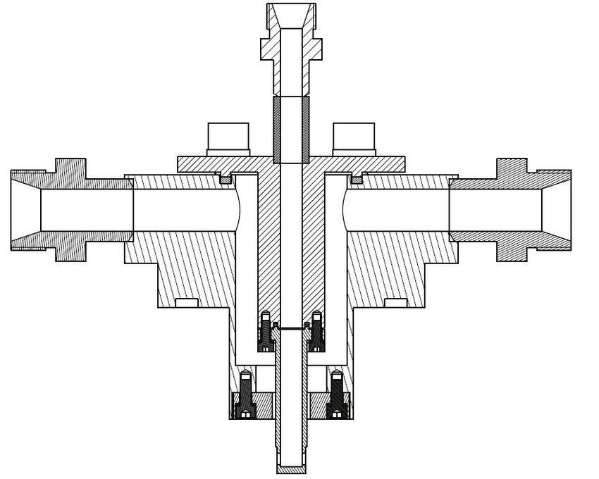
As shown in Figure 2, to measure the spray angle, the spray images obtained
in the experiment are post-processed to clarify the spray boundary. The average
of 10 images is used to measure the spray angle manually. Using this setup, the
time-averaged images of sprays are obtained and the spray angles, defined as
      1
θ =   2 (θ1   + θ2 ), are manually-measured. Then, the average images and the
corresponding spray angles are used to train the spray angle estimator later.
   The resolutions of the instantaneous spray image are 640 × 480. In order
to reduce the training cost, the images are interpolated to the images with a
resolution of 128 × 128. While the measured angle values, which represented
the nature of the spray phenomenon, are fixed in spite of the image scaling.

3. Methodology

3.1. Overview

   Here, a Generative Adversarial Networks with physical evaluators (GAN-PE)
framework is proposed. As shown in Figure 3, The GAN-PE is composed of 4
parts, Generator (G), Discriminator (D) and two physical evaluators. After
the initial field solution is generated by G, there are three parts are employed to
guarantee the output being an accurate field solution. GANs is the base of the
proposed networks framework, the G captures the real spray data distribution
which is corresponding to the operation conditions, and the D estimates the
probability that a condition-sample pair came from the training data rather than
G. There are also two evaluator designed to improve the performance of GANs.
The first Mass Conservation Evaluator (EMC ) is used to improve the generation
robustness and training convergence. The second Spray Angle Evaluator (ESA )
is used to improve the predicting accuracy in the specific operating conditions.
Fed with the outputs from G, the losses of D, EMC and ESA are calculated
respectively. After that, the backpropagation is applied to adjust the U-net
CNN of G to generate a new spray field that more satisfies the conditions and
prier physics knowledge. After enough iterations, the network will be able to
generate ‘correct’ spray field.

                                        7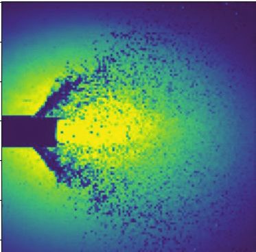
Parameters Updated
Discriminator
ْ
Inputs Targets
Real/Fake
ْ
Generator
Evaluator-MC
ٓ
݉௨௧ െ ݉௩
Inputs Outputs
Evaluator-SA
ߠᇱ െ ߠ
Spray Angle Model
Parameters Updated
Figure 3: Schematic of the proposed networks framework. With the operating conditions, the
U-net generator outputs a field solution of the spray. Then the outputs will be transferred
to discriminator, mass conservation evaluator and spray angle evaluator. With the input-
target pair and input-output pair, the discriminator is trained to distinguish the real and
fake images. The mass conservation evaluator calculates the ring error between output and
the corresponding average target. The spray angle estimator judges the angle value from
the output and then compare it with theoretical one. Eventually the discriminator, mass
conservation and spray angle losses are utilized to update the generator by backpropagation.
8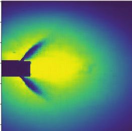
3.2. GAN

Generator
   From inputs towards outputs, the network of G consists of two parts: encod-
ing and decoding[27] . In the encoding process, the operating conditions Lopen ,
Tgs , mg and ml are resized as four matrices for progressively convolutional down-
sampling with corresponding kernels. By this way, the matrices with a size of
128 × 128 is reduced into one liner data pool consisting of 512 neurons. Then
the decoding part works in an opposite way, which can be regarded as an inverse
convolutional process mirroring the behavior of the encoding part. Along with
the increase of spatial resolution, the spray fields are reconstructed basing on
the data pool by up-sampling operations. In addition, there are the concatena-
tion of the feature channels between encoding and decoding. More details of the
U-net architecture and convolutional block, including active function, pooling
and dropout, are referred to Ref. [21].
   The weighted loss function considering the following discriminator and eval-
uators is written as

                  L(D, EMC , ESA ) = LD + αLEMC + βLESA ,                     (1)

where LD , LEMC and LESA are the loss terms that calculated by D, EMC and
ESA respectively. Also, α and β are the constant hyperparameters which are
tuned to adapt the scales of these loss terms. After proper training, the gener-
ator is able to map a spray sample from a random uniform distribution to the
desired distribution which obey the physical knowledge and conditions.
Discriminator
   Then D is used to feed the possibility of that samples come from the training
rather than generation distribution back to G. We use Least Squares Gen-
erative Adversarial Networks (LSGANs) settings to train the D and the G
simultaneously[28]. This special type of GANs helps to remedy the gradients
vanishing by using the least square loss function instead of the sigmoid cross
entropy loss function[29].

                                          9
Here, D is modified by the encoder of the G, which means the generations
are dawn-sampling by the re-convolutional calculation so that the spray field
information are concluded into the linear 1-D tensor. And then this 1-D data
pool will be used to be trained to maximize the probability of assigning the cor-
rect label (real/fake) to both training targets and generating solutions. Similar
with the work in Ref.[30], we use the input-output pair to feed D instead of only
G’s outputs in the random image generation tasks. The operating conditions
and the outputs are concatenated as the different feature channels in a unique
4-D data tensor. By this way, the D helps to judge whether the outputs accord
with the corresponding conditions, not only having right spray morphology.
The loss functions for LSGANs are defined as
1 1
min VGAN (D) = Ex∼pdata (x) [(D(x) − b)2 ] + Ez∼pz (z) [(D(G(z)) − a)2 ]
D 2 2
(2)
1 2
min VGAN (G) = Ez∼pz (z) [(D(G(z)) − c) ],
G 2
where x is the training data and z is the input variables. Also, a and b are the
labels for fake data and real data respectively, and c denotes the possibility that
G wants D to believe for fake data. Here, we apply a = 0 and b = c = 1. So,
LD is equal to the second part of Equation (2).
3.3. Evaluators
Mass conservation evaluator
As shown in Figure 4, we assume that there are a few rings with different
diameters that are tangent at the middle point of the upper boundary in both
generating images and the average images. Following the definition of “L1loss”
which is widely used in machine learning community, we define a mass conser-
vation loss here. The difference is that the former measures the sum of absolute
error between each element in the generation and target[31], but ours is calcu-
lating firstly a gray value summation of every element in one concerning ring
and then the summation of absolute error between the corresponding rings in
the generation and target. The idea is from that the spray phenomenon obeys
mass conservation law, i.e. the mass fluxes of droplets through one specific ring
10in every instantaneous frame are equivalent. Here, the “mass flux” is a broader
concept which also involves the background shadow.
(a) Generated images (b) Average target
Figure 4: Mass Conservation. The resolution of the images is 128 × 128.
The mass conservation error, i.e. the loss term from EMC , is defined as
Xm X n Xn
xi − yj E ≥ Ethr
LEMC = k=1 i=1 j=1
k
, (3)
0 E < Ethr
where x and y are the gray values in generated images and average targets
respectively. Also, m is the amount of the concerning rings and n is the amount
of data points in one concerning rings in the matrix. E is the error between the
output and average matrix and defined as
N
X
E= |xi − yi | , (4)
i=1
where N is the amount of all the data points in the matrix. To improve the
generation randomness and in view of the error caused by light transmission and
reflection, loss threshold Ethr is introduced herein. Once the loss is less than the
threshold, this loss term will be ignored.
Spray angle evaluator
This evaluator is composed of two parts, one is the theoretical model of
11spray angle, the another is a CNN encoder to estimate the spray angles from
the generated field solutions.
Propellant 2
ࡸܖ܍ܘܗ
࣐
ࡴ
ࣂ
Figure 5: Spray angle model
The schematic diagram of the theoretical model of spray angle is shown in
Figure 5. Several basic hypotheses must be declared before carrying out the
theoretical analysis. (a). An element of fluid emerging from the jet exit is as-
sumed to have the constant length and width equal to the jet exit length L and
width W , as it moves along the trajectory. (b). Liquid jet deformation, evap-
oration and droplet dispersion are ignored. (c). As the fluid element exits the
slot, it has an initial velocity and an initial angle equal to the central propellant
deflection angle ϕ. (d). The aerodynamic force is assumed to be parallel to
the gas sheet flow direction, and the movement direction of the fluid element is
deflected. (e). The spray angle is assumed to be equal to the slope of the liquid
jet at the thickness point of the gas film. (f). Surface tension, gravity, friction,
heat transfer and phase change are ignored.
The axial momentum equation can be written as follows:
1 2 du
ρg (ug − ul cosϕ) WH = ρl WLopen H , (5)
2 dt
12so that integration of the axial momentum equation with respect to time is
2
1 ρg (ug − ul cosϕ)
ul = t + ul cosϕ, (6)
2 ρl Lopen
du
with ul = dt , a second integration with respect to time is
2 2
1 ρg (ug − ul cosϕ) y yul cosϕ
x= + . (7)
4 ρl Lopen ul sinϕ ul sinϕ
For the collision between the gas sheet and the rectangular liquid jet, the mo-
mentum ratio is
ṁl vl ρl vl2 Al ρl vl2 W Lopen ρl vl2 Lopen
CTMR = = 2
= 2
= . (8)
ṁg vg ρ g v g Ag ρg vg WH ρg vg2 H
Equation 7 could then be expressed in terms of the momentum ratio CTMR as
follows 2
1 ul cosθ cosθ
x= 1− y2 + y, (9)
4CTMR Hsin2 θ ug sinθ
where the slope of the liquid jet θ at the thickness of the gas sheet could be
written as 2
◦ 1 ul cosϕ cosϕ
θ = 90 1− + . (10)
2CTMR sin2 ϕ ug sinϕ
The theoretical model assumes that the liquid jet does not deform, but in
reality it will deform under aerodynamic forces, which results in a reduction of
the effective momentum of the liquid jet. Therefore, the liquid jet deformation
factor γ, which is obtained through the experimental results, is introduced to
modify the spray angle theoretical model. The Eq(10) is rewritten as
2 !
1 ul cosϕ cosϕ
θ = γ 90◦ 1− + . (11)
2CTMR sin2 ϕ ug sinϕ
In the field of medical image analysis, the machine learning approach, es-
pecially the deep neural networks, has been employed for automated scoliosis
assessment[32]. In these work, the X-ray images are fed into the neural networks
estimator and the spinal Cobb angles are obtained[33, 34]. Similarly, inside the
ESA , there is a well-trained spray angle estimator to output the angle values
from the predictive images. The architecture of this CNN encoder is like the D,
except added one liner layer in the end to output the estimated spray angle θ0 .
13The loss term from ESA is calculated as
LESA = θ0 − θ. (12)
4. Results
4.1. Model validation
(a) Experiment (b) CNN (c) Original GAN
Figure 6: Comparison of CNN generator and original GAN. Lopen = Tgs = 4mm, ml =
35.81g/s, mg = 22.17g/s .
Figure 6 shows the generated results in one typical operating condition of
CNN generator and original GAN. The L1 loss used by CNN generator compares
the difference between the generations and targets. This absolute error loss
performs very well in some steady or mean state field prediction tasks, such
as the work in Ref. [17, 21]. However, when the training cases have a multi-
modal distribution, this loss will fail down. In our spray field prediction task,
although the morphology under one specific operation condition are similar, but
the detailed droplet distributions are distinguishable. So the spray field solution
actually has many possibilities and the prediction in every iterative step should
be one of them. But the L1 loss averages all the possibilities and produces a very
blurry average image instead. However, the discriminator in GANs which can
be regarded as the loss of generator is not an explicit loss function. Instead of
the pixel-wise loss, D is an approximation loss and it denotes the overall spray
morphology which discriminates between the real and fake data distributions.
14In the training process of GANs, the generator and discriminator have to
been balanced trained and the convergence is often an unstable state. For the
spray simulation task, the discriminator have difficulties to capture the detailed
feature of the small droplets.
The LD has a possibility of becoming less meaningful through the training
process. And the G will update itself based on the random feedback and the
quality of generation may collapse. The G outputs low-quality images through
many epochs, some of them shows faint spray pattern in the background but
are easily identified as fake. It will be very easy for the discriminator to distin-
guish the targets and generation so the values of the loss from D drop to zero
rapidly. The comparison of generated spray images from different framework
demonstrates the superior performance of the mass conservation evaluator as
shown in Figure 7. In some generated images, the background is not agree with
the real target, the introduction of the LEMC helps G identifying the position
and intensity of the droplet as well as the background shadow.
In our framework, when getting the predicted spray field, all the output
matrices in one batch will be averaged to one image. Then this average image
will be used to feed the down-sampling CNN to obtain the spray angle of this
batch. Here, we use the average images from experiments as test samples for the
validation of the spray angle estimator. Table 2 shows the comparison of spray
angles obtained by Manual Measurements (MM) and CNN estimator. With the
increase of CTMR , the deviations between the two tend to be smaller. The error
of all the test cases are less than 5.8%.
After this CNN estimator being trained, it only takes some milliseconds to
output a angle value which is according to the operating conditions of this batch.
Then, the estimated value is employed in the LESA to update G. Due to the
quick decrease in the beginning of the training, this error is no longer affect the
G, only except for the generated solutions with a paradoxical angle.
15(a) Experiment (b) GAN with EMC
(c) Original GAN
Figure 7: The comparison between the results of with or without EMC .
Table 2: Spray angle estimation by manual measurement and CNN.
Lt = 80% Lt = 60% Lt = 40%
CTMR
MM CNN Error(%) MM CNN Error(%) MM CNN Error(%)
0.52 ∼ 0.56 31.27 29.70 5.0 29.31 28.04 4.3 26.05 27.57 5.8
0.79 ∼ 0.86 36.32 35.10 3.4 33.12 34.54 4.3 31.59 32.61 3.2
0.98 ∼ 1.22 40.67 41.98 3.2 34.89 35.60 2.0 34.67 35.15 1.4
1.29 ∼ 1.34 41.98 40.37 -3.8 39.21 39.34 0.3 36.36 37.0 1.75
1.50 ∼ 1.70 44.37 45.99 3.7 42.87 43.37 1.2 39.43 38.08 -3.4
1.98 ∼ 2.04 45.28 47.45 4.8 43.43 44.62 2.7 41.01 41.47 1.1
2.56 ∼ 2.69 49.88 49.43 -0.9 47.34 45.46 -4.0 44.64 44.39 -0.6
2.90 ∼ 3.22 50.36 50.02 -0.7 48.13 47.07 -2.2 44.98 45.64 1.5
3.33 ∼ 3.39 51.32 52.92 3.1 48.12 48.75 1.3 46.01 46.64 1.4
3.83 ∼ 4.12 52.18 52.55 0.7 48.84 51.09 4.6 447.64 48.98 2.8
4.50 ∼ 4.88 54.39 53.92 -0.9 49.34 50.57 2.5 48.80 49.60 1.7
5.12 54.55 55.96 2.6 49.41 50.75 2.7 – – –
164.2. Predictions
Literature shown that the macroscopic morphology study is important to
characterize a spray[35]. Here, the simulated spray morphology is analyzed and
compared with the experimental results.
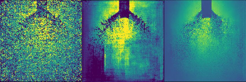
(a) Lt = 80%
(b) Lt = 60%
(c) Lt = 40%
Figure 8: Simulated and experimental spray morphology under different throttling level and
momentum ratio. The left half part is the simulated spray obtained by GAN-PE, and the
right half part is the corresponding experimental high-speed image with the same size scale.
17Figure 8 compares the simulated and experimental spray morphology under
different operating conditions. The typical spray morphology, i.e. liquid column
formation, breakup of the column, lateral expansion of the spray, can be clearly
noted. The generated spray field shows that the droplets experience a size
reduction before approaching a uniform tiny size distribution because of the
impingement and collision. As the figure shown, the generated spray is fairly
comparable with the experimental results, meanwhile the hollow-cone-shaped
profiles with a specific spray angle are well reproduced. For those cases that
are out of the training domain, the last column in the figure, the generation is
also present a similar good quality compared with those inside. Imperfectly, the
background still represents grainy and the values of adjacent data points are
not as continuous as those in the real images. However, all in all, the simulation
succeeds to report the macroscopical morphology of the spray.
Figure 9 shows the curves of the spray angle versus momentum ratio at
different throttling levels, it can be observed that the GAN-PE results coincide
with the experimental results well in a wide momentum ration range. According
to theoretical analysis which has been explained in Section 3.3, the spray angle
is mainly determined by the momentum ratio, and the simulated solutions also
represent it. For the cases which under a small momentum ratio, due to the
difficulties to estimate the small spray angle, the predicted ones have a relatively
bigger errors and the values of different throttling levels are close to each other.
For the test cases which are not in the learning domain, the results have a small
deviation and all the predicted angle values are less than the manually-measured
ones. It is because these test cases are not constrained by the targets so the
prediction have a trend to approach the mean value of the adjacent operating
points which is happened to be larger.
5. Conclusion
In this paper, we proposed a novel deep learning framework constrained
by physical evaluators to directly predict spray solutions based on generative
1855
50
45
θ(o)
40
35 GAN-PE:Lt=80%
GAN-PE:Lt=60%
GAN-PE:Lt=40%
30 Exp:Lt=80%
Exp:Lt=60%
Exp:Lt=40%
25
1 2 3 4 5
CTMR
Figure 9: The comparison of spray angle between GAN-PE and experiments. The red circles
show the cases which are out of learning domain.
19adversarial networks. The normal discriminator and the mass conservation and
spray angle evaluators are used to constrained the CNN to generate the spray
solution, including macroscopical morphology and spray angle. The former
evaluator is able to improve the training convergence and the latter one helps
obtaining more accurate solutions that are consist with the operating conditions.
It is noteworthy that the related network architecture and spray problem are
generic and the proposed framework is potentially suitable for other fluid field
simulations which have proper prior physics knowledge. Further research will
be carried out for spray droplet size analysis and prediction with the present
network framework.
6. Acknowledgement
Hao Ma (No. 201703170250) is supported by China Scholarship Council
when he conducts the work this paper represents. Chi Zhang would like to
express his gratitude to Deutsche Forschungsgemeinschaft for his sponsorship
under grant number DFG HU1527/6-1 and DFG HU1527/10-1.
20References
[1] G. Dressler, J. Bauer, Trw pintle engine heritage and performance char-
acteristics, in: 36th AiAA/ASME/SAE/ASEE joint propulsion conference
and exhibit, 2000, p. 3871.
[2] S. Heister, Pintle injectors, in: Handbook of Atomization and Sprays,
Springer, 2011, pp. 647–655.
[3] W. R. Hammock Jr, E. C. Currie, A. E. Fisher, Apollo experience report:
Descent propulsion system (1973).
[4] B. Bjelde, P. Capozzoli, G. Shotwell, The spacex falcon 1 launch vehicle
flight 3 results, future developments, and falcon 9 evolution, Space Explo-
ration Technologies (2008).
[5] M. J. Casiano, J. R. Hulka, V. Yang, Liquid-propellant rocket engine throt-
tling: a comprehensive review, Journal of propulsion and power 26 (5)
(2010) 897–923.
[6] K. Radhakrishnan, M. Son, K. Lee, J. Koo, Lagrangian approach to ax-
isymmetric spray simulation of pintle injector for liquid rocket engines,
Atomization and Sprays 28 (5) (2018).
[7] M. Son, K. Yu, K. Radhakrishnan, B. Shin, J. Koo, Verification on spray
simulation of a pintle injector for liquid rocket engine, Journal of thermal
science 25 (1) (2016) 90–96.
[8] M. Son, K. Radhakrishnan, Y. Yoon, J. Koo, Numerical study on the
combustion characteristics of a fuel-centered pintle injector for methane
rocket engines, Acta Astronautica 135 (2017) 139–149.
[9] J. Yu, J. S. Hesthaven, Flowfield reconstruction method using artificial
neural network, Aiaa Journal 57 (2) (2019) 482–498.
21[10] S. L. Brunton, B. R. Noack, P. Koumoutsakos, Machine learning for fluid
mechanics, Annual Review of Fluid Mechanics 52 (2019). arXiv:1905.
11075v3.
[11] J. Ling, A. Kurzawski, J. Templeton, Reynolds averaged turbulence mod-
elling using deep neural networks with embedded invariance, Journal of
Fluid Mechanics 807 (2016) 155–166.
[12] E. J. Parish, K. Duraisamy, A paradigm for data-driven predictive model-
ing using field inversion and machine learning, Journal of Computational
Physics 305 (2016) 758–774.
[13] A. B. Farimani, J. Gomes, V. S. Pande, Deep learning the physics of
transport phenomena, arXiv preprint arXiv:1709.02432 (2017). arXiv:
1709.02432v1.
[14] H. Ma, Y.-x. Zhang, O. J. Haidn, N. Thuerey, X.-y. Hu, Supervised learning
mixing characteristics of film cooling in a rocket combustor using convolu-
tional neural networks, Acta Astronautica (2020).
[15] K. Duraisamy, G. Iaccarino, H. Xiao, Turbulence modeling in the age of
data, Annual Review of Fluid Mechanics 51 (2019) 357–377. arXiv:1804.
00183v3.
[16] M. D. Ribeiro, A. Rehman, S. Ahmed, A. Dengel, Deepcfd: Efficient
steady-state laminar flow approximation with deep convolutional neural
networks, arXiv preprint arXiv:2004.08826 (2020).
[17] N. Thuerey, K. Weißenow, L. Prantl, X. Hu, Deep learning methods for
reynolds-averaged navier–stokes simulations of airfoil flows, AIAA Journal
58 (1) (2020) 25–36.
[18] M. Raissi, P. Perdikaris, G. E. Karniadakis, Physics-informed neural net-
works: A deep learning framework for solving forward and inverse problems
involving nonlinear partial differential equations, Journal of Computational
Physics 378 (2019) 686–707. doi:10.1016/j.jcp.2018.10.045.
22[19] M. Raissi, A. Yazdani, G. E. Karniadakis, Hidden fluid mechanics: Learn-
ing velocity and pressure fields from flow visualizations, Science 367 (6481)
(2020) 1026–1030.
[20] L. Lu, X. Meng, Z. Mao, G. E. Karniadakis, Deepxde: A deep learning
library for solving differential equations, arXiv preprint arXiv:1907.04502
(2019).
[21] H. Ma, X. Hu, Y. Zhang, N. Thuerey, O. J. Haidn, A combined data-
driven and physics-driven method for steady heat conduction prediction
using deep convolutional neural networks, arXiv preprint arXiv:2005.08119
(2020).
[22] I. Goodfellow, J. Pouget-Abadie, M. Mirza, B. Xu, D. Warde-Farley,
S. Ozair, A. Courville, Y. Bengio, Generative adversarial nets, in: Ad-
vances in neural information processing systems, 2014, pp. 2672–2680.
arXiv:1406.2661v1.
[23] J. Kim, C. Lee, Deep unsupervised learning of turbulence for inflow gener-
ation at various reynolds numbers, Journal of Computational Physics 406
(2020) 109216.
[24] J.-L. Wu, K. Kashinath, A. Albert, D. Chirila, H. Xiao, et al., Enforc-
ing statistical constraints in generative adversarial networks for modeling
chaotic dynamical systems, Journal of Computational Physics 406 (2020)
109209.
[25] M. Arjovsky, S. Chintala, L. Bottou, Wasserstein gan, arXiv preprint
arXiv:1701.07875 (2017).
[26] K. Sakaki, H. Kakudo, S. Nakaya, M. Tsue, K. Suzuki, R. Kanai, T. In-
agawa, T. Hiraiwa, Combustion characteristics of ethanol/liquid-oxygen
rocket-engine combustor with planar pintle injector, Journal of Propulsion
and Power 33 (2) (2017) 514–521.
23[27] O. Ronneberger, P. Fischer, T. Brox, U-net: Convolutional networks for
biomedical image segmentation, in: International Conference on Medical
image computing and computer-assisted intervention, Springer, 2015, pp.
234–241.
[28] X. Mao, Q. Li, H. Xie, R. Y. Lau, Z. Wang, S. Paul Smolley, Least squares
generative adversarial networks, in: Proceedings of the IEEE international
conference on computer vision, 2017, pp. 2794–2802.
[29] T. Karras, T. Aila, S. Laine, J. Lehtinen, Progressive growing of gans for
improved quality, stability, and variation, arXiv preprint arXiv:1710.10196
(2017).
[30] M. Mirza, S. Osindero, Conditional generative adversarial nets, arXiv
preprint arXiv:1411.1784 (2014).
[31] A. Paszke, S. Gross, F. Massa, A. Lerer, J. Bradbury, G. Chanan,
T. Killeen, Z. Lin, N. Gimelshein, L. Antiga, et al., Pytorch: An impera-
tive style, high-performance deep learning library, in: Advances in Neural
Information Processing Systems, 2019, pp. 8024–8035.
[32] J. Yang, K. Zhang, H. Fan, Z. Huang, Y. Xiang, J. Yang, L. He, L. Zhang,
Y. Yang, R. Li, et al., Development and validation of deep learning algo-
rithms for scoliosis screening using back images, Communications biology
2 (1) (2019) 1–8.
[33] Y. Cai, L. Wang, M. Audette, G. Zheng, S. Li, Computational Methods
and Clinical Applications for Spine Imaging, Springer, 2020.
[34] H. Wu, C. Bailey, P. Rasoulinejad, S. Li, Automated comprehensive adoles-
cent idiopathic scoliosis assessment using mvc-net, Medical image analysis
48 (2018) 1–11.
[35] M. Luo, Experimental and numerical study of cryogenic flashing spray
in spacecraft application, Ph.D. thesis, Technische Universität München
(2018).
24You can also read