GME per misura fiscale - Energy Team
←
→
Page content transcription
If your browser does not render page correctly, please read the page content below
GME per misura fiscale

• Contatore completo e versatile per la misura dell’energia
  elettrica
• Contatore teleleggibile dal sistema centrale di acquisizione e
  validazione di ENEL distribuzione
• Contatore con requisiti funzionali idonei alle richieste
  tecniche di connessione attualmente in vigore (CEI-016)
• Contatore predisposto per la lettura da parte di sistemi
  esterno di acquisizione
• Contatori predisposti per l’invio e la sincronizzazione di
  segnali al sistema X-RWU, in applicazione GME
• Possibilità di integrazione modem GSM/GPRS
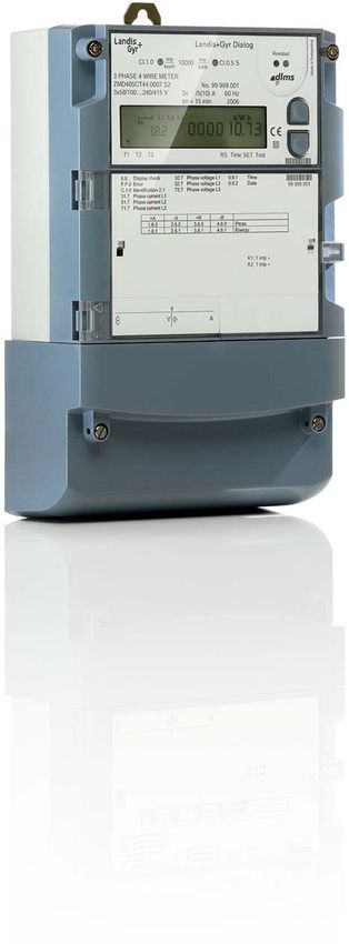
ZMD 410 CT
ZMD405AT/CT, ZFD405AT/CT, ZMD410AT/CT, ZFD410AT/CT
E650 Series 3
E650 Series 3 ZxD400AT/CT – Technical
specifications
General
Voltage
Nominal voltage Un ZMD400xT
3 x 58/100 V to 69/120 V
3 x 110/190 V to 133/230 V Measurement behaviour
3 x 220/380 V to 240/415 V Starting current ZxD405xT
Extended operating voltage range According to IEC 0.1% In
3 x 58/100 to 240/415 V Typical 0.07% In
5||1 A as 1 A meter
Nominal Voltage Un ZFD400xT
3 x 100 to 120 V Starting current ZxD410xT
3 x 220 to 240 V According to IEC 0.2% In
Extended operating voltage range 3 x 100 to 415 V Typical 0.14% In
5||1 A as 1 A meter
Voltage range 80 to 115% The start-up of the meter is controlled by the starting
power and not by the starting current.
Frequency
Nominal frequency fn 50 or 60 Hz Starting power in M-circuit single phase
Tolerance 2% Nominal voltage x starting current
Starting power in F-circuit all phases
IEC-specific data
Nominal voltage x starting current x √3
Current
Nominal current In 1 A, 2 A, 5 A, 5||1 A MID-specific data
Maximal current Imax Current (for classes B and C)
Metrological 2 A, 5 A 200% In Rated current In 1.0 A, 5.0 A
Metrological 1 A 2 A, 10 A
Metrological 5||1 A 6A Minimum current Imin 0.01 A, 0.05 A
Thermal 1 A, 2 A, 5 A, 5||1 A 12 A
Transitional current Itr 0.05 A, 0.25 A
Short-circuit current 0.5 s with 20 x Imax
Maximum current Imax 2.0 A, 10.0 A
Measurement accuracy
ZxD405xT Measurement accuracy to EN 50470-3
Active energy, to IEC 62053-22 class 0.5 S ZxD400xT classes B and C
Reactive energy, to IEC 62053-23 accuracy 1%
Measurement behaviour
ZxD410xT Starting current Ist
Active energy, to IEC 62053-21 class 1 Class B: Ist 0.002 A, 0.01 A
Reactive energy, to IEC 62053-23 accuracy 1% Class C: Ist 0.001 A, 0.005 AZMD 410 CT
General
Operating behaviour
Voltage failure (power-down)
Bridging time 0.5 s
Data storage after another 0.2 s
Switch off after approx. 2.5 s
Voltage restoration (power-up)
Function standby 3 phases after 2 s
Function standby 1 phase after 5 s
Detection of energy direction and phase voltage
after 2 to 3 s
Power consumption Fast transient burst test to IEC 61000-4-4
Power consumption per phase in voltage circuit Current and voltage circuits under load
Phase voltage 58 V 100 V 240 V according to IEC 62053-21/23 4 kV
Active power (typical) 0.4 W 0.5 W 0.7 W Auxiliary circuits > 40 V 2 kV
Apparent power (typical) 0.8 VA 1.0 VA 1.7 VA
Fast transient surge test to IEC 61000-4-5
Power consumption per phase in current circuit Current and voltage circuits 4 kV
Phase current 1A 5 A 10 A Auxiliary circuits > 40 V 1 kV
Active power (typical) 5 mW 0.125 W 0.5 W
Apparent power (typical) 5 mVA 0.125 VA 0.5 VA Insulation strength
Insulation strength 4 kV at 50 Hz during 1 min.
Environmental influences
Temperature range to IEC 62052-11 Impulse voltage 1.2/50 s to IEC 62052-11
Operation –40 °C to +70 °C Current and voltage circuits 8 kV
Storage –40 °C to +85 °C Auxiliary circuits 6 kV
Temperature coefficient Protection class ll to IEC 62052-11
Range –40 °C to +70 °C
Average value (typical) 0.012% per K Calendar clock
at cos=1 (from 0.05 Ib to Imax) 0.02% per K Calendar type Gregorian or Persian (Jalaali)
at cos=0.5 (from 0.1 Ib to Imax) 0.03% per K
Accuracy < 5 ppm
Impermeability to IEC 60529 IP51
Backup time (power reserve) meter
Electromagnetic compatibility With supercapacitor > 20 days
Electrostatic discharges to IEC 61000-4-2 Charging time for max. backup time 300 h
Contact discharge 15 kV With battery (optional) 10 years
Battery type CR-P2
Immunity conducted disturbances 2 to 150 kHz
According to CENELEC TR 50579 Display
Characteristics
Electromagnetic RF fields to IEC 61000-4-3 Type LCD liquid crystal display
80 MHz to 2 GHz 10 and 30 V/m Digit size in value field 8 mm
Number of digits in value field up to 8
Radio interference suppression Digit size in index field 6 mm
according to IEC/CISPR 22 class B Number of digits in index field up to 8ZMD 410 CT
Inputs and outputs
Control inputs
Control voltage US 100 to 240 VAC
Input current < 2 mA ohmic at 230 VAC
Output contacts
Type solid-state relay
Voltage 12 to 240 VAC/DC
Weight and dimensions
Max. current 100 mA
Weight approx. 1.5 kg
Max. switching frequency (pulse length 20 ms) 25 Hz
External dimensions
Optical test outputs active and reactive energy
Width 177 mm
Type red LED
Height (with short terminal cover) 244 mm
Number 2
Height (with standard terminal cover) 281.5 mm
Meter constant selectable
Height (with extended hook) 305.5 mm
Depth 75 mm
Relay contacts on extension board 326x
Type relay
Suspension triangle
Voltage 240 VAC
Height (with extended hook) 230 mm
Max. current 8A
Height (suspension eyelet open) 206 mm
Max. operations with cos ~1 100 000 op.
Height (suspension eyelet covered) 190 mm
Width 150 mm
Control inputs on extension board 326x
Control voltage US 12 to 24 VDC
Terminal cover
Input current < 6 mA ohmic at 24 VDC
Short no free space
Standard (opaque, transparent) 40 mm free space
Communication interface Long (opaque, transparent) 60 mm free space
Optical interface to IEC 62056-21 GSM 60 mm free space
Type serial, asynchronous, half-duplex ZxB type 80 mm 80 mm free space
Max. transmission rate 9600 bps ZxB type 110 mm 110 mm free space
Protocols IEC 62056-21 and dlms ADP2 adapter
Communication units
Material housing
Exchangeable communication units for various
applications. Polycarbonate, partly glass-fibre reinforced
Additional power supply (optional) Environmental
On extension board 045x RoHS compliant design
Nominal voltage range 100 to 240 VAC/DC
Tolerance 80 to 115% Un Connections
Frequency 50 or 60 Hz Phase connections
Max. power consumption 6.8 W Type screw type terminals
Diameter 5.2 mm
On extension board 046x and 326x Recommended conductor cross section 4 to 6 mm2
Nominal voltage range 12 to 24 VDC Screw head Pozidrive Combi No. 2
Tolerance 80 to 115% Un Screw dimensions M4 x 8
Max. power consumption 046x 3.5 W Screw head diameter ≤ 5.8 mm
Max. power consumption 326x 5.5 W Tightening torque < 1.7 Nm
On extension board 047x Other connections
Nominal voltage range 12 to 60 VDC Type screwless spring-type terminal
Tolerance 80 to 115% Un Max. current of voltage outputs 1A
Max. power consumption 5.0 W Max. voltage of inputs 250 VZMD 410 CT
Meter dimensions (standard terminal cover)
6.2 75
extended hook: 230
extended hook: 305.5
standard hook: 206
standard hook: 281.5
190
26
40
150
177 75
Terminal dimensions
12.5
5.2
16 10 10 10 10 10 10 10 10 10
150
168ZMD 410 CT
Terminal layout according to DIN
Control inputs and/or Pulse Communication
output contacts of inputs interfaces
extension board Communication unit
Control inputs
and/or
U1 U2 U3 N output contacts
Voltage outputs
U2 U3
I1 U1 I1 I2 I2 I3 I3
N
Voltage connections
Current connections
Symmetrical terminal layout (optional, ZMD400 only)
Control inputs and/or Pulse Communication
output contacts of inputs interfaces
extension board Communication unit
Control inputs
and/or
U1 U2 U3 N output contacts
Voltage outputs
U2 U3 N
I1 U1 I2 I3 I3 I2 I1
Voltage connections
Current connectionsZMD 410 CT
Type designation ZMD 4 10 C T 44 4207 S3
Network type
ZFD 3-phase 3-wire network (F-circuit)
ZMD 3-phase 4-wire network (M-circuit)
Connection type
4 Transformer operated
Accuracy class
10 Active energy class 1 (IEC), B (MID)
05 Active energy class 0.5s (IEC), C (MID)
Measured quantities
C Active and reactive energy
A Active energy
Construction
T With exchangeable communication units
Tariffication
21 Energy rates, external rate control via control inputs
24 Energy rates, internal rate control via time switch
(additionally possible via control inputs)
41 Energy and demand rates, external rate control via control inputs
44 Energy and demand rates, internal rate control via time switch
(additionally possible via control inputs)
All versions with 3 control inputs and 2 output contacts
Additional functions
000x No extension board
060x 6 outputs
240x 2 control inputs, 4 outputs
420x 4 control inputs, 2 outputs
326x 3 control inputs, 2 relays outputs, auxiliary power supply 12 to 24 VDC
045x 4 outputs, auxiliary power supply 100 to 240 VAC/VDC
046x 4 outputs, auxiliary power supply 12 to 24 VDC
047x 4 outputs, auxiliary power supply 12 to 60 VDC
xxx0 No additional functions
xxx2 DC-magnet detection
xxx7 Load profile
xxx9 DC-magnet detection and load profile (integrated terminal cover switch option only available
in this configuration)
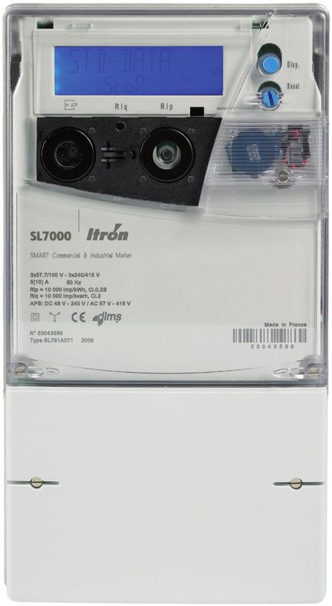
Series 3SL7000
Specifiche Tecniche Dimensioni
Valori Nominali Tensione: 3*57.7/100V sino a 3*277/480V auto 180
Corrente Diretta: ranging In 5A, Imax 120A
Corrente: Ib 1A, Imax 10A
325 mm with standard terminal cover
Tipi di inserzione Inserzione Diretta: 4 fili operabile anche a 3 fili senza
358 mm with extended terminal cover
neutro
Inserzione su TA e TV: 3 o 4fili
Precisione Inserzione Diretta Classe 1 o MID B Classe
Inserzione su Ta e TV: 0.2S, 0.5S o MID C Classe
Energia reattiva: 1 o2
Frequenza 50 / 60 Hz
Standards IIEC 62052, IEC 62053, MID standard EN50470-1 ed EN50470-3 -
CE standards (meccanici, climatici, elettrici, elettromeccanici,
metrologici)
Comunicazione Porta IR (IEC 61107), RS232C e/o RS485 Protocollo DLMS-Cosem
(IEC 62056)
Integrato in gran parte dei principali sistemi SW di lettura (AMR)
Accessori
Comunicazione Modem esterni (es. Kit GSM Telemetering Itron)
Modem Sparklet Itron, alimentati dal contatore, alloggiabili sotto al
201
230
239
251
coprimorsetti
Connessioni per dispositivi esterni
Sonda ottica per lettura porta IR da PC
Setup Tool software per monitoraggio, lettura e configurazione
Itron ACE Pilot Utility Software
150
62
Installazione Etichette per rapporti TA e TV
97
Kit per sigillatura
Documentazione Certificato di test
Manuale d’uso ed 85
installazioneYou can also read