Guidance, Navigation, and Control enabling Retrograde Landing of a First Stage Rocket
←
→
Page content transcription
If your browser does not render page correctly, please read the page content below
Guidance, Navigation, and Control enabling Retrograde Landing
                     of a First Stage Rocket
                           Christian Canham         Meaghan Podlaski          Luigi Vanfretti
                            Department of Electrical, Computer, and Systems Engineering
                                          Rensselaer Polytechnic Institute
                                              Troy, NY, United States
                                      {canhac, podlam, vanfrl}@rpi.edu

Abstract                                                       gines in retrograde long enough to remove its horizontal
                                                               and vertical velocities. This paired with gimbaled engines
A Modelica model of a of a rocket’s first stage is devel-      and control surfaces, such as grid fins, allow the first stage
oped, designed to be representative of the launch vehicles     to be maneuvered back to a predetermined landing pad.
in use in the United States in the late 2010s. The model       The flight controller is responsible for making these en-
uses initial conditions similar to those observed immedi-      gine and control surface control adjustments using input
ately after a second stage separation at 166 km altitude. A    data from an inertial measurement unit (IMU) and GPS
control system is developed enabling the rocket first stage    positional data.
to land back on Earth’s surface at a predetermined landing
pad in a controlled manner. The control system is evalu-
                                                                  Modeling and simulation of the launch vehicle is crit-
ated based on its ability to compensate for altered initial
                                                               ical in the development in the GN&C control system.
conditions, as well as its ability to minimize acceleration
                                                               Hardware-in-the-loop (HIL) test beds are often times cre-
forces and fuel consumption. The flight path of the sim-
                                                               ated to offer a low cost and rapid platform for the design of
ulated first stage rocket is compared to real-life telemetry
                                                               the control system and the calibration of their parameters
data from a first stage rocket landing showing a similar
                                                               before moving onto developmental prototypes.
trajectory.
Keywords: Rocket, Flight controller, GN&C, Retrograde
Landing, Reaction Control Systems                                 The Modelica first stage rocket model and subsequent
                                                               control system in this work represents early phase devel-
1    Introduction                                              opmental activities that might occur when studying the
                                                               feasibility of certain flight maneuvers. In this case, land-
List of Acronyms and Definitions                               ing a rocket back on Earth after launching a payload into
                                                               orbit. Many simplifications and assumptions are made in
Acronyms                                                       the first stage rocket model including the simplification of
GN&C · Guidance, Navigation, and Control                       the rocket solely operating in the X-Z plane. Neverthe-
HIL · Hardware-in-the-Loop                                     less, the control system core principles are fundamental
IMU · Inertial Measurement Unit                                and could be expanded to address these assumptions as
LEO · Low Earth Orbit                                          the model grows in complexity. The key principle is to
NASA · National Aeronautics and Space Administration           develop this control system despite these simplifications
PD · Proportional and Derivative Controller                    made in the model and show the ability to add features
RCS · Reaction Control System                                  over time.
STS · Space Transport System
                                                                  While Modelica models for a variety of aerospace ap-
Motivation                                                     plications have been successfully demonstrated (Wei et al.
Rapid reusable space launch vehicles have long been a          2015; Re 2011; Briese, Klöckner, and Reiner 2017; Milz
pursuit in the United States since it would dramatically in-   et al. 2019; Batteh et al. 2018; Posielek 2018; Hellerer,
crease accessibility to space. This was partially achieved     Bellmann, and Schlegel 2014), to the knowledge of the
with NASA’s Space Transportation System (STS) Space            authors, there are no publicly available models similar to
Shuttle but failed to offer a fully reusable or low cost       the one proposed in this work. The authors’ believe that
method. Rocket re-usability made significant strides when      the growing interest and on-going advancements on rocket
private space launch companies, including SpaceX and           re-usability can benefit from the availability of an open
Blue Origin, demonstrated the ability to recover the first     source model that allows interested parties to exploit the
stage of the rocket by vertically landing it back on Earth’s   advantages offered by object-oriented modeling provided
surface. This is achieved by relighting the rocket’s en-       by Modelica tools.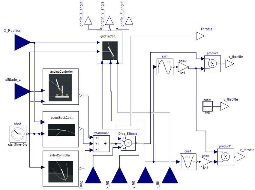
Contribution

This work is relevant to a user of the Modelica language
looking for ways to rapidly develop a control system. In
this case the control system is developed for a first stage
rocket falling back to Earth but similar methods could be
applied to other challenging control problems. The work
shows how a simplified rocket model is nevertheless, an
effective test-bed for the development of a control system
that guides the rocket on a trajectory similar to that used
by actual rockets, such as SpaceX’s Falcon 9. The main
contributions of the paper are the following:

    • Implementation of the control system needed to re-
      cover a first stage rocket by vertically landing at a
      predetermined landing pad.

    • Demonstration of Modelica’s flexibility in creating
      models with increasing complexity leading to mean-
      ingful simulations.                                                   Figure 1. First stage rocket model

    • Documenting an open-source Modelica-based im-            2.1   Mass Properties and Initial Conditions
      plementation of the aforementioned models available      The first stage rocket is modeled with a cylinder with a
      online at: https://github.com/ALSETLab/                  diameter of 3.7m and a length of 48 m. A density of
      RocketLanding                                            0.3g/cm3 was selected based on the Falcon 9 rocket be-
                                                               ing composed of principally aluminum but with a mostly
Paper Organization                                             hollow interior.
                                                                  In this model the frame of reference is the surface of
                                                               the Earth which is simplified with a flat plane. The rocket
The paper is broken down in the following sections: Sec-
                                                               is also assumed to be bounded to the X-Z plane. These
tion 2 describes the first stage rocket model and the sur-
                                                               two simplifications allow for easier control system devel-
rounding environment it operates in. Section 3 describes
                                                               opment in Section 3 and more easily defined initial con-
the control system designed to recover the first stage
                                                               ditions. The initial conditions for the rocket are deter-
rocket by vertically landing at a predetermined landing
                                                               mined from live telemetry data from SpaceX’s own we-
pad. Section 4 compares the simulated Modelica rocket
                                                               bcasts (Pelham 2020). The simulation starts immediately
landing trajectory to real telemetry data from a SpaceX
                                                               after the second stage separation, where the first stage is
Falcon 9 rocket landing. Finally, Section 5 concludes the
                                                               assumed to be in orbit, and therefore, the vertical veloc-
work.
                                                               ity in a flat Earth frame of reference is set to zero. The
                                                               rocket fuselage also starts parallel to the Earth’s surface.
                                                               The initial velocity is purely measured by the horizontal
2     Modelica First Stage Rocket Model                        component of 263 m/s in the X-axis. The altitude is set at
                                                               166km which is representative of the Falcon 9 stage sepa-
                                                               ration for payload deployment in low earth orbit (LEO).
The model developed represents the first stage of a
SpaceX Falcon 9 rocket immediately after second stage          2.2   Engines and Grid Fins
separation. It uses similar mass properties and initial con-   The model includes a single rocket engine with a maxi-
ditions to those observed from publicly available SpaceX       mum thrust of 914 kN. This engine is simplified as a force
telemetry data (Pelham 2020). The model also includes          acting in line with the fuselage of the rocket. The Fal-
the rocket engines and grid fins which are necessary to        con 9 rocket includes nine engines each with a maximum
maneuver the rocket to the landing pad. Lastly the operat-     thrust of 914 kN but only one engine is typically used for
ing environment is taken into account by modeling drag on      landing.
the vehicle as it falls through the Earth’s atmosphere. The       The fuel consumption of the rocket engine is modeled
purpose was to design this model to be as representative       in Figure 2 using fuel tanks and release valves that control
of the actual rocket while making key simplifications that     the injection of liquid kerosene and oxygen into the engine
allow for the implementation of the control system pre-        at a proportion of 2:1 respectively. The same flight con-
sented in Section 3. The complete rocket model is shown        troller output that controls the simulated thrust from the
in Figure 1.                                                   engine is also used to control the fuel injector valves that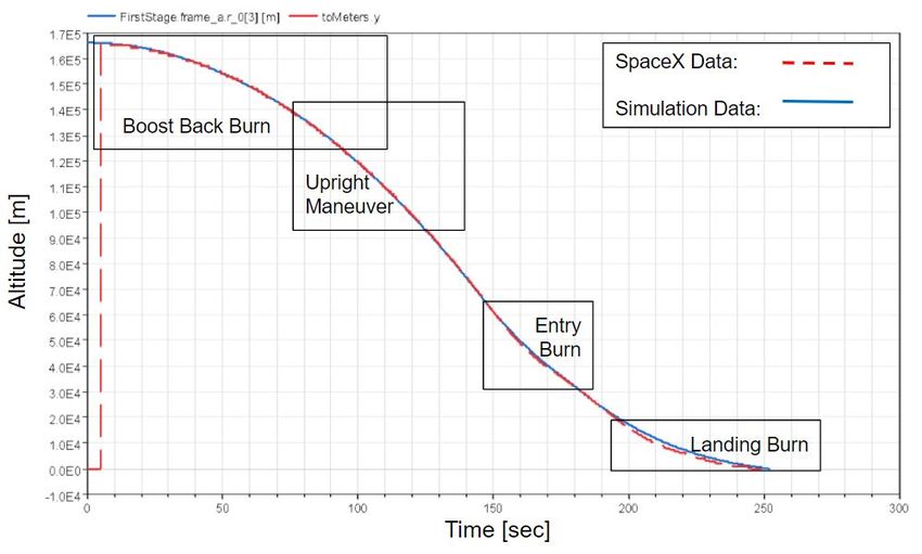
release the fuel into the engine simulated with two tanks use as much fuel with the rocket engines. For these rea-
at ambient pressure. The flow volume through each valve sons it is critical to model the atmospheric drag with ac-
is recorded and can be observed during the rocket simula- curacy.
tion.                                                        The drag of the first stage rocket is modeled with a force
                                                          vector normal to the direction of the rocket’s motion. This
                                                          drag force is calculated using equation 1 where the area A
                                                          is calculated based on the rockets angle relative to the di-
                                                          rection of motion. Velocity V accounts for all vertical and
                                                          horizontal velocity components. The coefficient of drag
                                                          was estimated based on the shape of the cylindrical alu-
                                                          minum fuselage. Selecting this coefficient of drag to be
                                                          constant is a critical simplification. In reality this coef-
                                                          ficient of drag would change based on the wake created
                                                          behind the falling first stage. The air density is calculated
                                                          using equation 2 where h is the altitude above sea level.
                                                          Other variables in equation 2 are held constant and are
                                                          based on the properties of air at sea level.
                                                                                              1
                                                                                       FDrag = CDV 2 Aρ                       (1)
                                                                                              2

                Figure 2. Fuel injector model                                                       gM
                                                                                                 Lh RL
                                                                                      ρ = ρ0 1 −                              (2)
                                                                                                 T0
   The model includes grid fins which impart a torque on
the rocket depending on the grid fin’s rotation angle rela-
tive to the fuselage. This allows the rocket to “steer” itself
to a desired landing zone. On the Falcon 9 rocket these           3    Modelica Flight Controller
grid fins act as a control surface that redirect airflow there-
                                                                  After developing the rocket model, the next step was to
fore they are only effective at lower altitudes where the air
                                                                  create the GN&C flight controller that guides the first
is more dense. In the upper atmosphere Reaction Control
                                                                  stage down to the landing pad. A diagram of the full flight
Systems (RCS) are used to redirect the space vehicle using
                                                                  controller is pictured in Figure 3.
jets of compressed nitrogen. Both these actuators have the
same intended effect so for simplification this model only           The flight controller model is further broken down into
uses the grid fins which are assumed to be equally effec-         four different controllers. The first is the grid fin controller
tive at all altitude.                                             in Section 3.1 which is directly responsible for controlling
   The torque on the rocket is a result of the rotating grid      the angle of each of the three grid fins. The other three
fins depending on the angle of the grid fin relative to the       controller are related to the engine thrust. Each of these
first stage fuselage. Maximum torque is imparted when             three controllers take control of the vehicle at different
the grid fin is at ±45◦ which decreases closer to zero de-        phases of flight but their combined outputs are summed so
grees modeled as a sine function. At zero degrees the grid        if need be they could be working together simultaneously.
fin is perpendicular to the fuselage and no torque is ap-         These three controller include the boost-back controller in
plied.                                                            Section 3.2, the re-entry controller in Section 3.3, and the
   The model includes three grid fins mounted 120◦ apart          landing controller in Section 3.4.
on the circumference of the rocket. Since the rocket is              The flight controller takes as input the altitude and hor-
assumed to operate only in the X-Z plane only one grid            izontal X-axis displacement relative to the landing pad.
fin is used to control the rockets rotation. The other two        On an actual rocket these parameters would be obtained
are simply used to keep the rocket from drifting out of the       though pressure or GPS signals.The flight control also has
X-Z plane due to numerical artifacts in the simulation.           inputs for the angle from all three axes. Normally these
                                                                  would be obtained through an internal IMU internal to the
2.3    Reentry Drag                                               flight controller. The flight controller also has an internal
A space vehicle reentering the Earth’s atmosphere experi-         clock for landing sequences that require a set duration.
ences a considerable amount of drag and successive heat-             As outputs the flight controller has angles for each of
ing as a result of the high speeds acquired during orbital        the three grid fins. The flight controller also has three out-
insertion - this velocity term is squared in the drag equa-       puts for each of the three axes components in the engine
tion. If the reentry trajectory is optimized this inherit drag    thrust. The engine model then uses these thrust compo-
will help slow down the the vehicle reducing the need to          nents to determine the total thrust force vector.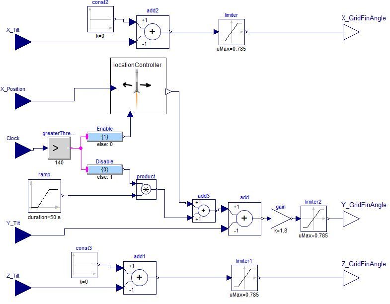
an upright vertical position relative to the Earth’s surface.
                                                                As discussed in Section 2.1 the first stage initially only
                                                                has a horizontal velocity. Once the rocket engines nearly
                                                                remove this horizontal velocity the rocket needs to be ro-
                                                                tated to a vertical position so the engines can begin slow-
                                                                ing down the rocket in the Z-axis. This rotation is accom-
                                                                plished by comparing the rocket’s rotational angle with
                                                                that of a gradual ramp function which initiates at a pre-
                                                                determined altitude. A simple proportional controller rel-
                                                                ative to the changing ramp function is used to bring the
                                                                rocket to the upright position. Even after the ramp func-
                                                                tion has finished bringing the rocket to the vertical position
                                                                it still plays a critical roll in keeping the rocket vertical as
                                                                it comes down for a landing.
                                                                    The second task of the Y-axis grid fin is to guide the
              Figure 3. Flight controller model
                                                                rocket first stage to the landing pad. This is handled by
                                                                the location controller which operates within the grid fin
3.1   Grid Fin Controller                                       controller. This location controller is only enabled after
The grid fin controller in Figure 4 is responsible for de-      the rocket has transitioned to the upright position. The
termining the angle of all three grid fins which impart a       location controller uses proportional and derivative gains
torque on the rocket allowing it to maneuver to the landing     using the horizontal displacement from the landing pad
pad. As mentioned in Section 2.2 the rocket is assumed to       as input. The gains within this PD controller were later
operate only in the X-Z plane. Therefore, only the Y-axis       tweaked upon evaluated the flight trajectory of the rocket.
grid fin is responsible for guiding the rocket to the landing
                                                                3.2    Boost-Back Controller
pad. The other two grid fins are simply present to keep
the first stage rocket from drifting out the X-Z plane. Nu-     The initial 263 m/s horizontal X-axis velocity gained dur-
merical artifacts from the simulation solver have shown         ing orbital insertion needs to be removed in order to land
to result in slight drifting which then compounds until the     the first stage back at the landing pad. This is achieved by
rocket is out of control and tumbling through the atmo-         firing the rocket engines in retrograde where the thrust of
sphere.                                                         the engine is normal to the direction of travel. The rocket
                                                                maintains its horizontal angle during this flight phase with
                                                                the help of the grid fin controller discussed in Section 3.1.
                                                                    As input, the boost-back controller takes the horizon-
                                                                tal displacement relative to the landing pad as well and an
                                                                internal clock. The controller directs the engine to fire at
                                                                time zero and continue until the horizontal velocity falls
                                                                below a certain thresh-hold value of 50 m/s. Some hori-
                                                                zontal velocity is desirable in order to minimize the flight
                                                                path distance taken by the first stage rocket.
                                                                3.3    Reentry Controller
                                                                Space vehicles experience considerable heating during
                                                                reentry into the Earth’s atmosphere. The space shuttle and
                                                                smaller bluff body space capsules use heat shielded tiles to
                                                                protect the spacecraft and the payload inside. A first stage
                                                                rocket reentering the Earth’s atmosphere doesn’t have this
             Figure 4. Grid fin controller model                luxury of a heat shielded exterior since critical external
                                                                components like the engines will be exposed regardless.
   The grid fin model discussed in Section 2.2 applies a        To mitigate this excessive heating a rocket can instead use
maximum torque when rotated to 45 degrees relative to           its own engines to slow down its velocity.
the first stage fuselage length. For this reason the grid fin      The purpose of the reentry controller is to conduct a
controller applies a hard limit at ±π/4 radians for each of     30 second engine burn during the critical phase of flight
the grid fin input angles. Angles in excess of 45◦ decrease     where aerodynamic forces are the greatest. This reentry
the applied torque. As such there is no reason to operate       burn decreases the rocket velocity considerably minimiz-
in those regions.                                               ing excessive heating. During this entry burn the grid
   The Y-axis grid fin is critical in accomplishing two         fin controller discussed in Section 3.1 keeps the rocket
tasks. The first is maneuvering the first stage rocket to       pointed normal to the direction of motion thereby maxi-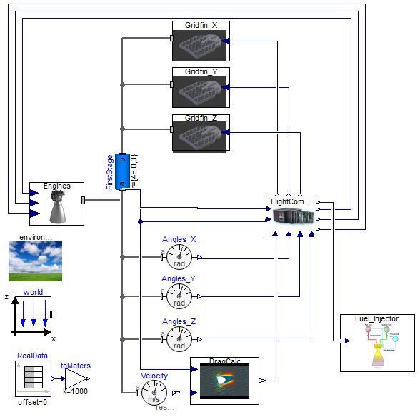
mizing the effectiveness of the entry burn in slowing down
the rocket.
3.4 Landing Controller
The final controller is responsible for landing the rocket
first stage in a controlled manner that minimizes excessive
accelerations. This landing controller takes the altitude
and an internal clock signal as input.
Once the rocket’s altitude falls below the threshold al-
titude of 5 km, a PD controller within the landing con-
troller is enabled which takes over in guiding the rocket
safely down to the landing pad. The gain values in this
PD controller were determined through simulation. Ide-
ally the vertical velocity component of the rocket should
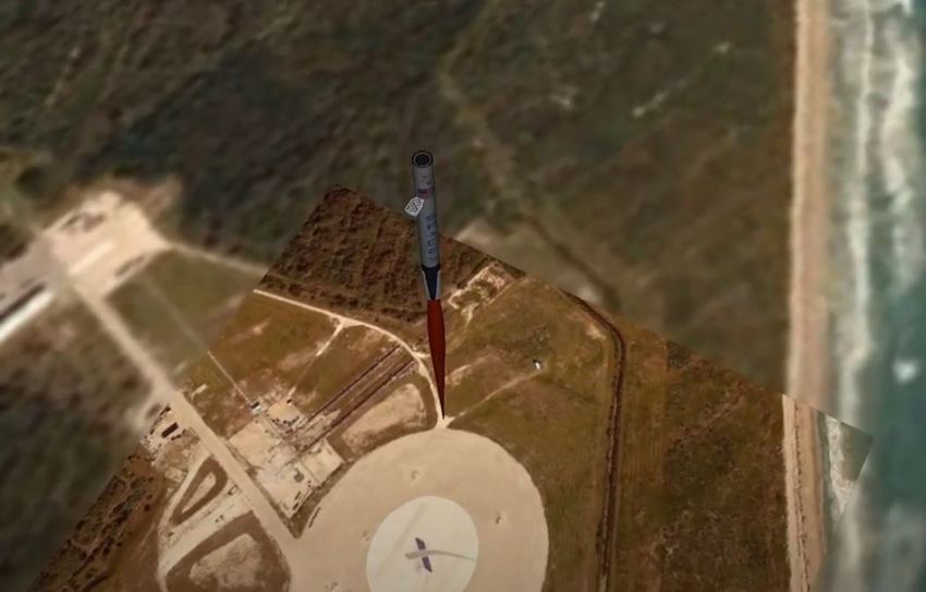
be zero at the moment of touch down. Simultaneously, the
rocket should not undershoot the ground else it would end Figure 5. Flight trajectories
up hovering thereby wasting fuel. A hovering rocket is
also no longer easily maneuverable since the grid fins are Comparison of the two trajectories show near identical
only effective when a velocity component is present. overlap. Overlaid onto the plot are four boxes showing dif-
ferent phases of flight where key maneuvers occur. Each
4 Model Validation of these maneuvers is controlled by one of the controllers
The completed model and early iteration flight controller discussed in Section 3. One subtle difference between the
were simulated with performance evaluated based on the simulation and SpaceX trajectories can be observed in the
rocket’s ability to land in a 50 m diameter landing pad. the landing zone box from 180 - 250 sec. The simulation
These early simulations were critical in the identifica- data shows the first stage rocket slowing down earlier re-
tion of PD controller gain constants used during different sulting in the rocket maintaining a higher altitude. The
phases of flight. Landing controller PD constants were SpaceX Falcon 9 meanwhile appears to wait for a lower
selected such that the touch down velocity was less than altitude before relighting its engines resulting in higher ac-
2 m/s. Meanwhile, grid fin controller PD gains were se- celerations. This lower engine burn is likely attributed to
lected to guide the rocket to the landing pad while mini- the desire to minimize fuel on landings in order to maxi-
mizing overshoot and horizontal oscillations. mize payload carrying capabilities during launch.
With all flight controllers tuned the rocket first stage To better visualize the trajectory of the first stage
was successfully able to land at the predetermined land- rocket, a virtual simulation environment was created us-
ing pad. Figure 5 shows three different flight paths of the ing the DLR Visualization library (Hellerer, Bellmann,
rocket first stage with altitude on the y-axis and horizon- and Schlegel 2014) shown in Figure 7. Using this virtual
tal displacement plotted on the x-axis. Each of the four environment, a user can track the rocket as it maneuvers
curves shown use different initial conditions for the hori- through the different phases of flight including visualiza-
zontal velocity. The curves in green show successful land- tion of grid fin rotation, engine burns, and landing at the
ings where the first stage was able to touch down within pad at Cape Canaveral, FL.
the 50 m diameter predetermined landing pad. The ini- 5 Conclusions
tial condition originally selected for this model was was
293 m/s. The success of these other two trajectories show The rocket model developed in this work and subsequent
the flight controller is robust against initial conditions of flight controller demonstrates the basic control fundamen-
at least ±10 m/s. The curve in red shows an unsuccessful tals in recovering a rocket by landing vertically back on
landing where the rocket undershoot the pad. In this case Earth. In this case, the rocket model was based on the
an initial condition of 240 m/s was not enough horizontal SpaceX Falcon 9 first stage which has proven itself in its
velocity to carry the rocket close to the landing pad be- ability to land in a controlled manner allowing for multi-
fore entering the Earth’s atmosphere where its horizontal ple reuses. Comparing the simulated flight trajectory to
velocity is nearly removed. data from a Falcon 9 landing shows nearly identical flight
This first stage rocket model was designed to be repre- characteristics. While normally these types of simulations
sentative of the SpaceX Falcon 9 in terms of mass proper- would occur in the early development iterations of a con-
ties, initial conditions, and actuator capabilities. A critical trol system rather than recreating one a posteriori, there is
next step was to validate this simulated Falcon 9 rocket value in having a open source Modelica model of a rocket
first stage landing against actual SpaceX telemetry data landing. Even with the primary goal of recovery demon-
(Pelham 2020). Figure 6 shows the simulation trajectory strated in simulation and if real-life, there is likely oppor-
in blue and the SpaceX Falcon 9 telemetry data in red. Al- tunity for optimization of these flight paths with regards to
titude is plotted on the Y-axis with time one the x-axis. minimizing fuel consumption and accelerations.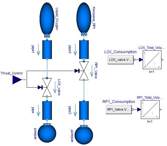
Figure 6. Comparison to Falcon 9 data

                                                                       12th International Modelica Conference, Prague, Czech Re-
                                                                       public, pp. 929–938. DOI: 10.3384/ecp17132929. URL: https:
                                                                       //ep.liu.se/ecp/article.asp?issue=132&article=102&volume=
                                                                       0#.
                                                                    Hellerer, Matthias, Tobias Bellmann, and Florian Schlegel
                                                                       (2014-03). “The DLR Visualization Library — Recent De-
                                                                       velopments and Applications”. In: Proceedings of the 10th
                                                                       International Modelica Conference, Lund, Sweden, pp. 899–
                                                                       911. DOI: 10.3384/ECP14096899. URL: https://ep.liu.se/en/
                                                                       conference-article.aspx?series=ecp&issue=96&Article_No=
                                                                       94.
                                                                    Milz, Daniel et al. (2019-03). “Advances in Flight Dynamics
                                                                       Modeling and Flight Control Design by Using the DLR Flight
                                                                       Visualization and Flight Instruments Libraries”. In: Proceed-
           Figure 7. Visualization of rocket landing                   ings of the 13th International Modelica Conference, Regens-
                                                                       burg, Germany, pp. 481–488. DOI: 10 . 3384 / ecp19157481.
                                                                       URL : https://ep.liu.se/ecp/article.asp?issue=157&article=
Acknowledgements                                                       049&volume=0.
                                                                    Pelham, Jonathan (2020-05). “SpaceXtract”. In: Extraction and
This work was supported in part by the National Aeronautics and        analysis of telemetry from rocket launch webcasts. URL:
Space Administration through the University Leadership Initia-         https://github.com/shahar603/SpaceXtract.
tive Award Number 80NSSC19M0125 for the Center for High-            Posielek, Tobias (2018-11). “A Modelica Library for Space-
Efficiency Electrical Technologies for Aircraft (CHEETA). The          craft Thermal Analysis”. In: Proceedings of the 1st American
second author is supported through the National Science Foun-          Modelica Conference, Cambridge, MA, USA, pp. 46–55. DOI:
dation Graduate Research Fellowship Program under Grant No.            10.3384/ecp1815446. URL: https://ep.liu.se/konferensartikel.
DGE 1744655 and the Chateaubriand Fellowship of the Of-                aspx?series=ecp&issue=154&Article_No=5.
fice for Science & Technology of the Embassy of France in the       Re, Fabrizio (2011). “Modelica Landing Gear Modelling and
United States.                                                         On-Ground Trajectory Tracking with Sliding Mode Control”.
                                                                       In: Advances in Aerospace Guidance, Navigation and Con-
References                                                             trol. Ed. by Florian Holzapfel and Stephan Theil. Berlin, Hei-
Batteh, John et al. (2018-11). “Development and Implementa-            delberg: Springer Berlin Heidelberg, pp. 103–115. ISBN: 978-
   tion of a Flexible Model Architecture for Hybrid-Electric Air-      3-642-19817-5.
   craft”. In: Proceedings of the 1st American Modelica Con-        Wei, Liu et al. (2015-09). “Modeling and Simulation of Liq-
   ference, Cambridge, MA, USA, pp. 37–45. DOI: 10 . 3384 /            uid Propellant Rocket Engine Transient Performance Using
   ecp1815437. URL: https://ep.liu.se/konferensartikel.aspx?           Modelica ”. In: Proceedings of the 11th International Mod-
   series=ecp&issue=154&Article_No=4.                                  elica Conference, Versailles, France, pp. 485–490. DOI: 10.
Briese, Lâle Evrim, Andreas Klöckner, and Matthias Reiner              3384/ecp15118485. URL: https://ep.liu.se/en/conference-
   (2017-05). “The DLR Environment Library for Multi-                  article.aspx?series=118&issue=118&Article_No=52.
   Disciplinary Aerospace Applications”. In: Proceedings of the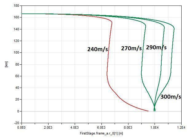
You can also read