How to Interface a Microchip PIC MCU with a hobby R/C Servo
←
→
Page content transcription
If your browser does not render page correctly, please read the page content below
How to Interface a Microchip PIC MCU
       with a hobby R/C Servo
                              Paulo E. Merloti
                               padu@ieee.org
                       Department of Computer Science

        Abstract. Hobby grade servo motors can be used with success in
        several different robotic applications. They have a very simple
        electrical interface and are available in a great assortment of
        specifications and prices. Usually one can get started with a very
        cheap one. This paper will demonstrate how to control one of these
        servos using a PC and a Microchip PIC microcontroller.

1       INTRODUCTION
People are used to do all sorts of stuff using their computers, they write letters,
send e‐mails, play games, and so on. Usually all these activities are bounded
by the virtual world. Everything happens inside the computer, and results are
presented in standard ways, through a screen or in paper through a printer.
People don’t usually expect to control real world objects using the computer,
and still these days, there is an aura of mystery when one sees such
interaction. Unavoidably, interfacing between virtual world and real world
must be accomplished by some peripheral that translates digital information
into motion. An inkjet printer transforms a digital document into a series of
movements of a mechanical arm with two degrees of freedom (including the
angular motion of the cylinder that makes the sheet of paper roll) and controls
rapid release of ink to produce a copy of that digital document on a sheet of
paper. But printing a document is nothing new to us and doesn’t draw uh’s
and oh’s anymore. In the other hand, if you tell your friend that your
computer is the one that controls the lights of your home or turning your AC
on and off, your house will pretty soon be called “the house of the future”.
Transforming digital information into kinesthetic information is mainly
performed by motors. At one time, these motors were pretty hard to control,
expensive and not at everybody’s reach. R/C servos are very attractive because
they are offered in many specifications of angular speed and torque and they
are relatively cheap. Their price can go from anything between $10 and $150
US Dollars. The one I will be using in this paper is a Hitec HS‐325HB.
According to its specs, it is a top ball bearing servo with heavy duty resin
gears and long life potentiometer, which is more than enough for just doing
tests. The manufacturer website [1] presents a list of models offered for a
variety of applications. This model operates at 0.19secs/60° (315.79°/sec) at 4.8

                                        1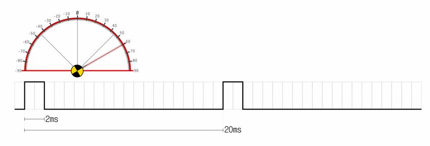
Figure 1: Servo motor used in the examples

Volt and produces an output torque of 3kg.cm. Figure 1 displays a picture of
the servo that I will use throughout this paper.
The algorithms presented in this paper are very simple and are in p‐code, but
the source code is implemented in Mikroelektronika’s Mikropascal, a pascal‐
like compiler that can be obtained from the manufacturer’s web page [2]. They
have a demo version which only restricts the size of the HEX file to 2KB. You
would be amazed at the amount of stuff you can program a MCU to do with
only 2KB. The advantage of using a high level compiler such Mikropascal is
that it is so productive that sometimes you think you are developing regular
windows applications. It provides a series of very useful libraries that really
saves time, but as almost all in life it is a trade off. Developing your code in
assembler may not be as fast as in a high level language, but it could run faster
and in less instructions. For this example, I will be using a PIC 16F877A but
virtually any PIC equipped with a USART port will perform equally well. You
will only need two I/O pins and the USART Rx pin, as well as the usual stuff
(Vcc, GND, OSC, etc).
Finally, the Windows application that sends serial commands to the PIC mcu
was developed using Borland’s Delphi. The executable can be downloaded
from the author’s website [3] and the source code is available by e‐mail request
to the author.

2        ELECTRICAL SPECIFICATION
Servos have a very simple electrical interface; they usually have 3 wires, one
for power, one for ground and the other for the pulse train. Once power
(usually in the 4.8V‐6.0V range) and ground is supplied to the servo, the data
wire is prepared to receive encoded signal in the form of pulse width
modulation (PWM). The duty‐cycle is of 20ms, and the pulse width contained
within those 20ms varies from 1ms to 2ms.

                                             2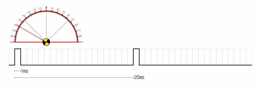
Actually, it is this variation that controls the servo. As a rule of thumb, if a 1ms
pulse is constantly fed to the servo, it will position itself around ‐60° angle,
1.5ms and it will go to the center (0°), and 2 ms will position the servo at +60°
angle. These figures will vary from model to model, but expect them to be
very close to the numbers presented here. Figure 2 shows a diagram of the
signals. Another good source of reference for controlling servos with PIC
microcontrollers is the Images SI Inc. website [4] and also for a series of other
robotics and electronics related projects.

                                             (a)

                                             (b)

                                             (c)

Figure 2: PWM Waveforms: (a) Pulse width of 1ms takes servo head to -60°, (b) Pulse width of
1.5ms takes servo head to 0°, and (c) Pulse width of 2ms takes servo head to +60°.

                                             3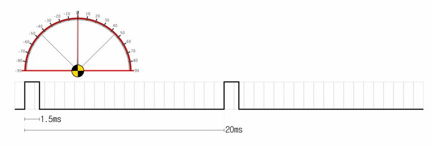
Figure 3: Schematics of the Wiper Servo Controller

2.1 Schematics
Some of the PIC controllers have a dedicated feature that generates PWM
waveforms, but according with existing literature [5] it is not recommended
for this application. The author has not conducted any experiments to validate
these statements. The PWM waveform can also be generated by creating a
delay on the main loop of the PIC application or using interrupts. The choice
of which pin to use to drive the pulse hi and low depends on your application,
in truth, any pin will suffice.
Figure 3 displays the schematics of the required components needed to control
a servo.

3       CONTROLLING THE SERVO
In this section we will show how to write code for the PIC microcontroller that
will cause the servo to turn from one side to another. The algorithm provided
here is shown as a pseudo‐code, but the full source code in Mikropascal can be
found in section 5 Listing 1. This application will be named “wiper” because of
its cyclic left‐right movement that resembles a windshield wiper.

                                             4
Algorithm 1 – The Servo Wiper
   //designed for a PIC16F877A with a 4Mhz clock
   01. interrupt {
   02.   if (TMR0IF flag is raised) {
   03.     flagServo = true;
   04.     TMR0 := 100;
   05.     SetBit(INTCON,TMR0IE);
   06.     ClearBit(INTCON,TMR0IF);
   07.   }
   08. }

   09. main_body {
   10.   TRISC = 0;
   11.   delay = 1000;              //-60
   12.   increment := 1;
   13.   steps := 10;               //10 steps = approx. 1 degree
   14.   OPTION_REG := $86;         //setup TMR0 to trigger
   15.   TMR0   := 100;             //every 20ms
   16.   SetBit(INTCON,GIE);
   17.   SetBit(INTCON,TMR0IE);

   18.     while (1==1) {
   19.       if (flagServo) {
               //generate pulse with width = “delay” microseconds
   20.         SetBit(PORTC,0);
   21.         delay_microseconds(delay);
   22.         ClearBit(PORTC,0);
               //increase/decrease angle
   23.         delay = delay + increment * steps;
   24.         if (delay > 2000) {
   25.           delay = 1999;
   26.           increment = -1;
   27.         } else if (delay < 900) {
   28.           delay = 901;
   29.           increment = 1;
   30.         }
   31.         flagServo = false;
   32.       }
   33.     }
   34. }

Let’s go slower in this first one and analyze what the program is doing,
starting with the initialization code.
   10.     TRISC = 0;

We start by telling the processor that pins on port C are Output. Then we
initialize the variables that will control the direction of the servo.
   11.     delay = 1000;
   12.     increment := 1;
   13.     steps := 10;

“Delay” is the duration of the pulse in microseconds. “Increment” and “Steps”
will control later the direction which servo is currently turning and at which
speed respectively. Now comes the non‐trivial stuff if you are not experienced
in programming timers and interrupts with the PIC. In the next 4 lines we do

                                      5
two things: 1) we define the TMR0 interval and 2) we enable the interrupt
mechanism on the PIC.
14. OPTION_REG := $86;
15. TMR0 := 100;
16. SetBit(INTCON,GIE);
17. SetBit(INTCON,TMR0IE);
Before explaining what lines 14‐17 do, let’s review working with TMR0 on the
PIC. The fundamental register to control general interrupts in the PIC is the
INTCON. In line 16, we enable the GIE bit (bit 7) of the INTCON that enables
general interrupts. We also need to enable the TMR0 interrupt enable flag (line
17). Lines 14 and 15 control the amount of time between TMR0 interrupts and
are be explained below. It is always appropriate to enable a given interrupt
only after all related parameters are set, otherwise an interrupt could be
triggered before the parameters are defined, and that may cause some
unpredicted behavior to your application.
TMR0 is an 8‐bit register that counts from $00 to $FF (0 to 255). One increment
of TMR0 is synchronized with two instructions cycle of the processor, and
when it overflows ($FF + 1) bit 2 of INTCON is raised (TMR0IF) and an
interrupt is triggered. If you do the math, at a modest processor speed of 4
MHz, this count can go pretty fast; actually it is going to be over in exactly
512µs. What’s the solution then? The PIC provides a “prescaler” mechanism
that divides the incoming clock signals and slows down the counting of
TMR01. The prescaler mechanism can be accessed through the OPTION_REG
register pins 2‐0. In order to assign the prescaler to TMR0, the PSA bit (bit 3) of
the OPTION_REG should be cleared. Table 1 presents the available prescaler
rates.
Taking in consideration the fact that TMR0 increment every two instructions
and one instruction is executed every 4 clock ticks (8 for branching
instructions), calculating the values of TMR0 and OPTION_REG:PS2‐PS0 can
PSA:2 PSA:1 PSA:0 Prescaler Delay
0 0 0 1 cycle
0 0 1 2 cycles
0 1 0 4 cycles
0 1 1 8 cycles
1 0 0 16 cycles
1 0 1 32 cycles
1 1 0 64 cycles
1 1 1 128 cycles
Table 1: OPTION_REG register bits and corresponding prescaler delays
1 The prescaler can also be used with the watchdog timer (WDT)
6be done in the following manner:
TMR0 value = 256 – DelayCycles (1)
TMR0 counts from $00 to $FF, it means that if we initialize it with any other
value, it will start counting from that value, thus generating the desired timer
interval. DelayCycles is calculated in the following way:
DelayCycles = DelayInSeconds * FrequencyInSeconds / 8 (2)
We divide by 8 because it is 2 instructions per count * 4 clock ticks per
instruction, totaling 8 clock ticks per TMR0 count. For example, if we want to
initialize TMR0 with 120µs, we would perform the following calculation:
DelayCycles = (120µs)s * (4Mhz)s / 8
= 120 * (10‐6) * 4 * (106) / 8
= 120 * 4 / 8 = 480 / 8 = 60
And according to (1), the TMR0 shall be initialized with 256‐60 = 196.
If DelayCycles exceeds 256, we must divide it by 2 successively until it
becomes a number smaller than 256. The prescaler value is the number of
divisions by 2 we perform in binary form. In the next example, we calculate
the timer value and prescaler value for 20ms, exactly the duty cycle employed
in Algorithm 1.
DelayCycles = (20ms)s * (4Mhz)s / 8
= 20 * (10‐3) * 4 * (106) / 8
= 20 * 4 * (103) / 8 = 80,000 / 8 = 10,000
In order to make this number smaller than 256, we need to divide it by two 6
consecutive times:
10,000÷2 = 5,000÷2 = 2,500÷2 = 1,250÷2 = 625÷2 = 312.5÷2 = 156.25
256 – 156.25 = 99.75 ≈ 100
As you may notice, the division turns into a fraction. In more time sensitive
applications, this fraction must be taken in consideration. One way this can be
done is by including small loops in the interrupt code. For our application, the
servo mechanism is robust enough to accept this type of error; therefore we
round up the TMR0Value to 100. From the calculation above, the prescaler
must slow down the counting at the 1:64 ratio (26). The power 6 is represented
in binary by 110, which should be assigned to bits PS2:PS0 of the
OPTION_REG register. In line 14 of Algorithm 1, we set the OPTION_REG to
$86 (10000110). The 1 in the bit 7 (_RBPU) disables weak pull‐ups on port B. A
more detailed reference on the workings of TMR0 can be found on [6].
As soon as we enable TMR0IE, it starts counting and pretty soon we will
receive an interrupt request. Therefore, prior to analyzing the main body of the
program, let’s take a closer look at the interrupt procedure.
701. interrupt {
02. if (TMR0IF flag is raised) {
03. flagServo = true;
04. TMR0 := 100;
05. SetBit(INTCON,TMR0IE);
06. ClearBit(INTCON,TMR0IF);
07. }
08. }
Line 2 is not fundamental if the only source of interrupt is TMR0, but as we
will see later, if more sources of interrupt are used (i.e.: USART), then we need
to check if the interrupt procedure was really triggered by TMR0 by simply
checking the value of bit INTCON .TMR0IF. Processing should be very limited
within the interrupt procedure; therefore the only thing we are doing here is to
rise a flag (flagServo) signaling that it’s time to send a pulse to the servo. We
also need to reset the value of TMR0 to 100 (as calculated above) and clear the
TMR0IF bit, or else the interrupt will trigger again as soon as we leave the
procedure.
For the main body of the program we have an endless loop that constantly
checks if the flagServo was raised. If it was then it means that 20ms have passed
since the last interrupt and it’s time to send a pulse. In the case of this
application, the servo was connected to PORTC:, and the pulse width is
formed by creating a delay in the main body before clearing the servo pin
again.
//generate pulse with width = “delay” microseconds
20. SetBit(PORTC,0);
21. delay_microseconds(delay);
22. ClearBit(PORTC,0);
To implement the “wiper” behavior, after sending the pulse we increase the
delay by steps (µs) until 2000µs is reached (60°), then we invert the direction of
the increment so the pulse width starts getting smaller until if finds the 1000µs
boundary at ‐60° and then repeats this operation over and over. The servo
speed in this case is controlled by steps, and roughly 10 steps are equal to 1
degree. At last, we must not forget to reset the flagServo variable in order to
make the application wait until the next interrupt.
4 RECEIVING SERIAL COMMANDS
If we want to control the servo using a PC, the Wiper application shown in the
previous section won’t be of much help, we need some way to send
commands to the PIC mcu and consequently to the servo. Luckily, receiving
serial data using a mid‐range PIC is very easy because it has an USART
(Universal Synchronous/Asynchronous Receiver/Transmitter) port
implemented in hardware. In this section we will show how the author
implemented a basic communication protocol using a Delphi program for
Windows 32 and how to implement serial communication using a
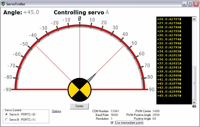
8Figure 4: Screenshot of ServoTroller at 45°
PIC16F877A. Additionally, the author will show a technique on how to control
more than one servo simultaneously.
4.1 The ServoTroller
As said earlier in the paper, the ServoTroller is a Windows 32 compatible
application that presents a graphic interface of the servo head (see figure 4).
Although most servos are designed for the ‐60° to +60°, the ServoTroller
presents a ‐90° to +90° range. On the main screen, the user is allowed to control
the current servo angle by just clicking at a given angle or by dragging the
angle indicator. It is possible to control 2 servos from this application using the
box located at the bottom left corner named “Servo Control”.
Before start using the application, make sure you have the PIC connected to
the PC serial port and that you have the ServoTroller application serial port
properly configured. By clicking the “Options” hyperlink on the main screen,
it is possible to set up among other thins the COM Number and the Baud Rate
that you want to communicate with your PIC mcu. For this experiment the
Baud Rate is set for 9600bps (figure 5).
Also, the standard delays of 1.0ms to 2.0ms for positioning may be inaccurate
for some servos; therefore ServoTroller offers a calibration mechanism in the
Options dialog. The first thing you need to set is where your servo is centered.
Start with 1500µs on the “Pulse Width on center (microseconds)” and increase or
decrease as necessary so your servo head goes to the center position when you
press the “Center” button on the main screen (Angle +00.0). Next step is to
9calibrate the positive side of the servo. Because servos are linear, settings you
make for the positive side are reflected to the negative side. For this example
we are using a Hitec HS‐325HB with a range of ‐60 to +60 degrees, therefore as
shown in figure 5, the Positive Angle Reference (PAR) is set to 60. The Pulse
Width on PAR is the delay in microseconds of the pulse that should move your
servo head to +60° and for the author’s experiment it is set at 2,050µs. You may
need to adjust these numbers until you have your servo correctly calibrated.
Back to the main screen, messages are sent to the PIC when you click at a
given angle on the screen. If Use intermediate points is enabled, then instead of
issuing one single message per click, the software will calculate the difference
between the current and desired angles and issue as many messages per
degree as defined in the Resolution option. Messages are logged in the black list
located at the right side of the window.
Figure 5: ServoTroller options dialog box
A message has the following format:
TCmdRec = packed record
cmd: char;
value: word;
crc: char;
end;
Where cmd defines the recipient servo, in this case ‘A’ or ‘B’; value is a 2 byte
unsigned integer with the pulse width delay in microseconds for that given
angle, and finally the crc character ‘#’. For example, assuming the
configuration set on figure 5 is calibrated against the servo, we would send the
following message to center the servo located on port A (pin PORTC: of the
PIC):
CmdRec.cmd = ‘A’
10CmdRec.value = 1480
CmdRec.crc = ‘#’
This corresponds to the following 4 bytes message:
$65 $C8 $05 $35
The ServoTroller can be downloaded from the author’s website [3] and the
source code in Delphi can be arranged by an e‐mail request to the author.
4.2 Schematics of the Serial Servo Controller
The goal of this paper is not showing how to implement USART
communication on a PIC mcu, therefore we will only present the schematics of
a simple hardware implementation (figure 6) of serial communication between
a PIC and a PC using the RS‐232 protocol, but the implementation details are
out of the scope of this paper.
Figure 6: Schematics of the Serial Servo Controller
114.3 PIC Implementation
Algorithm 2 is very similar to Algorithm 1 except it has the serial data reception
using interrupts. It is presented next in pseudo‐code format and also on Listing
2 in ready‐to‐compile Mikropascal language.
Algorithm 2 – The Serial Multi Servo
//designed for a PIC16F877A with a 4Mhz clock
01. interrupt {
//do we have a timer interrupt?
02. if (TMR0IF flag is raised) {
03. servoA = not servoA
05. flagServo = true;
06. TMR0 := 100;
07. SetBit(INTCON,TMR0IE);
08. ClearBit(INTCON,TMR0IF);
09. }
//or is it a USART interrupt?
10. if (PIR1.RCIF flag is raised) {
11. if (RCSTA.OERR flag is raised) {
//overflow error
12. ClearBit(RCSTA,CREN);
13. SetBit(RCSTA,CREN);
14. exit;
15. }
16. if (RCSTA.FERR flag is raised) {
//stop bit error
17. x := RCREG;
18. } else {
//now we can receive the incoming byte
19. rx = RCREG;
//queuing the received byte into the command array
20. cmd[p_w] = rx;
21. increment(p_w);
22. if (p_w > 3) {
//all four bytes received, flag the main body
//that a new command is ready to be processed
23. rcvd = true;
24. p_w = 0;
25. }
26. }
27. SetBit(PIE1,RCIE);
28. ClearBit(PIR1,RCIF);
29. }
30. }
31. main_body {
//initialization
32. TRISC = 0;
33. servo = 1;
34. rcvd = false;
35. dirA = 1237;
36. dirB = 1237;
37. p_w = 0;
38. OPTION_REG = $85;
39. TMR0 = 100;
40. Initialize_USART(9600);
//interrupt initialization
42. INTCON := 0;
43. PIR1 := 0;
44. PIE1 := 0;
1245. SetBit(PIE1,RCIE);
46. SetBit(INTCON,GIE);
47. SetBit(INTCON,PEIE);
48. SetBit(INTCON,TMR0IE);
//main loop
49. while (1==1) {
//receive USART data
50. if (rcvd = true) {
//validate received command
51. if (((cmd[0]==’A’) or (cmd[0]==’B’)) and (cmd[3]==’#’)){
52. if (cmd[0]==’A’) {
//converting two Little Endian bytes
//into one WORD
53. dirA = cmd[2];
54. dirA = dirA shl 8;
55. dirA = dirA or cmd[1];
56. } else (if cmd[0]==66) {
//converting two Little Endian bytes
//into one WORD
57. dirB = cmd[2];
58. dirB = dirB shl 8;
59. dirB = dirB or cmd[1];
60. }
61. }
62. rcvd = false;
63. }
//generate servo PWM
64. if (flagServo) {
65. if (servoA) {
66. SetBit(PORTC,0);
67. delay_microseconds(dirA);
68. ClearBit(PORTC,0);
69. } else {
70. SetBit(PORTC,1);
71. delay_microseconds(dirB);
72. ClearBit(PORTC,1);
73. }
74. flagServo = false;
75. }
76. }
77. }
As you may have noticed, this algorithm uses the same concept of Algorithm 1
with a few differences. The first one is in the initialization (lines 32‐48) where a
few extra variables were included and USART interrupt was also enabled (line
45). The variable p_w defined in line 37 is a writing pointer used by the USART
interrupt. Because USART receives one byte at time, we need some mechanism
to assembly the serial data into a command string again. Another small
difference in the initialization, but a very important one is the TMR0
initialization. The prescaler now has the value of $85 (1:32 reduction). It means
that instead of 20ms interrupts, now we have 10ms interrupts. The reason for
that is because now we control 2 servos, and for that we divided the 20ms
duty cycle into two timeslots.
In the interrupt procedure, we implemented a mutex that switches the servoA
variable each 10ms. In the main body, when a flagServo event is perceived, a
13pulse is going to be created for either PORTC: or PORTC:, according to
the value set to servoA. This way we ensure that one timeslot is triggered
every 20ms, keeping the compliance to the 50 Hz refresh frequency demanded
by the servo. The interrupt procedure also implements the code for receiving
the command string from the USART port.
On the main body of the application, we check for two flags now, the usual
flagServo that is now triggered every 10ms and the rcvd flag. This flag signals
that a new command arrived through the serial port. We must not forget that
value bytes (cmd[1] and cmd[2]) are arriving in Little Endian format, therefore
we need to perform the shifting and or’ing of these two bytes as shown in lines
53‐55 for servo A and lines 57‐59 for servo B.
The generation of the pulse goes very similar to the one we saw on Algorithm
1, except that now when a timer event occurs, we generate pulse for only one
pin alternately. Note that this technique can be used for more than 2 servos by
creating additional timeslots that add up to 20ms. One needs to be careful with
not over splitting the processor time. If no time between pulses is allotted in
the application for processing of other things, the PWM waveform may lose its
form and erratic behavior may occur.
5 SOURCE CODE
Listing 1 – ServoWiper.ppas
program ServoWiper;
var
dirS: integer;
dirS10: byte;
flagServo: boolean;
increment: short;
steps: short;
procedure interrupt;
begin
//timer section
if TestBit(INTCON,TMR0IF)=1 then
begin
flagServo := true;
TMR0 := 100;
SetBit(INTCON,5); //set TOIE
ClearBit(INTCON,2); //clear TOIF
end;
end;
begin
trisc := 0; // designate portc as output
PORTC := $FF;
delay_ms(1000);
PORTC := $00;
dirS := 910; {-60}
dirS10 := Byte(dirS div 10);
increment := 1;
14//10 steps = approx. 1 degree
steps := 30;
OPTION_REG := $86; // assign prescaler to TMR0
// PSA: 0 (prescaler assigned to TMR0)
// PS2: 1
// PS1: 1
// PS0: 0 (110 = 2^6 = 64)
TMR0 := 100; // interval of 20 miliseconds
SetBit(INTCON,GIE);
SetBit(INTCON,5);
while true do
begin
{generate servo PWM}
if flagServo then
begin
SetBit(PORTC,0);
delay_cyc(dirS10);
ClearBit(PORTC,0);
{increase/decrease angle}
dirS := dirS + increment * steps;
if dirS > 2050 then
begin
dirS := 2049;
increment := -1;
end
else if dirS < 910 then
begin
dirS := 911;
increment := 1;
end;
dirS10 := Byte(dirS div 10);
flagServo := false;
end;
end;
end.
Listing 2 – MultiServo.ppas
program MultiServo;
var
x, rx: byte;
rcvd: boolean;
dirA, dirB: word;
dirA10, dirB10: byte;
cmd: array[4] of byte;
p_w: byte;
servo: byte;
flagServo: boolean;
n: string[20];
procedure interrupt;
begin
//timer section
if TestBit(INTCON,TMR0IF)=1 then
begin
15servo := servo + 1;
if servo > 2 then servo := 1;
flagServo := true;
TMR0 := 100;
SetBit(INTCON,5); //set TOIE
ClearBit(INTCON,2); //clear TOIF
end;
//test USART interrupt
if TestBit(PIR1,RCIF)=1 then
begin
if TestBit(RCSTA,FERR)=1 then
begin
x := RCREG;
end
else begin
rx := RCREG;
cmd[p_w] := rx;
p_w := p_w + 1;
if p_w > 3 then
begin
rcvd := true;
p_w := 0;
end;
end;
SetBit(PIE1,RCIE);
ClearBit(PIR1,RCIF);
end;
end;
procedure Setup;
begin
Usart_init(9600);
USART_Read;
INTCON := 0; // all interrupt bits off
PIR1 := 0;
PIE1 := 0; // disable all ext. interrupts
SetBit(PIE1,RCIE);
SetBit(INTCON,GIE);
SetBit(INTCON,PEIE);
SetBit(INTCON,5);
end;
begin
trisc := 0; // designate portc as output
servo := 1;
cmd := 0;
rcvd := false;
dirA := 1237;
dirB := 1237;
p_w := 0;
OPTION_REG := $85; // assign prescaler to TMR0
// PSA: 0 (prescaler assigned to TMR0)
// PS2: 1
// PS1: 0
// PS0: 1 (100 = 2^5 = 32)
TMR0 := 100; // interval of 10 miliseconds
Setup;
16while true do
begin
//receive USART data
if rcvd = true then
begin
//validate received string
if ((cmd[0] = 65) or (cmd[0] = 66)) and (cmd[3]=35) then
begin
//data is valid
if cmd[0] = 65 then //'A'
begin
dirA := Byte(cmd[2]);
dirA := dirA shl 8;
dirA := dirA or cmd[1];
dirA10 := Byte(dirA div 10);
end
else if cmd[0] = 66 then
begin
dirB := Byte(cmd[2]);
dirB := dirB shl 8;
dirB := dirB or cmd[1];
dirB10 := Byte(dirB div 10);
end;
end;
rcvd := false;
end;
{generate servo PWM}
if flagServo then
begin
case servo of
1: begin
SetBit(PORTC,0);
delay_cyc(dirA10);
ClearBit(PORTC,0);
end;
2: begin
SetBit(PORTC,1);
delay_cyc(dirB10);
ClearBit(PORTC,1);
end;
end;
flagServo := false;
end;
end;
end.
6 CONCLUSION
In this paper we presented a very basic technique on how to interface a PIC
Micro with a servo used in the R/C hobby market. Additionally, it was also
shown how to receive serial data from a PC that controls the direction of the
servo. R/C servos are easily found in hobby shops and depending on your
application they may be very inexpensive. They are especially appropriate for
robotic applications due to internal positioning control and relatively high
torque.
17Experiments performed by the author have shown that by using the approach
demonstrated in the MultiServo application communication between the PC
and the servo is flawless, but if serial messages are sent in rapid succession,
the movement of the servo head starts getting very jittery. Although the
author still doesn’t have a formal explanation for this behavior, he
hypothesizes that it is due to the non real‐time nature of Microsoft Windows
and PC serial ports that are incapable of sending the messages with perfect
timing. An improvement for this model would be changing the content of the
serial message that departs from the PC to discrete angles instead of
microsecond delays. The PC application would instead send a command with
a discrete angle (i.e. +35°) and the PIC would convert this angle into a
microsecond delay by looking at an internal lookup table.
The author wishes to thank the people of the “PicList” discussion group for
the innumerous suggestions and advices they gave on this and lots of other
topics related to the PICMicro and electronics.
REFERENCES
1. Hitec Website. “http://www.hitecrcd.com”. 2005
2. Mikrielektronika Website. “http://www.mikroelektronika.co.yu”, 2005.
3. P. E. Merloti Website, “http://www.merlotti.com/EngHome/Computing/
software.htm”, 2005.
4. Images SI, Inc Website, “http://www.imagesco.com”, 2005.
5. M. Predko, Programming and Customizing PICmicro Microcontrollers. 2nd Ed.,
McGraw-Hill, New York, NY, 2002.
6. PICmicro Mid-Range MCU Family Reference Manual. Microchip Website,
“http://www.microchip.com”, 2005
18You can also read