Imaging Diagnostico e Tecnologie in TC - Pisa, 20/12/2016 Vito Faranna - Ordine Ingegneri Pisa
←
→
Page content transcription
If your browser does not render page correctly, please read the page content below
Imaging Diagnostico
 e Tecnologie in TC

      Pisa, 20/12/2016

       Vito Faranna
2
PUREViSION Optics
From photon generation, beam distribution to efficient detection
X-ray Generation
Small focal spot utilization for a wider variety of
exams
X-ray Beam Distribution
Re-engineered Optics Assay for optimized X-ray
beam spectrum
X-ray Transmission
Adaptive scatter correction ensuring uniform
image quality
X-ray Detection
PUREViSION Detector – high precision
manufacturing process produces a scintilator
with 40% increased light output
3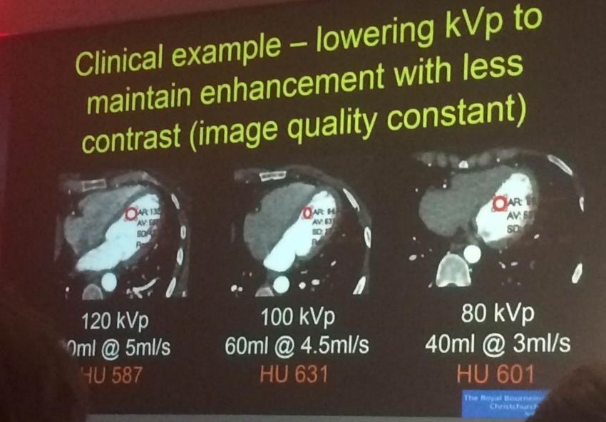
X-Ray Beam Distribution

Optimized X-Ray Beam Spectrum

     Adaptive beam shaping optics ensure homogenous photon spread maximizing image resolution, while minimizing
     dose in a variety of clinical tasks

     Reduction in low energy scattered radiation

                 Old Beam Spectrum                                            New Beam Spectrum

                                                                                                                  4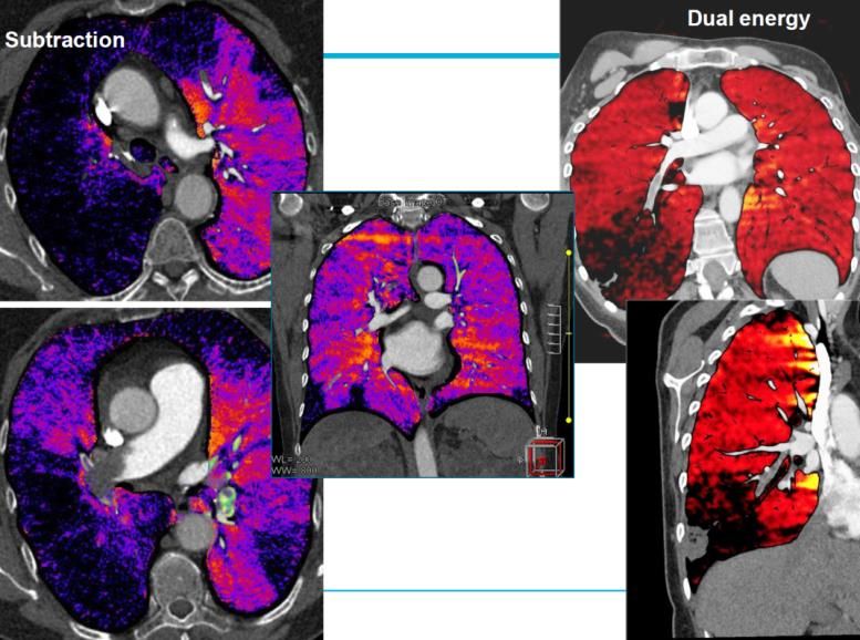
X-Ray Transmission
  +                                     Toshiba   Two ways of managing scatter
                                                   Toshiba
                                                        Adaptive scatter correction utilizing raw data based
                                                        smart modeling ensures uniform image quality
                       Reconstruction

                                          Image
            Sinogram
   -                                                    More primary photons are preserved for
 Photons
                                                        reconstruction = EFFICIENCY

  +                         Competition            Competitors utilize 3D hardware grid
                                                        Primary photon absorption by the grid before
                                                        detection

              Hardware Grid                             Increase in exposure required to maintain signal to
                                                        noise ratio
   -
 Photons

                                                                                                               5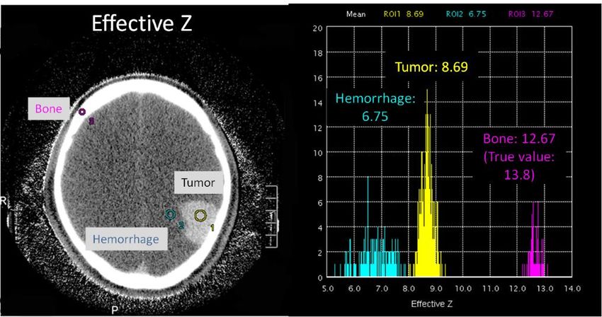
X-Ray Detection
Breakthrough manufacturing techniques
  PUREViSION  detector - 40% increased light
  output resulting in higher detector efficiency

  Micro-blade cutting of a single ceramic ingot
  reduces imperfections ensuring superior
  luminescent properties

                                                   6
Physics
                  400,00

          NOISE   300,00

                  200,00
                                                                               PUREViSION
                                                                               Conventional
                                                    Dose saving by 40%
                  100,00

                    0,00
                           0   50   100       150        200     250     300
                                          TUBE CURRENT

                                                                                              7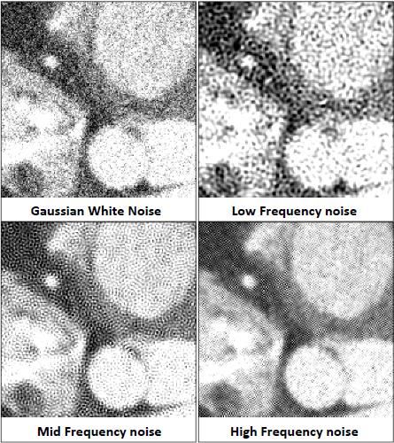
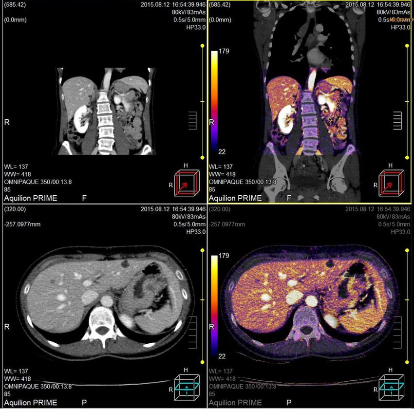
Clinics (risparmio di MDC)

At 80 kVp there are many 30-35 keV photons which are absorbed
     very strongly by iodinated contrast (k-edge = 33.2 keV)
                                                                8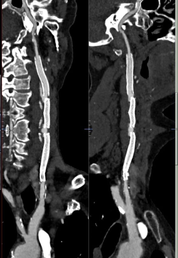
9
Note:

» Per lo stesso valore di SD, è possibile
  modificare il comportamento del «NPS»

» Visivamente l’uomo è sensibile alla
  composizione spettrale del rumore
FIRST (MBIR)
Forward Projected Model-Based Iterative Reconstruction SoluTion

 Scan Acquisition   Original Projection                                Seed
                                                                      Image

                                                            Forward                Optimized
                                                            Projection
                                                            with every iteration
                                                                                               FIRST image
                                                                    Updated
                                                                    Image

                                          Model Based Iterative Reconstruction:
                                           • Integrated and easy to use
                                           • Automated
                                           • Fast

                                                                                                             11
FIRST (Forward projected model-based Iterative Reconstruction SoluTion)
Comparison Engine
Statistical model
Scanner model
Optics model
Cone beam
model
Anatomical based
noise regularizationFIRST (Forward projected model-based Iterative Reconstruction SoluTion)
1. No more kernel but different algorithms
» Body and Cardiac for soft tissues
» Bone for high contrast structures
» Lung
» Brain
2. Works for both Volume and Helical acquisition
3. Integrated into SUREExposure ensuring automatic dose reduction
4. Parallel reconstruction (AIDR 3D & FIRST) with fast
reconstruction time (±3 min/vol)Image quality improvement
FIRST results in:
» Improved SNR at low dose
» Improved Spatial Resolution
SD Spatial Resolution
FBP
AIDR3D
FIRST
0.5% 1%
mAs mAs
0.3%
Low Contrast Phantom FBP vs FIRST (50mAs)83 y.o. man, 80kg, BMI=28.7. Anticoagulant-related subcapsular liver hematoma
FBP AIDR 3D FIRST
DLP = 214 mGy.cm, 3.2 mSv
DLP = 75 mGy.cm, 1.1 mSv
Courtesy of Prof. Blum, Nancy University Hospital, France.Carotid artery stenting
FBP FIRST
120kV / AEC50-250mAs /527.1 mGy.cm/3.1mSv
Courtesy of Prof. Awai. Hiroshima university hospital, Japan.Follow-up after fixation of a OCD fragment in a 16 y.o. man
FC30 – AIDR 3D FIRST Bone
Courtesy of Prof. Blum, Nancy University Hospital, France.Ultra-low-dose CT of the thorax
Literature suggests that
» 0.16 mSv are sufficient to detect > 3 mm nodules
» > 0.30 mSv are necessary to detect emphysema, ground-glass
opacity nodules, nodules less than 3 mm
120kV, 3mAs, FIRST DLP = 13.5 mGy.cm, 0.19 mSv
Courtesy of Prof. Blum, Nancy University Hospital, France.Sub-micro Sv CT for MSK
DLP = 15.9 mGy.cm, 3.5 μSv DLP = 0.6 mGy.cm, 0.13 μSv
Courtesy of Prof. Blum, Nancy University Hospital, France.20
A bit of Subtraction history
‘CT angiography with digital subtraction of extra- and
intracranial vessels’ - Gorzer et al; 1994
1st subtraction technique
N=26
Bone removal 100% success rate
Conclusion: Subtraction allows robust and fast selective
elimination of bony structures and a better analysis of arteries
at the level of the skull base. This is useful of both detection
and therapy planning of intracranial aneurysms
21Subtraction advantages
CTA = ‘golden standard’ for vascular occlusive disease
Problems:
Extensive calcium, stents
blooming artefacts
Overestimation of stenosis
False positive diagnosis of occlusion
22Subtraction advantages
Original image Subtracted image
Original image Subtracted image
23Subtraction advantages
Standard bone removal
24Subtraction advantages
Standard bone removal
25Body Perfusion
Deformable Registration
Registrazione deformabile calcola le differenze tra ogni singola immagine clinica e
compensa il cambiamento di forma e di spostamento della posizione dovuti al movimento
anatomico durante il processo di scansione.
26Subtraction CTA Rigid or non-rigid registration? 26-y-o female with calcified chondroma para-vertebral CT-Perfusion Rigid Registration Non-Rigid Registration
Subtraction advantages
      Willis                Carotid          Endoleak     Small     Coronary subtraction   Run off
                                                         arteries

                                                                      PE Lung
                                          Iodine maps
                                           Abdominal
  Oncology                                  oncology
                   Stents
    MSK

                 Metal                Lipiodol removal
                Artefact                    HCC
               Reduction

                                                                                                     28
Subtraction advantages
DSA-like Subtraction
Removal calcifications & blooming
Removal streak artefacts from stents, clips
Better visualization of lumen
Increased reader confidence
Zero click post-processing
29Subtraction CTA Courtesy University Hospital of Strasbourg, Pr. Roy Case 2: 60-y-o patient 3 stents
Subtraction CTA Courtesy University Hospital of Strasbourg, Pr. Roy Does subtraction help us in this very difficult case?
Subtraction CTA Courtesy University Hospital of Strasbourg, Pr. Roy Does subtraction help us in this very difficult case?
Subtraction CTA Courtesy University Hospital of Strasbourg, Pr. Roy Increased reader confidence Confirms re-stenosis right ICA Stenosis measurement more accurate
Subtraction CTA Courtesy University Hospital of Nancy, Pr. Blum
Case 3: 80-y-o. Surgery in 2019 for giant cell tumor.
Recurrance 2012. Radiotherapy. Follow-up
MRI IDEAL (Dixon)
Fat suppression
sequenceSubtraction CTA Courtesy University Hospital of Nancy, Pr. Blum
Std CT DSA Bone OrthoSubtraction CTA Courtesy University Hospital of Strasbourg, Pr. Roy Case 4: 71-y-o female. Stent in left renal artery
Subtraction CTA Courtesy University Hospital of Strasbourg, Pr. Roy
Bone removal Subtraction
Case 8:
More small peripheral arteries
Improves contrast resolution
Confirmation no distal stenosisLAD Calcification
Pre Contrast Post Contrast
Courtesy Dr K Kofoed, Rigshospitalet, DenmarkLAD Calcification
No hemodynamically significant stenosis is seen.
CTA Subtracted
Courtesy Dr K Kofoed, Rigshospitalet, DenmarkLAD Calcification
No hemodynamically significant stenosis is seen.
Courtesy Dr K Kofoed, Rigshospitalet, DenmarkIn stent Re-stenosis
In stent re-stenosis is seen in the LAD.
Post Contrast Subtracted
Courtesy Dr M Chen, NHLBI, National Institutes of Health, USAIn stent Re-stenosis
In stent re-stenosis is seen in the LAD.
Subtracted
Courtesy Dr M Chen, NHLBI, National Institutes of Health, USAValidation
Subtraction Coronary CT Angiography for the Evaluation of Severely Calcified Lesions Using
a 320-Detector Row Scanner, Yoshioka K & Tanaka R, Current Cardiovascular Imaging
Reports, 2011; 4(6):437-446
Subtraction Coronary CT Angiography for Calcified Lesions, Yoshioka K, Tanaka R, Muranaka
K.Y, Cardiol Clinics, 2012; 30(1):93-102
Improved evaluation of calcified segments on coronary CT angiography: a feasibility study
of coronary calcium subtraction, Tanaka R, Yoshioka K, Muranaka K, Chiba T, Ueda T, Sasaki
T, Fusazaki T, Ehara S, International Journal of Cardiovascular Imaging, 2013, Epub.
Accurate Registration of Coronary Arteries for Volumetric CT Digital Subtraction
Angiography, M. Razeto, J. Matthews, S. Masood, J. Steel, K. Arakita, Proc. SPIE Vol. 8768,
2013.Subtraction CTA
Case 10:
Iodine map differentation
between tumor and cyst
44Dual Energy
Exploits different kV-dependence
700
HU / mg/ml iodine
700
80
600
600
100
80 kVp 40 HU
120
140
500
Enhancement (HU)
500
100 kVp 31 HU
140 Sn
400
120 kVp 26 HU
CT value (HU)
400
300
300
90 HU 140 kVp 22 HU
200
200 140 kVp+Sn 14 HU
100
100 Dual energy subtraction
0
00 5 10 15 mg/ml iodine
0
5 10 15
mg / ml iodineSubtraction Imaging
Exploits total iodine signal
700
HU / mg/ml iodine
700
80
600
600
100
80 kVp 40 HU
120
140
500
Enhancement (HU)
500
100 kVp 31 HU
140 Sn
400
120 kVp 26 HU
CT value (HU)
400
300
300
310 HU 140 kVp 22 HU
200
200 140 kVp+Sn 14 HU
100
100 Subtraction imaging
0 3.4 x higher signal !
00 5 10 15 mg/ml iodine
0
5 10 15
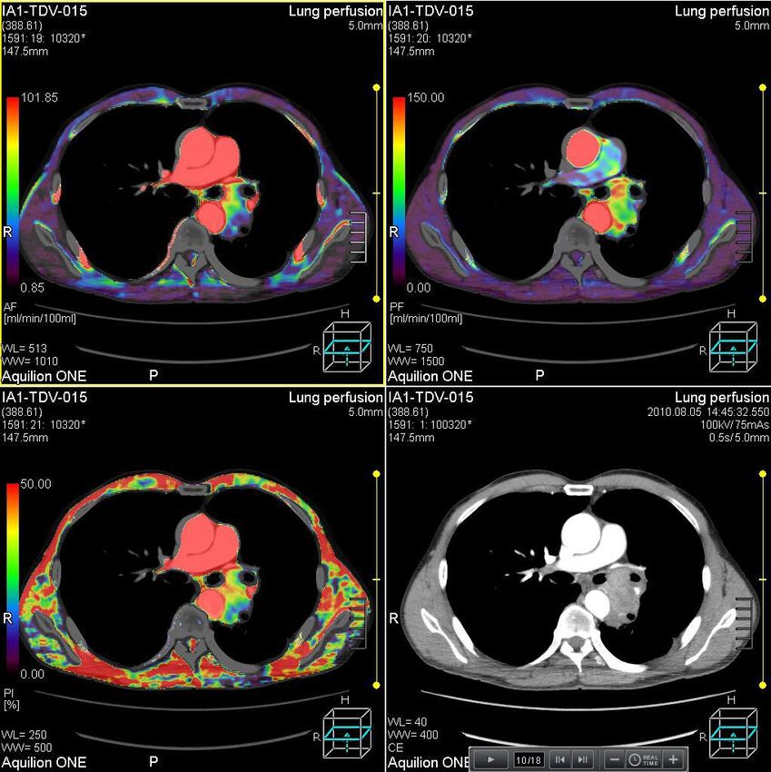
mg / ml iodineClinical benefits:
“This subtraction technique allows for excellent evaluation
of lung parenchyma and pulmonary vessels and achieves a
more than 3 times higher contrast-to-noise ratio than dual
energy images at identical dose.”
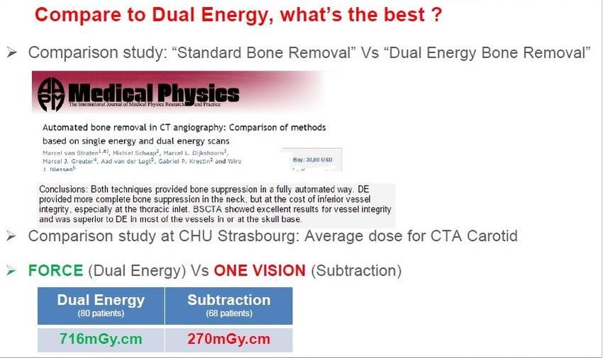
47Subtraction CTA or DE
Subtraction CTA or DE
50
Dual Energy Dual Energy subtracts high energy data from low energy data So, DE is a kind of subtraction........
Dual Energy
     Kidney stone    Virtual Non Contrast           Gout        Iodine Map

                    Blending                               Lung Nodules
    hemorrhage

                                            BHC

       Endoleaks                             Best CNR              MSK

                      Effective Z/
                    Electron density
Dual Energy
Case 11: DE follow-up treatment Nexavar* for HCC
Single energy 6
months post Iodine map
treatment
Blending VNC
* Decreases tumor growth; anti-angiogenesisDual Energy
Case 12: 71-y-o male. Pre-treatment evaluation mass in
paranasal sinus
Iodine map VNC Blending – 110 Equiv. kVVirtual Non Contrast
Source: “Dual Energy Raw Data Based Decomposition Analysis on Aquilion ONE”,
F. Tatsugami et al.Toshiba’s Raw data analysis
» One tube and one detector
» High energy (kVp) during one rotation followed by low energy during another
rotation
Scanned Raw Images
Raw data Water Content ratio
Data Water Content ratio
Projection processing
135 kV
Linear combination
Reconstruction
80 kV
Raw data Images
Bone Content ratio Bone Content ratio» One tube and one detector » High energy (kVp) during one rotation followed by low energy during another rotation Source: Fuminari et al, DE analysis at 320-detector CT (2014)
Publication
1. Chaytor R.J. et al, “Determining the composition of urinary tract calculi using stone-targeted dual-energy CT: evaluation of a low-dose
   scanning protocol in a clinical environment”, Br J Radiology, (2016)

2. Fuchs M. et al, “Acute vertebral fracture after spinal fusion: a case report illustrating the added value of single-source dual- energy CT to
   MRI in a patient with spinal instrumentation”, Skeletal Radiology, (2016)

3. Kiefer T. et al, “Single source dual-energy CT in the diagnosis of gout: Diagnostic reliability in comparison to digital radiography and
   conventional computed tomography of the feet”, Eur J of Radiology 85 (2016)

4. Funabashi N. et al, “Influence of tube voltage and heart rate on Agatson Ca score, novel ECG-gated dual energy reconstruction 320 slice
   CT technique”, Int. J. of Cardiology, Vol. 180, (2015)

5. Diekhoff T. et al, “First experience with single-source dual-energy computed tomography in six patients with acute arthralgia : a
   feasibility experiment using joint aspiration as a reference”, Skeletal Radiology, (2015)

6. Fuminari T. et al, “Measurement of Electron Density & Effective Atomic Number by Dual-Energy Scan Using a 320-Detector CT Scanner
   with Raw Data-Based Analysis: A Phantom Study”, J of comp assisted tomography, (2014)

7. Cai X. et al, “Impact of reduced-radiation dual-energy protocols using 320-detector row computed tomography for analyzing urinary
   calculus components: initial in vitro evaluation”, Urology, Vol. 84, (2014)

8. Diekhoff T. et al, “Detection and Characterization of Crystal Suspensions Using Single-Source Dual Energy Computed Tomography: A
   Model of Crystal Arthropathies”, Investigative Radiology, (2014)

9. Tatsugami F. et al, “Dual energy raw data based decomposition analysis on Aquilion ONE”, VISIONS 23, (2014)
10. Buckley O. et al, “Dual energy CT in the Prime time”, VISIONS 23, (2014)
11. Rogalla P. et al, “One Man’s Trash is Another Man’s Treasure: Dual-energy in Bowel Ischemia”, ISCT (2015)
60
TOSHIBA Super High resolution CT

                      Note:

                      With super high resolution CT, MTF @10% is approx 4x
                      as high as current system (see Figure left).

                      This can be seen in evaluation of lp/cm images (see
                      Figure above).
                                                                             61
TOSHIBA Super High resolution CT
Note:
Clinical images show the difference between conventional CT and super high resolution CT @ D-FOV of 20mm.
The latter (right image) shows much more details and clinical values compared to the former (left image).
6263
64
Il numero degli strati rappresenta il parametro di riferimento per la
suddivisione in classi merceologiche/economiche
Si parla di «Riduzione della Dose»
Si elencano una serie di programmi applicativi che devono essere inseriti
Ma si valutano sempre gli stessi parametri !Classificazione Nazionale Dispositivi
Z11030601 TOMOGRAFI ASSIALI COMPUTERIZZATI - INFERIORE O UGUALE A 2 STRATI
Z11030602 TOMOGRAFI ASSIALI COMPUTERIZZATI - SUPERIORE A 2 STRATI ED INFERIORE A 16 STRATI
Z11030603 TOMOGRAFI ASSIALI COMPUTERIZZATI - SUPERIORE O UGUALE A 16 STRATI ED INFERIORE A 64 STRATI
Z11030605 TOMOGRAFI ASSIALI COMPUTERIZZATI - SUPERIORE O UGUALE A 64 STRATI ED INFERIORE A 128 STRATI
Z11030606 TOMOGRAFI ASSIALI COMPUTERIZZATI - SUPERIORE O UGUALE A 128 STRATI ED INFERIORE A 256 STRATI
Z11030607 TOMOGRAFI ASSIALI COMPUTERIZZATI - SUPERIORE O UGUALE A 256 STRATI
Z11030680 TOMOGRAFI ASSIALI COMPUTERIZZATI (TAC, TC) - COMPONENTI ACCESSORI HARDWARE
Z11030682 TOMOGRAFI ASSIALI COMPUTERIZZATI (TAC, TC) - COMPONENTI ACCESSORI SOFTWARE
Z11030685 TOMOGRAFI ASSIALI COMPUTERIZZATI (TAC, TC) - MATERIALI SPECIFICI
Z11030699 TOMOGRAFI ASSIALI COMPUTERIZZATI (TAC, TC) NON ALTRIMENTI CLASSIFICATI
66Comparazione tra TC a 80 e 160 strati
80 strati 160 strati
Numero di file detettori asse Z 80 80
Numero detettori/fila 896 896
Spessore minimo dello strato 0,5 mm 0, 5 mm
Larghezza detettore asse Z 40 mm 40 mm
Volume acquisito in 10 sec. Pitch 1 1142,8 mm 1142,8 mm
Risoluzione longitudinale in spirale 0,31 mm 0,31 mm
Risoluzione longitudinale in assiale
0,35 mm 0,31 mm
(volume)
67La contestualizzazione dei numeri
Risoluzione di contrasto 4 mm @ 0,3% kV 120 mAs 250 Dose mGy 27 kW 30 Concorrente X 305%
Risoluzione di contrasto 4 mm @ 0,3% kV 120 mAs 82 Dose mGy 8,4 kW 9,84 Toshiba (Prime)
Risoluzione di contrasto 2 mm @ 0,32% kV 120 mAs 353 Dose mGy 31,1 kW 42,36 Concorrente X 186%
Risoluzione di contrasto 2 mm @ 0,3% kV 120 mAs 190 Dose mGy 18,6 kW 22,8 Toshiba (Prime)
Risoluzione di contrasto 4 mm @ 0,3% kV 120 mAs 250 max mA a 0,3 sec. 833,33 mA 100 kW Concorrente X
Risoluzione di contrasto 4 mm @ 0,3% kV 120 mAs 82 max mA a 0,3 sec. 273,33 mA 33 kW Toshiba (Prime)
Risoluzione di contrasto 2 mm @ 0,32% kV 120 mAs 353 max mA a 0,3 sec. 1176,66 mA 142 kW Concorrente X
Risoluzione di contrasto 2 mm @ 0,3% kV 120 mAs 190 max mA a 0,3 sec. 633,33 mA 76 kW Toshiba (Prime)
68You can also read