INDIGO HI-LO INSTRUCTIONS FOR USE 06/21
←
→
Page content transcription
If your browser does not render page correctly, please read the page content below
06/21

        INDIGO HI-LO
        INSTRUCTIONS FOR USE

                          i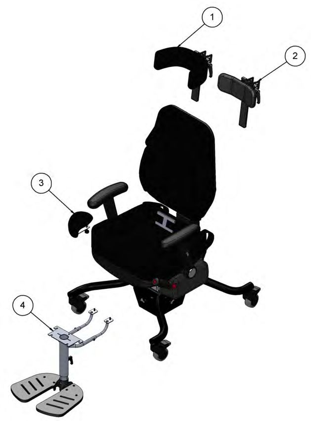
CONTENTS
1.0 Introduction ........................................................................................................... 1
2.0 Illustration of Your Indigo HiLo Seating System ....................................................... 2
  2.1 Technical Data ............................................................................................................. 2
3.0 For your Safety ....................................................................................................... 3
4.0 Unpacking your Indigo HiLo Seating System ............................................................ 4
5.0 Setting up and Adjusting your Indigo HiLo Seating System ...................................... 5
  5.1 Seat Adjustments ........................................................................................................ 5
  5.2 Backrest Adjustments ................................................................................................. 7
  5.3 Armrests ...................................................................................................................... 9
  5.4 Braking System .......................................................................................................... 10
  5.5 Pelvic Lap Strap ......................................................................................................... 12
6.0 Optional Accessories – Fitment and Adjustment ................................................... 13
  6.1 Headrests .................................................................................................................. 14
  6.2 Flip-up Footrest ......................................................................................................... 16
  6.3 Pommel ..................................................................................................................... 17
7.0 Care and Maintenance ......................................................................................... 18
  7.1 Charging the battery ................................................................................................. 18
  7.2 Daily Checks............................................................................................................... 19
  7.3 Annual Service ........................................................................................................... 19
  7.4 Nominal Service Life .................................................................................................. 19
  7.5 Extending Nominal Service Life ................................................................................. 20
  7.6 Documentation/Records ........................................................................................... 21
  7.7 Product Configuration ............................................................................................... 21
8.0 Warranty & Service .............................................................................................. 22
9.0 Continuous Improvement ..................................................................................... 22
10.0 Warranty & Aftersale ........................................................................................... 23
  10.1 Product Information .................................................................................................. 23
  10.2 Service & Inspection Record Form ............................................................................ 23

                                                                                                                                     ii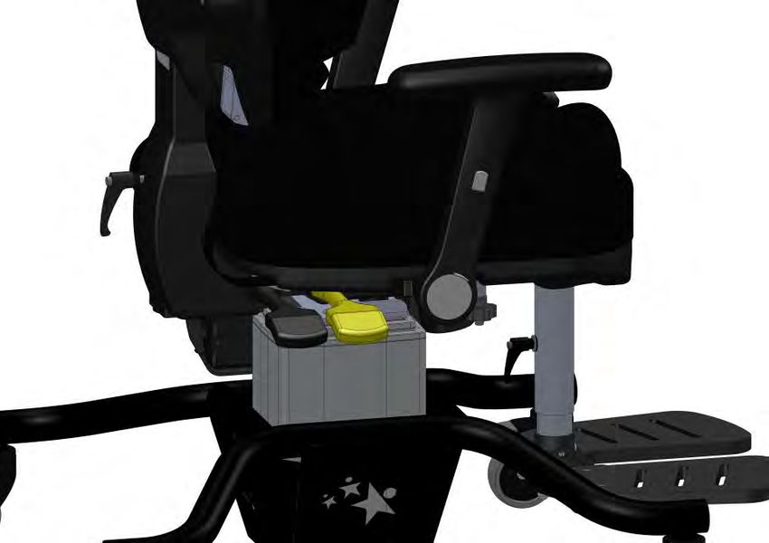
1.0 INTRODUCTION
Thank you for choosing the Indigo HiLo seating system from Smirthwaite.
The IndiGO seating system has been designed for use by teenagers who have mild to
moderate postural management needs. It has been styled to enhance inclusivity into
modern environments, and is particularly suitable for use by children who attend
mainstream school on a periodic basis.
The IndiGO provides a range of features as standard including adjustable back height and
recline angle as well as seat height, depth and tilt angle. The chair includes height adjustable
armrests which can be quickly rotated rearwards to provide easy side transfer in and out of
the chair.
Postural management can be specifically customized to suit a client’s needs by adjusting the
integrated lumbar prompt and thoracic supports.
When ordered, the product can be configured with a high back or low back option.
A range of accessories are available including a pommel, pelvic lap strap, 4-point harness,
flat headrest (height, depth and angle adjustable), a ‘Multi-grip’ headrest (height, depth,
angle and profile adjustable), and a height adjustable footrest with flip-up foot plates.
Smirthwaite can also provide a range of sandals if required.
The IndiGO electric HiLo base includes a user operated brake mechanism and control pad to
provide additional independence and positional security for clients.

           IMPORTANT!
           These instructions should be read by all therapists and carers using the
           equipment and should be retained for future reference. The product should
           always be used under adult supervision.
           A clinical assessment of the child’s needs should be undertaken to ensure the
           Samba chair is correctly adjusted. Adjustments should only be made by a
           therapist, Smirthwaite Technical Product Advisor or suitably trained personnel.
           Any incorrect use of the product and failure to follow the instructions may put
           the user at risk or impede the function. If you have any queries using this
           product or wish for further copies, please do not hesitate to contact our
           Customer Service Team on T: +44 (0)1626 835552.
           This product has been designed and manufactured specifically and solely for use
           by clients with special needs.

                                                                                              1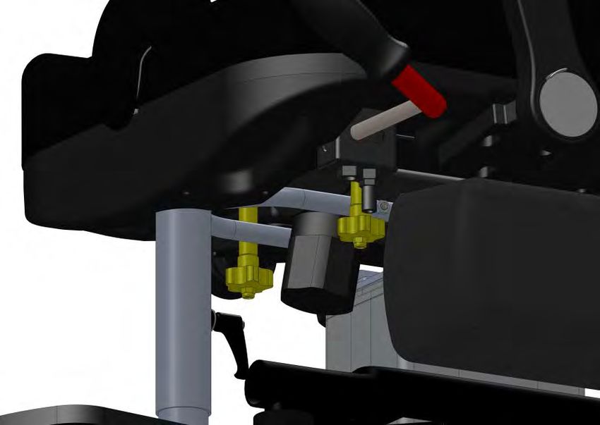
2.0 ILLUSTRATION OF YOUR INDIGO HILO SEATING SYSTEM

      1.   Electric HiLo Chassis
      2.   Seat Capsule
      3.   Backrest
      4.   Armrests
      5.   Footrest
      6.   Battery Pack
      7.   Pommel
      8.   Lap Strap
      9.   User operated brakes

2.1        TECHNICAL DATA
Measurement                                   Size 4      Size 5      Size 6
Seat Height – Floor to seat top (mm)        510 - 760   510 – 760   510 – 760
Seat Depth (mm)                             340 - 420   390 – 470   440 – 520
Seat Width (mm)                                440         490         490
Seat Angle – Prone to supine (°)             3 – 10       3 – 10      3 – 10
Back Angle – Prone to supine (°)              0 - 15      0 – 15      0 – 15
Low back height (mm)                        420 - 500   420 – 500   420 – 500
Low back height (mm)                        560 - 640   560 – 640   560 – 640
Headrest height from top of backrest (mm)   100 - 200   100 – 200   100 – 200
Armrest height (mm)                         190 - 250   190 - 250   190 - 250
Seat to footrest (mm)                       340 - 490   340 - 490   340 - 490
Footprint width x length (mm)               615 x 700   615 x 700   615 x 700
Max user weight (kg)                           125         150         150
Product weight (kg)                             43          44          44

                                                                            2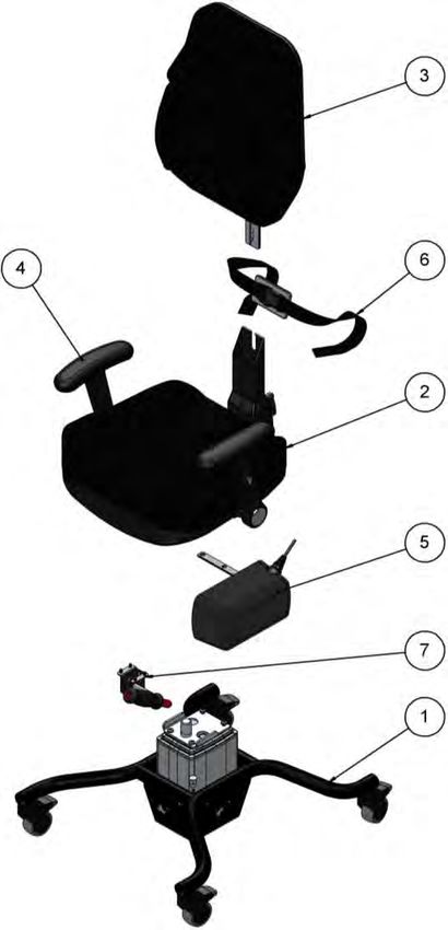
3.0 FOR YOUR SAFETY
STOP!
Please read these instructions CAREFULLY and THOROUGHLY.
Always lock the castors when attaching items, or making adjustments.
There are two methods to lock the brakes on the Indigo HiLo chair:
1) Push the brake lever downwards to simultaneously apply the brake to
all four castors, or
2) Apply foot to point (A); to unlock, apply foot to point (B) on each
individual castor
The user should NOT be left unattended whilst in the product. Always ensure a
responsible therapist or carer is in attendance
The carer should be familiar with the methods of adjustment and have completed all
adjustments appropriately to meet the needs of the child before transferring the child
into the product
Regular maintenance checks and cleaning are essential for the safe use of this
equipment (see care and maintenance section)
Ensure that all nuts, bolts and hand wheels are securely tightened and that none are
missing
The chassis is ONLY to be used indoors on a flat level surface
Always keep this product away from naked flames, cigarettes and sources of heat
including open fireplaces, radiators and heaters.
Always keep this product away from naked flames, cigarettes and sources of heat
including open fireplaces, radiators and heaters
DO NOT fit parts or accessories of other manufacturers to this product unless authorized
to do so in writing by Smirthwaite Ltd. Failure to follow these instructions will not only
invalidate the guarantee but could make the product dangerous to use. Smirthwaite Ltd
will not accept liability for any injury or damage incurred through such malpractices
Any repairs required must be carried out by Smirthwaite Ltd authorized personnel
If you believe the product or any fitted accessory to be faulty at any time, DO NOT USE –
contact Smirthwaite Ltd by telephone on +44 (0)1626 835552
3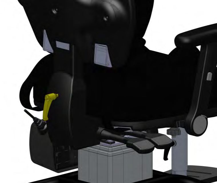
STOP!
LAP STRAPS & HARNESSES SAFETY NOTICE
Lap straps and harnesses must be appropriate and safe for the user and the
users clothing.
Lap straps and harnesses must be checked every time the chair is used to ensure
they are fitted as prescribed by the clinician, take account of the users clothing
and are tightened so that the user cannot sustain injury. Checking the fit of lap
straps and harnesses must be done with the user in the chair and should be
undertaken as soon as the users sits in the chair.
4.0 UNPACKING YOUR INDIGO HILO SEATING SYSTEM
STOP!
If in any doubt, ALWAYS seek ADVICE.
Always turn hand wheels, levers and screws clockwise to tighten or anti-
clockwise to loosen.
When delivered the product will be
supplied with the back rest (A) removed.
Unwind lever (C) and insert back rest (A)
into the back mechanism (B) – ensure it
is inserted fully.
Tighten lever (C) to secure the back rest
(A) into place.
If you have specified accessories at the
time of order, your IndiGO HiLo may be
supplied with these factory fitted.
Alternatively, please refer to Section 6.0
for details of how to fit and adjust your
accessories prior to use
4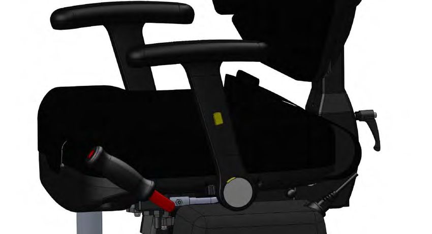
STOP!
If you believe this product to be faulty – DO NOT USE
Contact: Smirthwaite Ltd
T: +44 (0)1626 835552
F: +44 (0)1626 835428
E: enquiries@smirthwaite.co.uk
5.0 SETTING UP AND ADJUSTING YOUR INDIGO HILO SEATING
SYSTEM
STOP!
If in any doubt, ALWAYS seek ADVICE.
Always turn hand wheels, levers and screws clockwise to tighten or anti-clockwise
to loosen.
5.1 SEAT ADJUSTMENTS
3 adjustments can be made to the seat; depth, height and tilt.
5.1.1 DEPTH
1
To move the seat base backwards or forwards:
Locate the 2 hand wheels (1) underneath the seat base and loosen them.
Slide seat to the desired position.
Ideally allow 25mm gap between the back of knee and the edge of the seat.
Tighten the 2 hand wheels to secure in position.
5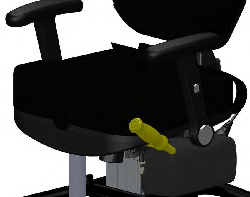
5.1.2 HEIGHT
2
The height of the chair can be altered by using the ‘Actuator Control Pad’ (2) which is
hooked onto the push handle of the chair. This pad can be unhooked and can be moved
to a more suitable position if required.
Push either the ‘Up’ arrow or the ‘Down’ arrow to move the chair to the required height.
Only press one arrow button at a time.
5.1.3 TILT IN SPACE
3
To adjust the tile angle of the seat:
Lift the front lever (3) on the side of the chair to unlock the tilt mechanism.
Adjust the seat tilt to the desired position.
Push the lever back down to lock the seat in the desired position.
6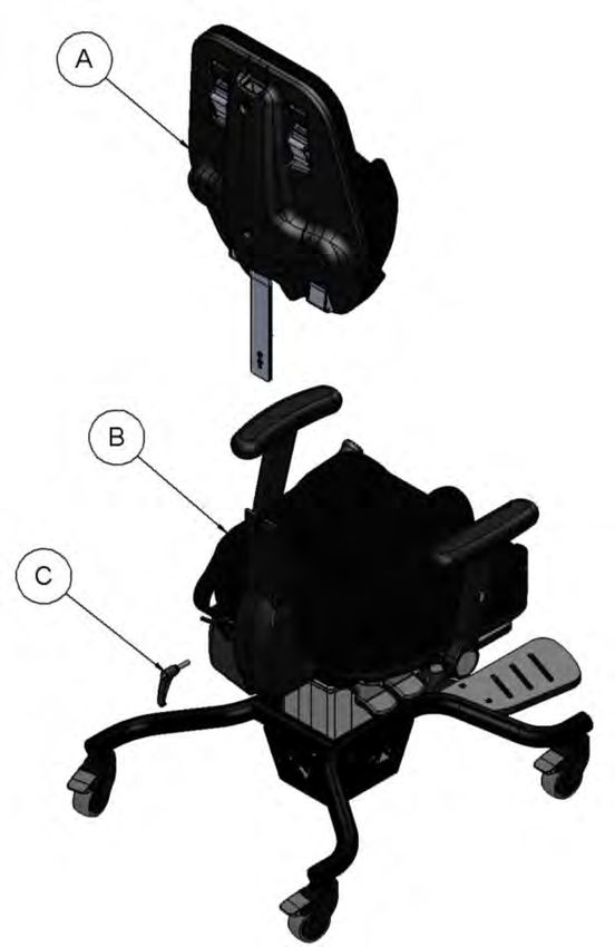
5.2 BACKREST ADJUSTMENTS
5.2.1 BACK RECLINE (ANGLE)
4
To adjust the angle of the backrest:
Lift the back lever (4) on the side of the chair to unlock the backrest tilt mechanism.
Adjust the back rest to the desired angle.
Push the lever back down to lock the back rest in position.
5.2.2 BACK REST HEIGHT
5
To adjust the height of the backrest:
Locate the lever lock on the back of the chair (5) and loosen it.
Slide the backrest up or down to the desired position.
Tighten the lever lock to secure the backrest in position.
7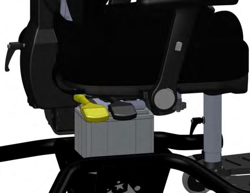
5.2.3 BACK LUMBAR PROMPT
6
To set the lumbar support, insert the supplied 4mm hex key into the central socket on the
back of the chair (6). Turn clockwise or anti-clockwise to set the lumbar support to the
required depth for the user.
5.2.4 THORACIC SUPPORT
7
Each thoracic support can be set independently by inserting the provided 4mm hex key into
either of the outer sockets on the back of the chair (7). Turn clockwise or anti-clockwise to
set each thoracic to the required angle for the user.
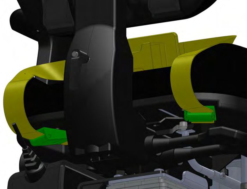
85.3 ARMRESTS
The armrests can be rotated out of the way to aid in the transfer of the user. Also the height
of the armrests can be adjusted.
8
9
ARMREST UP
ARMREST DOWN
5.3.1 HEIGHT
To raise or lower the armrests:
Press and hold the button midway up the outside face of the armrest (8).
Slide the armrest up or down slightly and release the button.
Continue to move the armrest up or down until the button ‘clicks’ out.
Repeat this step until the armrest is at the desired height.
Repeat for the other armrest.
95.3.2 ROTATION
To rotate the armrests out of the way:
Press and hold the button towards the base of the armrest (9).
Push the armrest backwards slightly and then release the button.
Continue to push the armrest backwards until the button ‘clicks’ out and the armrest is
in its lowered position.
To raise the armrests, push the button back in and rotate the armrest upwards.
Release the button and continue to rotate the armrest upwards until the button ‘clicks’
out and the armrest in in its up position.
5.4 BRAKING SYSTEM
5.4.1 USER OPERATED BRAKES
10
To apply the brakes, simply push the lever (10) downwards.
The brakes can then be locked in the ‘on’ position by parking the lever – simply push the
lever away from the seat cushion when it has reached its fully downward position.
To release the brakes, pull the lever toward the seat to release from its park position.
The lever is sprung-loaded; once it is released it will automatically return to its top
position.
Note: The brake lever can be on either side of the chair depending on the order.
105.4.2 CARER OPERATION
The IndiGO has been designed to permit any of the castors to be independently applied or
released by a carer, using each individual castor foot pedal. For instructions on how to use
the castor brakes see section ‘3.0 For your Safety’.
IMPORTANT!
If the user is having difficulty operating the brake system, check that the brake
pedal on each castor is in the ‘unbraked’ position.
5.4.3 BRAKE SYSTEM ADJUSTMENT
11
Adjustment of the brake mechanism is possible by rotating the adjustment knob (11)
that can be found underneath the seat base.
The IndiGO will be supplied pre-adjusted for optimum use; adjustment is only needed if
the mechanism performance degrades over long term use.
115.5 PELVIC LAP STRAP
5.5.1 BUCKLE
B
A
The IndiGO HiLo is supplied with a 2-point pelvic padded lap strap as standard.
The buckle is secured by pushing the male plug (A) into the female receiver (B).
To release the buckle, press both sides of the male plug and pull apart.
5.5.2 LENGTH ADJUSTMENT
12
13
To alter the length of the pelvic strap (12), simply adjust the amount of strap that is
fed through the cam-lock fasteners (13), which are located under the seat base at
the rear.
The steps to operate the cam lock can be seen in the above diagram.
126.0 OPTIONAL ACCESSORIES – FITMENT AND ADJUSTMENT
1. Multi-grip head rest
2. Flat head rest
3. Pommel
4. Flip-up footrest
136.1 HEADRESTS
14
6.1.1 FITMENT
Insert the stem of the headrest (14)
into the socket on the rear of the seat
back (15).
Take the supplied M6 x 20mm screw
(16) and washer (17) and insert the
15
screw through the aperture (18) and
into the insert located in the head rest
stem. 18
Tighten the screw with the supplied 17
4mm hex key.
16
6.1.2 HEADREST HEIGHT
The height of the headrest can be altered
in 2 stages.
Using the supplied hex key, loosen the
bolt on the back of the padded 19
headrest assembly (19).
Slide the headrest to the desired
position and tighten the bolt to secure
16
in place.
Using the supplied hex key, loosen the
M6 x 20 screw used for the fitment of
the headrest assembly (16)
Slide the whole headrest assembly to
the desired position and tighten the
screw to secure in place.
146.1.3 DEPTH AND ANGLE
To change the depth and/or angle of the
headrest:
Loosen the two lever locks (20).
Slide/angle the headrest to desired 20
position.
Tighten the two lever locks (20) to
lock.
6.1.4 HEADREST PROFILE/SHAPE – (MULTI GRIP HEAD REST ONLY)
To alter the profile (shape) of the
headrest:
Locate and unzip the cover of the 21
headrest.
Using the hex key, loosen the bolts
that secure the individual headrest
elements (21).
Position/shape the headrest elements
to suit your client’s needs.
Tighten the headrest elements (21) to
lock into the desired profile (shape).
Zip the cover shut on the headrest to
complete.
156.2 FLIP-UP FOOTREST
6.2.1 FITMENT
22 22
The foot rest assembly is attached to the underside of the seat base by 6 screws (M6 x
16mm). Four of these will already be fitted to the underside of the seat by the factory
located toward the front of the chair (22).
Using the hex key provided, ensure the four screws fitted to the underside of the seat
are loose.
Offer up the footrest (23) to the
underside of the seat and slide
forward. The slots in the front
of the footrest are to engage
with the screws mentioned in
the previous step.
Insert 2 further screws (24) at
the rear and tighten using the
supplied hex key. 24 23
Tighten the 4 screws at the
front of the footrest using the
supplied hex key.
Note: Electric HiLo Chassis
not shown for clarity
166.2.2 HEIGHT
25
To adjust the height of the footrest:
Locate the lever lock on the back side of the footrest assembly (25) and loosen it.
Slide the footrest assembly up or down to the desired position.
Tighten the lever lock to secure the footrest in position.
Each footrest board can be flipped up and stored vertically to aid transfer in and out of
the chair.
6.3 POMMEL
Insert the Pommel (26) through
the slot at the front of the seat
base.
Insert the grip knob (27) though
the base of the chair and into the
pommel.
Tighten the grip knob to secure.
Note: If the footrest is attached, the 26
grip knob will have to go through the
footrest, then the base and then into
the pommel.
27
177.0 CARE AND MAINTENANCE
IMPORTANT!
CLEANING IS RECOMMENDED ON A REGULAR BASIS
Clean wooden parts and upholstery with a damp cloth and mild detergent.
Clean metalwork with a damp cloth.
Stubborn marks on the woodwork or cushions should be cleaned using a soft brush
Do not soak or immerse the product in water
Store the product in a cool dry place and out of direct sunlight
DO NOT use bleach, solvents, abrasives, synthetic detergents, wax polishes, antibacterial
sprays or wipes
Operating temperature for the actuator is +5°C - +40°C
The actuator should be used for no more than 2 minutes at a time followed by a
downtime of at least 18 minutes.
For further information, please refer to your regional healthcare cleaning guidelines
7.1 CHARGING THE BATTERY
Apply the brakes to the castors before charging. Also do not use the chair whilst
charging.
When the battery is low a buzzer will sound. When this happens plug the charging cable
into the socket on the battery pack assembly.
Plug the other end of the cable into a mains socket and turn on to begin charging the
battery.
The battery will become fully charged in approximately 6 hours.
187.2 DAILY CHECKS
Check for signs of wear, tear or damage
Check for missing parts
Check that all screws are present and tighten correctly, and are not cross-threaded or
damaged
Check all straps for fraying, and that buckles are not missing/damaged
Check that the castors run freely and the brakes on each castor function correctly
Check that the high-low feature operates correctly
Check that the tilt-in-space feature operates correctly
Check that the battery is adequately charged.
Check that the footplate is set to the correct height for the client, and that it is securely in
place. (if footrest attachment used)
7.3 ANNUAL SERVICE
The IndiGO HiLo Seating System should be serviced annually. Servicing must only be
undertaken by a Smirthwaite Ltd service engineer, or by a Smirthwaite Ltd trained
representative.
7.4 NOMINAL SERVICE LIFE
Your product has a nominal service life of 7 years, during which full post-sales support will
be available with regard to spares and servicing.
Product service life has been determined based upon the design complexity of product, and
the anticipated exposure to normal use.
Good practice dictates all Smirthwaite Ltd products have been designed and manufactured
to high levels of safety and quality, and will meet requirements of normal use when
maintained in line with our servicing recommendations.
19STOP!
If the product has been out of use for an extended period of time (6 months or
more) it should always be serviced prior to being re-issued.
If the product has been subjected to ‘heavy’ or ‘constant’ use, the service
should be reduced to half the recommended period.
Constant and/or heavy use is considered to be:
Daily use above 7 hours duration
Weekly use above 5 days duration
Monthly use above 10 months per year
Use by a client who is at 90% to 100% of the maximum weight limit of the
product. The maximum weight limit must NEVER be exceeded
Use by a client who is extremely active, either voluntarily or involuntarily
7.5 EXTENDING NOMINAL SERVICE LIFE
At Smirthwaite Ltd we are proud to produce products that have a reputation for quality and
durability.
We believe our products have the potential to provide benefits to our clients beyond the
nominal service life documented above.
We will continue to provide full support beyond the nominal service life provided the
following conditions are met:
1. A full service schedule has been maintained.
2. A full service and inspection is undertaken at the end of the nominal service life
period.
3. The product is subsequently serviced annually (or biannually if under
‘heavy/constant’ use conditions).
4. Smirthwaite Ltd reserves the right to limit support where parts/components are no
longer available.
207.6 DOCUMENTATION/RECORDS
It is the responsibility of the current equipment owner to ensure the ‘Instructions for
Use’ manual and any further manuals for accessories fitted to the equipment are
handed over to the new owner at the time of exchange/sale.
It is the responsibility of the current equipment owner to ensure the service and
inspection record form is kept up to date.
7.7 PRODUCT CONFIGURATION
Smirthwaite Ltd will document and maintain a record of the original product
configuration at the time of first sale.
Smirthwaite Ltd will not be held responsible for any subsequent changes to this
configuration unless authorized to do so in writing by Smirthwaite Ltd.
It is the equipment owner’s responsibility to maintain their own records of changes to
the equipment configuration and to be able to provide such records to subsequent
owners to maintain traceability. We recommend an inspection/service by a Smirthwaite
Ltd service engineer (or Smirthwaite Ltd trained engineer) whenever a significant change
is made to product configuration to ensure the product is safe to use. If in any doubt,
ALWAYS seek ADVICE.
IMPORTANT REMINDER!
DO NOT fit parts or accessories of other manufacturers to this product unless
authorized to do so in writing by Smirthwaite Ltd.
Any servicing or repairs required must be carried out by Smirthwaite Ltd (or a
Smirthwaite Ltd trained engineer).
If you believe this product to be faulty – DO NOT USE
Contact: Smirthwaite Ltd
T: +44 (0)1626 835552
F: +44 (0)1626 835428
E: enquiries@smirthwaite.co.uk
If in any doubt, ALWAYS seek ADVICE.
218.0 WARRANTY & SERVICE
Smirthwaite Ltd warrants the products detailed on your order to be free from defects in
materials and workmanship for a period of 2 years from date of delivery. If a fault develops
during the period, please call Customer Services by email or telephone 01626 835552 who
will advise you on the best course of action. Possible action may be for us to arrange to send
out one of our Service Engineers, or have the goods returned to us. Should a repair not be
possible within the guarantee period we will replace the product for new or nearest
equivalent product. In the unlikely event that we cannot repair or exchange we will refund
in full.
This warranty is for the UK only. The warranty excludes faults due to accident, neglect,
misuse, not following the Instructions and normal wear and tear. This warranty is in addition
to your legal rights. Goods will only be collected from the original delivery address.
A charge may be made where the goods cannot be repaired under the terms of the
warranty. You will be advised before this is made.
T: +44 (0)1626 835552 E: info@smirthwaite.co.uk
9.0 CONTINUOUS IMPROVEMENT
Smirthwaite Ltd are committed to continuous improvement to their product range. Should
you have any suggestions or comments please contact our product design department,
using enquiries@smirthwaite.co.uk
Smirthwaite Ltd reserves the right to change the specification or material without prior
notice.
For catalogues, help and further information on our products please contact us at:
Smirthwaite Ltd
16 Wentworth Road
Newton Abbot
Devon, TQ12 6TL
T: +44 (0)1626 835552
F: +44 (0)1626 835428
E: enquiries@smirthwaite.co.uk
2210.0 WARRANTY & AFTERSALE
10.1 PRODUCT INFORMATION
Model:
Size:
Date of Manufacture:
Serial Number:
Final Inspection:
10.2 SERVICE & INSPECTION RECORD FORM
Date Procedure Service Personnel
23Smirthwaite Ltd, 16 Wentworth Road, Newton Abbot, Devon, TQ12 6TL T: +44 (0)1626 835552 F: +44 (0)1626 835428 E: enquiries@smirthwaite.co.uk
You can also read