INDOOR CLEANING Dishwasher Installation Manual - KDW - Hestan Outdoor
←
→
Page content transcription
If your browser does not render page correctly, please read the page content below

INDOOR CLEANING
    Dishwasher
        KDW

 Installation Manual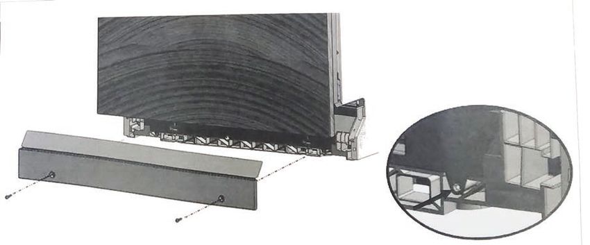
EN

             IF THE INFORMATION IN THIS MANUAL IS NOT FOLLOWED
                EXACTLY, A FIRE OR EXPLOSION MAY RESULT CAUSING
                 PROPERTY DAMAGE, PERSONAL INJURY, OR DEATH.

       Do not store or use gasoline or other flammable vapors and liquids in the vicinity of
       this or any other appliance.
       Installation and service must be performed by a qualified installer or service agency.
       DO NOT REPAIR, REPLACE OR REMOVE ANY PART OF THE APPLIANCE UNLESS
       SPECIFICALLY RECOMMENDED IN THE MANUAL. IMPROPER INSTALLATION,
       SERVICE OR MAINTENANCE CAN CAUSE INJURY OR PROPERTY DAMAGE.
       REFER TO THIS MANUAL FOR GUIDANCE. ALL OTHER SERVICING SHOULD BE
       DONE BY A QUALIFIED TECHNICIAN.

      READ THESE INSTRUCTIONS CAREFULLY AND COMPLETELY BEFORE
      INSTALLING OR USING YOUR APPLIANCE TO REDUCE THE RISK OF FIRE,
      BURN HAZARD, OR OTHER INJURY. KEEP THIS MANUAL FOR FUTURE
      REFERENCE.

      SAFETY DEFINITIONS

                                   THIS INDICATES THAT DEATH OR SERIOUS INJURY MAY
                                   OCCUR AS A RESULT OF NOT OBSERVING THIS WARNING

                                   THIS INDICATES THAT MINOR OR MODERATE INJURY MAY
                                   OCCUR AS A RESULT OF NOT OBSERVING THIS WARNING.

                                   THIS INDICATES THAT DAMAGE TO THE APPLIANCE OR
                                   PROPERTY MAY OCCUR AS A RESULT OF NOT OBSERVING
                                   THIS WARNING.

     INSTALLER: LEAVE THIS MANUAL WITH THE OWNER OF THE APPLIANCE.
     HOMEOWNER: RETAIN THIS MANUAL FOR FUTURE REFERENCE.

      ©2019 Hestan Commercial Corporation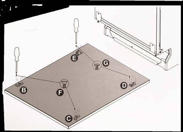
TABLE OF CONTENTS
    1    SAFETY PRECAUTIONS - BEFORE YOU BEGIN
    2    MODEL NUMBERS
    2    RATING LABEL                                                                                         EN
    2    REGULATORY / CODE REQUIREMENTS
    3    PRODUCT WARNINGS / SAFETY
    4    LOCATION AND PREPARATION
    8    INSTALLATION
    14   OVERLAY PANEL
    16   FINAL STEPS
    18   SERVICE

SAFETY PRECAUTIONS - BEFORE YOU BEGIN
When properly cared for, your Hestan appliance will provide safe, reliable service for many years.
When using this appliance, basic safety practices must be followed as outlined below.
IMPORTANT: Save these instructions for the local Utility Inspector’s use.
INSTALLER: Please leave these Installation Instructions with the owner.
OWNER: Please retain these Installation Instructions for future reference.
This appliance is NOT designed for installation in manufactured (mobile) homes or recreational
park trailers. Do NOT install this appliance outdoors.

ELECTRICAL SHOCK HAZARD
Disconnect power before installing or servicing appliance. Failure
to do so can result in death or electrical shock.

ELECTRICAL GROUNDING
•    This appliance must be grounded. Grounding reduces the risk of
     electric shock in the event of a short circuit.
•    DO NOT ground to a gas pipe.
•    DO NOT use an extension cord with this appliance.
•    DO NOT have a fuse in the NEUTRAL or GROUNDING circuit. A fuse in the NEUTRAL or
     GROUNDING circuit could result in an electrical shock.

                                                                     2019 Hestan Commercial Corporation   1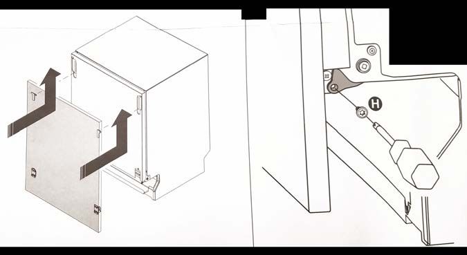
MODEL NUMBERS

         DISHWASHER MODELS
EN
                                                                              CIRCUIT BREAKER
          MODEL NO.               DESCRIPTION
                                                                              REQ'D
          KDW24                   24" Dishwasher, Stainless Steel Door        15 Amp
          KDW24-OV                24" Dishwasher, Overlay Door                15 Amp
          KDW24-XX                24" Dishwasher, Color Door                  15 Amp

         RATING LABEL
         The rating label contains important information about your Hestan
         appliance such as the model, serial number, and electrical rating.
         The rating label is located on the right side of the door edge.
         If service is necessary, contact Hestan Customer Care with the
         model and serial number information shown on the label.

                                                                                Rating Label Location

                       Typical Rating Label

         REGULATORY / CODE REQUIREMENTS
         Installation of this dishwashing appliance must be made in accordance with local codes. In the
         absence of local codes, this unit should be installed in accordance with the National Electrical
         Code and local codes.
         This appliance must be electrically grounded in accordance with local codes or in the absence of
         local codes with the National Electrical Code ANSI/NFPA 70, or Canadian Electrical code CSA
         C22.1.

     2   ©2019 Hestan Commercial Corporation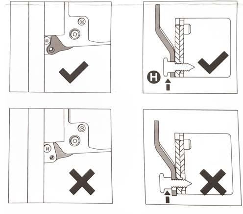
PRODUCT WARNINGS / SAFETY

                                                                                              EN
THIS MANUAL IS AN INTEGRAL PART OF THE APPLIANCE:
IT MUST ALWAYS BE KEPT INTACT TOGETHER WITH THE DISHWASHER. BEFORE
USING THE APPLIANCE, CAREFULLY READ ALL THE INSTRUCTIONS CONTAINED IN
THIS MANUAL. INSTALLATION MUST BE PERFORMED BY A QUALIFIED TECHNICIAN,
IN COMPLIANCE WITH LOCAL CODES. THIS APPLIANCE IS INTENDED FOR DOMESTIC
USE AND SIMILAR APPLICATIONS SUCH AS THE STAFF KITCHENS OF SHOPS, OFFICES
AND OTHER WORKPLACES, INSTITUTIONS, AND FOR THE USE OF GUESTS AT HOTELS,
HOSTELS, BED AND BREAKFAST ESTABLISHMENTS AND OTHER RESIDENTIAL FACILITIES.
THE APPLIANCE IS DESIGNED FOR THE FOLLOWING PURPOSE: WASHING AND DRYING
DISHES. ANY OTHER USE SHALL BE CONSIDERED IMPROPER. THE MANUFACTURER
DECLINES ALL RESPONSIBILITY FOR USES OTHER THAN THOSE DESCRIBED ABOVE.
THIS APPLIANCE IS NOT SUITABLE FOR USE ON BOATS, RECREATIONAL VEHICLES OR
THE LIKE. DISHWASHERS CERTIFIED FOR DOMESTIC USE ARE NOT SUITABLE FOR
COMMERCIAL APPLICATIONS.
THE RATING LABEL FEATURING THE TECHNICAL DATA, SERIAL NUMBER AND MARKINGS
IS VISIBLY POSITIONED ON THE RIGHT EDGE OF THE DOOR. THE RATING LABEL MUST
NEVER BE REMOVED.

                     CHECK THAT THE VOLTAGE, FREQUENCY AND PROTECTION
                     OF THE DOMESTIC MAINS POWER SUPPLY MATCH THE
                     RATINGS ON THE RATING PLATE OF THE APPLIANCE.

DO NOT LEAVE DISCARDED PACKAGING MATERIALS UNSUPERVISED WITHIN THE
HOME. SEPARATE THE VARIOUS PACKAGING MATERIALS AND TAKE THEM TO THE
NEAREST SORTED WASTE COLLECTION CENTRE. KEEP CHILDREN, PHYSICALLY AND/
OR MENTALLY IMPAIRED ADULTS, AND ANIMALS AWAY FROM PACKAGING WASTE;
DANGER OF SUFFOCATION.
BEFORE PROCEEDING WITH INSTALLATION, TURN OFF THE CIRCUIT BREAKER SERVING
THE WORK AREA.
THE APPLIANCE MUST BE PROVIDED WITH A GROUND CONNECTION IN ACCORDANCE
WITH THE ELECTRICAL SAFETY REGULATIONS IN FORCE. IF IN DOUBT, HAVE THE
SYSTEM CHECKED BY A QUALIFIED ELECTRICIAN. THE MANUFACTURER DECLINES
ALL RESPONSIBILITY FOR DAMAGE TO PERSONS OR PROPERTY RESULTING FROM THE
FAILURE TO GROUND THE APPLIANCE OR FROM A DEFECTIVE GROUND CONNECTION.

                      DURING INSTALLATION, TAKE CARE NOT TO INJURE
                      YOURSELF ON THE SHARP EDGES OF THE APPLIANCE; WEAR
                      SAFETY GLOVES.

DO NOT USE APPLIANCES WHICH HAVE BEEN DAMAGED DURING TRANSIT! IF
IN DOUBT, CONSULT YOUR DEALER. THE APPLIANCE MUST BE INSTALLED AND
CONNECTED IN ACCORDANCE WITH THE INSTRUCTIONS PROVIDED BY HESTAN OR BY
A QUALIFIED TECHNICIAN.
DO NOT OPERATE THE DISHWASHER UNLESS ALL THE OUTER PANELS HAVE BEEN
POSITIONED CORRECTLY. IMMEDIATELY AFTER INSTALLATION, BRIEFLY TEST THE
APPLIANCE FOLLOWING THE INSTRUCTIONS INDICATED ON PAGE 18. IF THE
DISHWASHER FAILS TO OPERATE CORRECTLY, DISCONNECT IT FROM THE ELECTRICAL
POWER SUPPLY AND CALL HESTAN CUSTOMER SERVICE. DO NOT ATTEMPT TO REPAIR
THE APPLIANCE.

                                                     2019 Hestan Commercial Corporation   3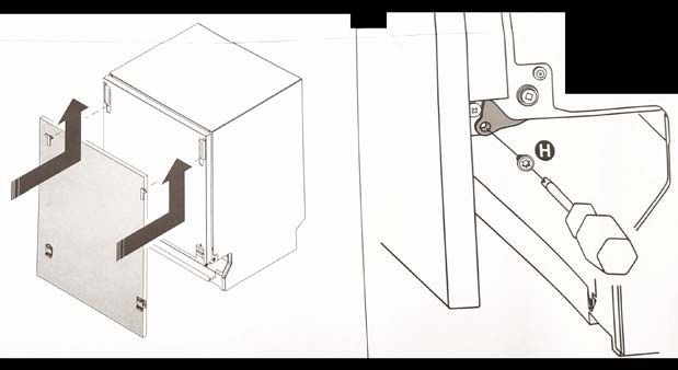
PRODUCT WARNINGS / SAFETY (CONT.)

                                           DO NOT USE EXTENSION CORDS, ADAPTORS OR SHUNT
                                           CONNECTIONS IN ORDER TO AVOID THE POSSIBILITY OF
EN                                         OVERHEATING OR BURNING, WITH CONSEQUENT FIRE
                                           HAZARD.

                                   THE MANUFACTURER DECLINES ALL RESPONSIBILITY FOR DAMAGE
                                   TO PERSONS, ANIMALS OR PROPERTY RESULTING FROM FAILURE
                                   TO OBSERVE THE ABOVE PRECAUTIONS, FROM TAMPERING WITH
                                   EVEN A SINGLE COMPONENT OF THE APPLIANCE, OR FROM THE
                                   USE OF NON-ORIGINAL SPARE PARTS.
         IF IN DOUBT ABOUT THE CONTENTS OF THIS MANUAL, CONTACT HESTAN CUSTOMER
         CARE.

         LOCATION AND PREPARATION
         UNPACKING AND PLACEMENT
         Remove the outer carton and packing materials, but do not remove the plastic film covering
         the stainless-steel surfaces. This film protects the finish from scratches until the appliance is
         installed in its final position.
         Materials packaged with the dishwasher include this manual, the Use and Care Manual, and the
         installation kit.
         •   The kit may include supplemental instructions for assembly.
         OVERLAY MODELS
         Dishwashers configured for overlay doors (rather than color or stainless steel finish) will include
         a full-size template for the door overlay panel, as well as hardware and fasteners for the overlay.
         The template includes pictoral instructions for preparing and installing the overlay panel.
         HANDLING
         The unit is heavy and should be handled with care. Use proper safety equipment, such as gloves
         and 2 persons to move the appliance into position to avoid injury and to avoid damage to the
         fioor or the appliance itself.

                                   DO NOT USE A HAND TRUCK OR DOLLY ON THE FRONT OR REAR
                                   OF THE DISHWASHER. HANDLE AND MOVE FROM THE SIDES ONLY.
                                   Do not lift or carry the appliance by the door or handle. This could damage
                                   the door hinges.

         PREPARATION
         Before moving the dishwasher, protect any finished flooring and secure the door closed to
         prevent damage. DO NOT lift the dishwasher by the door handle.
         Make sure that power can be provided to the location selected.

     4   ©2019 Hestan Commercial Corporation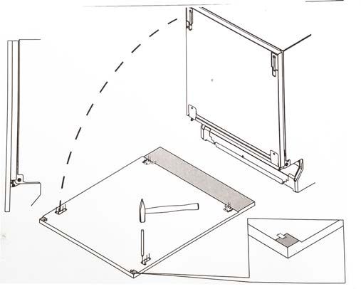
LOCATION AND PREPARATION (CONT.)

TOOLS
The following tools are needed for the installation of the dishwasher:                                         EN
•   Tape measure and straight edge or ruler
•   Pencil
•   T20 Torx driver
•   Philips screw driver
•   Level
•   Plumbing pliers
•   Drill and drill bits
•   Safety gloves and goggles

STEPS FOR INSTALLATION
The following pages provide the necessary information for proper installation of the dishwasher
and are arranged as follows:
•   Contents of installation kit
•   Installation cutout dimensions and required clearances
•   Electrical, water, and drain connections.
•   Preparation and installation of overlay panels (-OV units only)
•   Final installation
•   Leak inspection and testing.

                                                                      2019 Hestan Commercial Corporation   5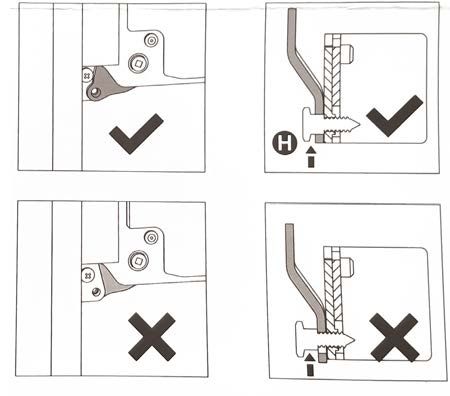
LOCATION AND PREPARATION (CONT.)

         INSTALLATION KIT SUPPLIED WITH DISHWASHER
EN       The kit supplied with the dishwasher comprises:
         (KDW24-OV model includes items B - G)

             Key         Used On                                    Item
             A, A1         All         steam guard and adhesive
             B, C        -OV only      hooks for door panel
             D, E        -OV only      brackets for door panel
               F         -OV only      8 screws for securing the door panel hooks
               G         -OV only      8 screws for securing the door panel brackets
               H         -OV only      2 torx screws for securing the door to the brackets
                I          All         upper screws
               L           All         screws for securing the dishwasher to the adjacent cabinets
              M            All         screw caps

         Not pictured: template for overlay panel, -OV models only.

                                                                      x1

                                                            x1

     6   ©2019 Hestan Commercial Corporation
LOCATION AND PREPARATION (CONT.)

PRODUCT / CUT-OUT DIMENSIONS
PRODUCT DIMENSIONS:                                                                                         EN

 A (minimum height)             B (Width)             C (depth)
33-7/8" [86 cm]           23-9/16" [59.8 cm]   21-11/16" [57 cm]

CUT-OUT DIMENSIONS:

      D (height)                  E (width)            F (depth)
34” (min) [86.3 cm]       23-9/16" - 23‑5/8"   22-5/8” (min)
                          [59.8 - 60.0 cm]     [57.5 cm]

            D
                                                                            A
                                         E
                      F
                                                  C          B

            D
                                                                           A
                                         E
                      F
                                                  C          B

                                                                   2019 Hestan Commercial Corporation   7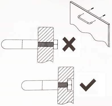
INSTALLATION

                                          DURING INSTALLATION, TAKE CARE NOT TO INJURE YOURSELF
EN                                        ON THE SHARP EDGES OF THE APPLIANCE.
         Remove the polystyrene rack blocks. Position the appliance in the chosen installation position.
         The sides and rear of the appliance can lie against kitchen units or walls. If the dishwasher
         is installed next to a heat source, separate it with a heat insulating panel in order to prevent
         overheating and malfunctions.

                                          BUILDING-IN A DISHWASHER BELOW A COOKTOP IS
                                          ABSOLUTELY FORBIDDEN.
         MAKE SURE THE DISHWASHER HAS BEEN CORRECTLY INSTALLED AND GROUNDED
         BY A QUALIFIED ELECTRICIAN. THIS SAFETY REQUIREMENT MUST BE MET. IN CASE
         OF DOUBT, CALL IN A QUALIFIED ELECTRICIAN. THE MANUFACTURER DECLINES ALL
         RESPONSIBILITY FOR DAMAGE TO PERSONS OR PROPERTY RESULTING FROM THE
         FAILURE TO GROUND THE APPLIANCE OR FROM A DEFECTIVE GROUND CONNECTION.
         BEFORE PROCEEDING WITH INSTALLATION, TURN OFF THE CIRCUIT BREAKER THAT
         WILL SUPPLY THE APPLIANCE.

         LEVELING
         Level the appliance using the adjustable feet on the bottom.
         Use a level and adjust the feet until the dishwasher is perfectly level. Leveling is vital for ensuring
         correct dishwasher operation.
         Make sure to leave a gap of at least 7/64” [3mm] between the top of the dishwasher door and the
         bottom surface of the countertop.

     8   ©2019 Hestan Commercial Corporation
INSTALLATION (CONT.)
ELECTRICAL AND WATER CONNECTIONS
Install the dishwasher to allow ease of access to the electrical and water connections through the EN
adjacent cabinetry. These connections must never be behind the dishwasher. The inlet and drain
hoses can be pointed in any direction but make sure that they are not bent, crushed or too tight.
Tighten the ring nut after pointing the hose in the required direction.
The illustration below indicates the lengths of hoses and power cord for connection purposes.
FIRE HAZARD!
DO NOT COVER OR CRUSH THE CORD PLUG.
A through hole with a diameter of
at least 2‑1/4” (57 mm) is required
to pass the hoses and power cord.
• Make sure there are no rough
edges that could damage the
power cord or hoses. A
• If the dishwasher is installed in
B D
a metal cabinet or enclosure,
protect the edge of the through
hole for the hoses and power C
cord with a grommet. A = 47” [120 cm]
• Do not use extension cords B = 59” [150 cm]
when making the electrical C = 63” [160 cm]
connection as these do not D = min. 16” [40 cm]
guarantee safety.
INSTALLING THE DISHWASHER IN A NARROW SPACE MAY BEND OR CRUSH THE POWER
CORD. TAKE GREAT CARE IN ORDER TO REDUCE THE POSSIBILITY OF DAMAGING THE
POWER CORD WHEN INSTALLING OR REMOVING THE APPLIANCE.
CONNECTING THE WATER SUPPLY
PREVENTING THE RISK OF CLOGGING OR DAMAGE:
IF THE PLUMBING IS NEW OR HAS NOT BEEN USED
FOR A LONG TIME TIME, BEFORE CONNECTING TO A
THE WATER SUPPLY, CHECK THAT THE WATER IS
CLEAR AND FREE OF DEBRIS TO PREVENT DAMAGE
TO THE APPLIANCE. THE DISHWASHER MUST
ALWAYS BE CONNECTED TO THE THE WATER
SYSTEM WITH NEW HOSES. OLD OR USED HOSES
MUST NEVER BE RE-USED.
2019 Hestan Commercial Corporation 9INSTALLATION (CONT.)
CONNECTING TO A WATER VALVE
EN Connect the inlet hose to a threaded 3/4” water valve using
the supplied filter. Firmly secure the hose by tightening its
ring nut with your hands; finish by tightening another 1/4
turn using a pair of plumbing pliers.
The dishwasher can be filled with water at a temperature of
less than 140° F [60° C]. If the appliance is filled with hot
water, washing times will be reduced by about 20 minutes,
but efficiency will be slightly impaired.
• Recommended temperature: 120° F [49° C], max 140° F
[60° C].
• Recommended water pressure: 7-130 PSI [0.5 - 9 bar]. If
the pressure is too high, use a pressure reducer.
A rubber hose connected to a sink spray may burst if
installed on the same pipes feeding the dishwasher. If your sink is fitted with this accessory,
remove the hose and plug the hole.
DO NOT CUT THE INLET HOSE.
If the hose is cut, the dishwasher will not work, water will
leak and you may be injured. If the hose is too long, wind it
up neatly and place it behind the appliance. The cable
harness and electrical components must not come into
contact with the hydraulic system and the water inlet and
drain hoses.
When connecting the dishwasher drain hose to the sink make sure that the hose is not bent in
order to prevent cracks or breakages that could damage it.
A
10 ©2019 Hestan Commercial CorporationINSTALLATION (CONT.)
CONNECTING TO A WASTE DISPOSAL UNIT WITH AN AIR GAP
MAKE THE CONNECTION UPLINE FROM THE SIPHON OF THE DRAIN LINE AND AT EN
LEAST 15-3/4” [40 cm] ABOVE THE FLOOR ON WHICH THE DISHWASHER WILL BE
INSTALLED.
C
1. Remove the cover of the waste
disposal unit (A).
2. Connect the dishwasher drain hose A
(B) to the air gap (C) using the wide D H
spring clamp (D) F
G H
3. If necessary, cut the end of the E
dishwasher drain hose (E) (do not B
cut the corrugated section).
-- If the drain hose has been cut, use
a 1-1/2 to 2” [3.8 to 5 cm] screw
clamp*.
4. To connect the air gap (C) to the
waste disposal unit inlet (F) use a
rubber hose* (G) with spring or screw clamps (H)*
* Available from a plumbing store or home center.
CONNECTING TO THE AIR GAP WITHOUT A WASTE DISPOSAL UNIT
MAKE THE CONNECTION UPLINE FROM THE SIPHON OF THE DRAIN LINE AND AT
LEAST 15-3/4” [40 cm] ABOVE THE FLOOR ON WHICH THE DISHWASHER WILL BE
INSTALLED
C
1. Connect the dishwasher drain hose
(B) to the air gap (C) using the wide
spring clamp (D)
2. If necessary, cut the end of the D H
dishwasher drain hose (E) (do not G F
cut the corrugated section). E
-- If the drain hose has been cut, use B H
a 1-1/2 to 2” [3.8 to 5 cm] screw
clamp*.
3. To connect the air gap (C) to the
waste disposal unit inlet (F) use
a rubber hose* (G) with spring or
screw clamps (H)*
Available from a plumbing store or home center.
2019 Hestan Commercial Corporation 11INSTALLATION (CONT.)
CONNECTING TO A WASTE DISPOSAL WITHOUT AN AIR GAP
EN MAKE THE CONNECTION UPLINE FROM THE SIPHON OF THE DRAIN LINE AND AT
LEAST 15-3/4” [40 cm] ABOVE THE FLOOR ON WHICH THE DISHWASHER WILL BE
INSTALLED
1. Remove the cover of the waste disposal unit
(A). A
2. Connect the dishwasher drain hose (B) to the
waste disposal unit inlet (C), using the wide D C
spring clamp (D)*. E
3. Arrange the hose to form a high loop (E) as
shown in the illustration. This is required to B
prevent backflow of contaminated water into
the dishwasher. E: High loop 6-9”
[15-23 cm]
* Available from a plumbing store or home center.
.
CONNECTING TO A “T” UNION
MAKE THE CONNECTION UPLINE FROM
THE SIPHON OF THE DRAIN LINE AND AT
LEAST 15-3/4” [40 cm] ABOVE THE FLOOR
ON WHICH THE DISHWASHER WILL BE
INSTALLED.
1. Connect the dishwasher drain hose to
the “T” union of the drain using a 1-1/2 A
to 2” [3.8 to 5 cm] screw clamp.*
2. Arrange the hose to form a high loop
(A) as shown in the illustration. This
is required to prevent backflow of
contaminated water into the dishwasher. A: High loop 6-9”
[15-23 cm]
3. If necessary, cut the end of the
dishwasher drain hose (DO NOT cut the
corrugated section).
* Available from a plumbing store or home center.
CONNECTING TO THE POWER OUTLET
CHECK THAT VOLTAGE AND FREQUENCY OF THE OUTLET
MATCHES THE RATINGS ON THE RATING PLATE OF THE
APPLIANCE, WHICH IS POSITIONED ON THE INNER EDGE OF
THE DOOR.
IN THE EVENT OF DAMAGE TO THE SUPPLY CORD, HAVE IT
REPLACED BY THE MANUFACTURER OR AN AUTHORIZED
TECHNICIAN. THIS APPLIANCE MUST BE GROUNDED. IN CASE
OF A MALFUNCTION, THE GROUND REDUCES THE RISK OF
ELECTROCUTION BY PROVIDING THE ELECTRICAL CURRENT WITH AN ALTERNATIVE,
LESS RESISTANT PATH. THIS APPLIANCE IS FITTED WITH A POWER CORD CONTAINING
A GROUND WIRE AND PLUG. FIT THE PLUG INTO A SUITABLE OUTLET, INSTALLED AND
GROUNDED IN COMPLIANCE WITH LOCAL CODES.
BEFORE MAKING ELECTRICAL CONNECTIONS, TURN OFF THE
CIRCUIT BREAKER THAT WILL SERVE THE APPLIANCE.
12 ©2019 Hestan Commercial CorporationINSTALLATION (CONT.)
AN INCORRECTLY CONNECTED GROUND WIRE MAY
GENERATE THE RISK OF ELECTROCUTION. IF IN DOUBT AS TO
THE CORRECT GROUNDING OF THE APPLIANCE, CALL IN A EN
QUALIFIED ELECTRICIAN OR THE TECHNICAL ASSISTANCE
SERVICE. DO NOT CHANGE THE PLUG ATTACHED TO THE
APPLIANCE.
THE PLUG AT THE END OF THE POWER CORD AND THE
CORRESPONDING OUTLET MUST BE OF THE SAME TYPE AND
MUST CONFORM TO LOCAL REGULATIONS GOVERNING
ELECTRICAL APPLIANCES. NEVER REMOVE THE PLUG BY
PULLING ON THE CORD.
CONDENSATION PROTECTION
The steam guard protects the countertop from steam and
condensation when the door of the dishwasher is opened
at the end of the washing cycle.
Adhesive and screws are provided, to be used according
to installation requirements. See "INSTALLATION KIT
SUPPLIED WITH DISHWASHER" on page 6.
Mount the steam guard as follows:
MOUNTING THE STEAM GUARD WITH SCREWS
If the countertop can be drilled for screws, use screws to mount the steam guard.
1. Mark and drill pilot holes if needed.
2. Position the guard and install mounting screws.
MOUNTING THE STEAM GUARD WITH ADHESIVE
If the countertop can't be drilled for mounting screws, use
adhesive to mount the steam guard.
1. Clean the front 6” of the underside of the countertop
directly above the door.
2. Peel the protective layer from the adhesive surface.
3. Apply the steam guard, pressing the guard firmly in place
to get full contact of the adhesive onto the mounting
surface.
NEXT STEPS
If your dishwasher is an overlay model, continue with the
instructions in the OVERLAY PANEL section.
If you have a model with stainless-steel or colored door,
proceed to "FINAL STEPS" on page 18.
2019 Hestan Commercial Corporation 13OVERLAY PANEL (MODEL KDW24-OV)
OVERLAY PANEL PREPARATION
EN MOUNTING SUPPORT HOOKS AND BRACKETS
1. Place the provided template on the inner surface of the overlay panel.
2. Center the template on the panel and align it with the top edge, matching up the reference
locators (A).
3. Mark the position of the door hooks and brackets A
with a pencil.
4. Remove the template and use a drill with a suitable
bit to make pilot holes at the points marked on the
panel. A
• To avoid drilling too deep, use of a drill stop is
recommended.
5. Using a Phillips screwdriver, secure the door hooks (B, C) with the 8 supplied flat head screws
(items F) at the marked reference points.
6. Use the screwdriver to secure the lower
brackets (D, E) with the 8 supplied round
head screws (item G) at the marked
reference points.
14 ©2019 Hestan Commercial CorporationOVERLAY PANEL (CONT.)
MOUNTING HANDLE
The KDW24-OV model is not supplied with a door handle. Installation of customer's preferred EN
handle should be done according to instructions provided with the handle and according to good
practices.
The handle mounting screws must be countersunk or
recessed so they do not protrude above the overlay panel
surface.
ATTACH THE DOOR PANEL
Fit the hooks into their slots on the dishwasher, slide the panel upward, and install the bracket
screws (items H).
• Make sure that the screw shank (H) fits through the hole in the bracket as shown above.
• Make sure the dishwasher door, complete with panel, opens fully.
2019 Hestan Commercial Corporation 15FINAL STEPS
ADJUSTABLE BASE PLATE
EN An adjustable base plate is provided to protect the front of the dishwasher.
1. Install the spacers in the main plate (A, B above)
2. Position the plate (A) and install the screws (C)
A
C
C
3. Position the slider plate (D) so it is captured by the main plate (A) and can slide to the floor.
D
A
16 ©2019 Hestan Commercial CorporationFINAL STEPS (CONT.)
GASKETS
Before securing the dishwasher to the cabinets, attach the gaskets to the sides.
EN
1. Remove the protective tape from the adhesive surface.
2. Fix the gasket to the dishwasher, inserting it in the seat on the
sides towards the front
-- Make sure that the long side of the gasket, the one with the
holes for inserting the screws, is attached to the outside of
the dishwasher. (Figure 1 below.)
-- The holes in the long side must match the holes in the
dishwasher. (See A in Figure 2 below.)
Figure 3 shows the gasket in position.
Figure 2
Figure 1 Figure 3
3. Make sure the gasket adheres perfectly to the dishwasher.
4. Secure the dishwasher to the adjacent cabinetry or to the countertop above using the
supplied screws.
MAKE SURE THERE IS AT LEAST 1/8" [3 mm] CLEARANCE BETWEEN
THE TOP OF THE DOOR AND THE SURFACE ABOVE IT.
This operation secures the dishwasher to the adjacent cabinets or to the countertop.
5. Cover the side holes using the supplied plugs.
2019 Hestan Commercial Corporation 17FINAL STEPS (CONT.)
TEST OPERATION
Before starting a washing program, do the following: :
EN
1. Make sure the water supply valve is open.
2. Prepare the water softening system, according to the instructions in the Use & Care Manual,
"USING THE WATER SOFTENING SYSTEM" on page 18.
3. Add rinse-aid according to the instructions in the Use & Care Manual, "ADDING RINSE-AID
TO THE DISPENSER" on page 19.
AD D
Super/
Soak Crystal Delicate Daily Wash Select Salt Rinse Aid Energy Saver Quick Wash Delay Start
Sanitize
1/2 Load
Sanitize
2 3
ADD
Super/
Soak Crystal Delicate Daily Wash Select Salt Rinse Aid
Sanitize
1
Energy Saver Quick Wash Delay Start
1/2 Load
Sanitize
TURNING ON THE DISHWASHER
Press the on/off button (Item 1, above) to start the dishwasher. Then wait for one of the
program indicator lights to turn on.
SELECTING AND STARTING A PROGRAM
For an initial test, tun the Soak cycle. Press Select (program selection button, item 3 above)
several times until the indicator light for Soak turns on (Item 2, above)
Close the door and the cycle should start after about 2 seconds.
NOTE: If the door isn't closed within 5 seconds of program selection, the program indicator
lights will blink rapidly. If the door is then closed, the program won't run.
Press Select once more and then close the door.
PROGRAM RUN INDICATOR
When a program is running, a flashing light is projected onto the floor under the right-hand
corner of the door.
• If the program is selected but not running, the light will be steady ON.
At the end of the program, the light goes out.
SERVICE
All warranty and non-warranty repairs should be performed by qualified service personnel. To
locate an authorized service agent in your area, contact your Hestan dealer, local representative,
or Hestan Customer Service. Before you call, please have the model number and serial number
information ready.
Hestan Commercial Corporation
3375 E. La Palma Avenue
Anaheim, CA 92806
(888) 905-7463
18 ©2019 Hestan Commercial CorporationLE NON-RESPECT À LA LETTRE DE CES INSTRUCTIONS PEUT
CAUSER UN INCENDIE OU UNE EXPLOSION, QUI POURRAIT
ENTRAÎNER DES DOMMAGES MATÉRIELS, DES BLESSURES OU
LA MORT.
Ne pas entreposer ou utiliser d’essence ou tout autre liquide ou gaz inflammable à
proximité de cet appareil ou de tout autre appareil.
L’installation et le service doivent être effectués par un installateur qualifié ou une agence
de service.
NE PAS RÉPARER, REMPLACER OU ENLEVER TOUTE PIÈCE DE L’APPAREIL, SAUF
SI SPÉCIFIQUEMENT RECOMMANDÉ DANS LES MANUELS. UNE INSTALLATION,
UN ENTRETIEN OU UNE MAINTENANCE INCORRECTS PEUT ENTRAÎNER DES
BLESSURES OU DES DOMMAGES MATÉRIELS. CONSULTEZ CE MANUEL DE
L’ORIENTATION. TOUS LES AUTRES SERVICES DEVRAIENT ÊTRE EFFECTUÉS PAR
UN TECHNICIEN DE SERVICE HESTAN AUTORISÉ.
LISEZ ATTENTIVEMENT ET COMPLÈTEMENT CES INSTRUCTIONS
AVANT D’INSTALLER OU D’UTILISER VOTRE APPAREIL AFIN DE RÉDUIRE
LES RISQUES D’INCENDIE, DE BRÛLURE OU D’AUTRES BLESSURES.
CONSERVER CE MANUEL POUR RÉFÉRENCE FUTURE.
DÉFINITIONS DE SÉCURITÉ
CECI INDIQUE QUE L’INOBSERVATION DE CET AVERTISSEMENT
PEUT ENTRAÎNER DES BLESSURES GRAVES VOIRE MORTELLES.
CECI INDIQUE QUE L’INOBSERVATION DE CET AVERTISSEMENT
PEUT ENTRAÎNER DES BLESSURES MINEURES OU MODÉRÉES.
CECI INDIQUE QUE L’INOBSERVATION DE CET AVERTISSEMENT
PEUT ENTRAÎNER DES DOMMAGES DE L’APPAREIL OU DES
DÉGÂTS MATÉRIELS.
INSTALLATEUR: LAISSER CE MANUEL AVEC LE PROPRIÉTAIRE DE
L’APPAREIL.
PROPRIÉTAIRE: CONSERVEZ CE MANUEL POUR RÉFÉRENCE FUTURE.TABLES DES MATIERES
1 PRÉCAUTIONS DE SÉCURITÉ - AVANT DE COMMENCER
FR 2 NUMÉROS DE MODÈLE
2 PLAQUE SIGNALÉTIQUE
2 RESPECT DE LA RÉGLEMENTATION ET DES CODES EN VIGUEUR
3 AVERTISSEMENTS SUR LES PRODUITS / SECURITE
4 EMPLACEMENT ET PREPARATION
8 INSTALLATION
14 PRÉPARATION DES PANNEAUX DÉCORATIFS
16 ÉTAPES FINALES
18 SERVICE
PRÉCAUTIONS DE SÉCURITÉ - AVANT DE COMMENCER
S’il est bien entretenu, cet appariel Hestan procurera un service sûr et fiable pendant de
nombreuses années. Lorsqu’on se sert de cet appareil, les pratiques élémentaires suivantes en
matière de sécurité doivent être adoptées.
IMPORTANT: Conservez ces instructions pour l’utilisation locale des services publics.
INSTALLATEUR: Veuillez laisser ces instructions d’installation avec le propriétaire.
PROPRIÉTAIRE: Veuillez conserver ces instructions d’installation pour référence future.
Cette appareil est conçue pour un usage domestique uniquement. Elle ne l’est PAS pour être
installée dans des maisons préfabriquées (mobiles) ou dans des véhicules récréatifs. N’installez
PAS cette appareil à l’extérieur.
RISQUE DE CHOC ÉLECTRIQUE
Débranchez l’alimentation avant d’installer ou d’entretenir l’appareil.
Ne pas le faire peut entraîner la mort ou un choc électrique.
MISE À LA TERRE ÉLECTRIQUE
• Cet appareil doit être mis à la terre. La mise à la terre réduit le
risque de choc électrique en cas de court-circuit.
• NE PAS mettre à la terre un tuyau de gaz.
• NE PAS utiliser de rallonge avec cet appareil.
• NE PAS avoir de fusible dans le circuit NEUTRE ou MISE À LA TERRE. Un fusible dans le
circuit NEUTRE ou MISE À LA TERRE pourrait provoquer un choc électrique.
1 © 2019 Hestan Commercial CorporationNUMÉROS DE MODÈLE
MODÈLES DE LAVE-VAISSELLE
FR
DISJONCTEUR
NO. MODÈLE DESCRIPTION
REQUIS
KDW24 Lave-vaisselle de 24 po, porte en acier inoxydable 15 ampères
KDW24-OV Lave-vaisselle de 24 po, porte superposée 15 ampères
KDW24-XX Lave-vaisselle de 24 po, porte de couleur 15 ampères
PLAQUE SIGNALÉTIQUE
La plaque signalétique donne des informations importantes sur
votre appareil Hestan, telles que le modèle, le numéro de série et
les caractéristiques électriques.
La plaque signalétique est située sur le côté droit du bord de la
porte.
Si une réparation est nécessaire, contactez le service clientèle de
Hestan en indiquant les informations de modèle et de numéro de PLAQUE SIGNALÉTIQUE
série indiquées sur la plaque.
PLAQUE SIGNALÉTIQUE TYPIQUE
RESPECT DE LA RÉGLEMENTATION ET DES CODES EN VIGUEUR
L'installation de cet appareil à lave-vaisselle doit être faite conformément aux codes locaux. En
l'absence de codes locaux, cette unité doit être installée conformément à la norme code et codes
locaux.
Cet appareil doit être mis à la terre conformément aux codes locaux ou, en l'absence de des codes
locaux avec le National Electrical Code ANSI/NFPA 70, ou Canadian Electrical code CSA C22.1.
© 2019 Hestan Commercial Corporation 2AVERTISSEMENTS SUR LES PRODUITS / SECURITE
FR
CE MANUEL FAIT PARTIE INTEGRANTE DE L’APPAREIL:
IL DOIT TOUJOURS ÊTRE ENTRETENU INTACT AVEC LE LAVE-VAISSELLE. AVANT
D'UTILISER L'APPAREIL, LISEZ ATTENTIVEMENT TOUTES LES INSTRUCTIONS
CONTENUES DANS CE MANUEL. L’INSTALLATION DOIT ÊTRE EFFECTUÉE PAR UN
TECHNICIEN QUALIFIÉ, CONFORMÉMENT AUX CODES LOCAUX. CET APPAREIL EST
CONÇU POUR UN USAGE DOMESTIQUE ET DES APPLICATIONS SIMILAIRES TELS QUE
LES CUISINES DE PERSONNEL DE COMMERCES, BUREAUX ET AUTRES MILIEUX DE
TRAVAIL, INSTITUTIONS, ET POUR L’UTILISATION DES CLIENTS DANS DES HÔTELS,
DES AUBERGES, DES CHAMBRES D'HÔTES, DES CHAMBRES D'HÔTES ET D'AUTRES
ÉTABLISSEMENTS RÉSIDENTIELS.
L'APPAREIL EST CONÇU POUR L'OBJECTIF SUIVANT: LAVE-VAISSELLE ET LE SECHAGE.
TOUTE AUTRE UTILISATION DOIT ÊTRE CONSIDÉRÉE INAPPLIQUEMENT. LE FABRICANT
DÉCLINE TOUTE RESPONSABILITÉ POUR LES USAGES AUTRES QUE CEUX DÉCRITS CI-
DESSUS.
CET APPAREIL NE CONVIENT PAS AUX BATEAUX, AUX VÉHICULES RÉCRÉATIFS OU
AUTRES. LES LAVE-VAISSELLE CERTIFIÉS POUR USAGE DOMESTIQUE NE SONT PAS
ADAPTÉS POUR LES APPLICATIONS COMMERCIALES.
LA PLAQUE SIGNALÉTIQUE CONTENANT LES DONNÉES TECHNIQUES, LE NUMÉRO DE
SÉRIE ET LES INSCRIPTIONS EST VISIBLEMENT POSITIONNÉE SUR LE BORD DROITE DE
LA PORTE. LA PLAQUE SIGNALÉTIQUE NE DOIT JAMAIS ETRE ENLEVEE.
VÉRIFIEZ QUE LA TENSION, LA FRÉQUENCE ET LA
PROTECTION DE L’ALIMENTATION DOMESTIQUE
CORRESPOND À LA NOTE DE LA PLAQUE SIGNALÉTIQUE
DE L’APPAREIL.
NE LAISSEZ PAS DE MATÉRIAUX D'EMBALLAGE DÉJETÉS NON SUPERVISÉS À L'INTÉRIEUR
DE LA MAISON. SÉPARER LES DIFFÉRENTS MATÉRIAUX D’EMBALLAGE ET LES PORTER
AU CENTRE DE COLLECTE DES DÉCHETS LE PLUS PROCHE. GARDER LES ENFANTS,
LES ADULTES ATTEINTS DE MALADIE PHYSIQUE ET / OU MENTALE ET LES ANIMAUX À
L'ÉCART DES DÉCHETS D'EMBALLAGE; DANGER DE SUFFOCATION.
AVANT DE PROCÉDER À L’INSTALLATION, ÉTEIGNEZ LE DISJONCTEUR SERVANT DANS
LA ZONE DE TRAVAIL.
L’APPAREIL DOIT ÊTRE FOURNI AVEC UNE CONNEXION À LA TERRE CONFORMÉMENT
AUX NORMES DE SÉCURITÉ ÉLECTRIQUE EN VIGUEUR. EN CAS DE DOUTE, FAITES
VERIFIER LE SYSTEME PAR UN ELECTRICIEN QUALIFIE. LE FABRICANT DÉCLINE TOUTE
RESPONSABILITÉ EN CAS DE DOMMAGES CAUSÉS À DES PERSONNES OU À DES BIENS
RÉSULTANT DU DÉFAUT DE MISE À LA TERRE DE L’APPAREIL OU D’UN CONNEXION AU
SOL DÉFECTUE.
3 © 2019 Hestan Commercial CorporationAVERTISSEMENTS SUR LES PRODUITS / SECURITE (SUITE)
PENDANT L’INSTALLATION, PRENEZ SOIN DE NE PAS
VOUS BLESSER SUR LES BORDS COUPANTS DE L’APPAREIL;
PORTER DES GANTS DE SÉCURITÉ. FR
N'UTILISEZ PAS D'APPAREILS ENDOMMAGÉS PENDANT LE TRANSIT! EN CAS DE DOUTE,
CONSULTEZ VOTRE REVENDEUR. L'APPAREIL DOIT ÊTRE INSTALLÉ ET CONNECTÉ
CONFORMÉMENT AUX INSTRUCTIONS FOURNIES PAR HESTAN OU PAR UN TECHNICIEN
QUALIFIÉ.
NE PAS FAIRE FONCTIONNER LE LAVE-VAISSELLE SAUF SI TOUS LES PANNEAUX
EXTÉRIEURS ONT ÉTÉ POSITIONNÉS CORRECTEMENT. IMMÉDIATEMENT APRÈS
L’INSTALLATION, ESSAYEZ L’APPAREIL SUIVANT LES INSTRUCTIONS INDIQUÉES
À LA PAGE 18. SI LE LAVE-VAISSELLE NE FONCTIONNE PAS CORRECTEMENT,
DÉBRANCHEZ-LE DE L'ALIMENTATION ÉLECTRIQUE ET APPELEZ N'ESSAYEZ PAS DE
RÉPARER L'APPAREIL.
N'UTILISEZ PAS DE CORDONS DE RALLONGEMENT,
D'ADAPTATEURS OU DE CONNEXIONS DE CIRCUIT POUR
ÉVITER LES RISQUES D'INCENDIE OU DE SURCHAUFFE OU
DE BRÛLURES.
LE FABRICANT DÉCLINE TOUTE RESPONSABILITÉ EN CAS DE DOMMAGES
CAUSÉS À DES PERSONNES, DES ANIMAUX OU DES BIENS RÉSULTANT DU
NON-RESPECT DES PRÉCAUTIONS PRÉCÉDENTES, D'UNE MAUVAISE
COMPOSITION DE L'APPAREIL OU DE L'UTILISATION DE PARTIES
UNIVERSELLES.
EN CAS DE DOUTE SUR LE CONTENU DE CE MANUEL, CONTACTEZ SERVICE CLIENTÈLE
DE HESTAN.
EMPLACEMENT ET PREPARATION
DÉBALLAGE ET PLACEMENT
Retirer le carton extérieur et les matériaux d'emballage Ne pas retirer le film plastique les surfaces
en acier inoxydable. Ce film protège la finition des rayures jusqu'à la l'appareil est installé dans sa
position finale.
Les matériaux fournis avec le lave-vaisselle comprennent ce manuel, le manuel d’utilisation et
d’entretien et le kit d’installation.
• Le kit peut inclure des instructions supplémentaires pour l'assemblage.
MODÈLES UTILISANT UNE PORTE SUPERPOSÉE
Les lave-vaisselle configurés pour porte superposée (plutôt que couleur ou finis en acier
inoxydable) comprendront un gabarit de taille normale pour le panneau décoratif, ainsi que les
éléments de fixation pour le panneau.
Le gabarit comprend des instructions illustrées pour la préparation et l’installation du panneau
décoratif.
© 2019 Hestan Commercial Corporation 4EMPLACEMENT ET PREPARATION (SUITE)
MANIPULATION
L'unité est lourde et doit être manipulée avec soin. Utilisez un équipement de sécurité approprié,
FR
tel quedes gants et 2 personnes pour mettre l'appareil en position pour éviter les blessures et éviter
dommage au sol ou à l'appareil lui-même.
N'UTILISEZ PAS DE CAMION À MAIN OU DE DOLLY À L'AVANT OU À L'ARRIÈRE
DU LAVE-VAISSELLE. MANIPULER ET DÉPLACER DEPUIS LES CÔTÉS.
Ne soulevez ou ne portez pas l'appareil par la porte ou la poignée. Cela pourrait endommager les
charnières de la porte.
PRÉPARATION
Avant de déplacer le lave-vaisselle, protégez les revêtements de sol finis et fermez bien la porte pour
éviter tout endommagement. NE PAS soulever le lave-vaisselle par la poignée de la porte.
Assurez-vous que l’alimentation peut être fournie à l’emplacement sélectionné.
OUTILS
Les outils suivants sont nécessaires pour l'installation du lave-vaisselle:
• Ruban à mesurer et bord droit ou règle
• Crayon
• Tournevis Philips
• Tournevis Torx T20
• Niveau
• Pince à plomberie
• Percer et forer
• Gants et lunettes de sécurité
ÉTAPES D'INSTALLATION
Les pages suivantes fournissent les informations nécessaires pour une installation correcte du
lave-vaisselle et sont disposés comme suit:
• Contenu du kit d'installation
• Dimensions de découpe d'installation et dégagements requis
• Connexions électriques, d'eau et de drainage.
• Préparation et installation des panneaux de revêtement (unités -OV uniquement)
• Installation finale
• Inspection et test de fuite.
5 © 2019 Hestan Commercial CorporationEMPLACEMENT ET PREPARATION (SUITE)
KIT D'INSTALLATION FOURNI AVEC LAVE-VAISSELLE
Le kit fourni avec le lave-vaisselle comprend: FR
(Le modèle KDW24-OV contient également C, D, E et F)
Indice Modèles Utilisant Article
A, A1 toute garde vapeur et colle
B, C -OV seulement crochets pour panneau de porte
D, E -OV seulement supports pour panneau de porte
F -OV seulement 8 vis pour la fixation des crochets du panneau de porte
G -OV seulement 8 vis pour la fixation des supports de panneau de porte
H -OV seulement 2 vis Torx pour la fixation de la porte aux supports
I toute vis supérieure
L toute vis pour fixer le lave-vaisselle aux armoires adjacentes
M toute bouchons à vis
Non illustré: modèle pour le panneau de superposition, modèles -OV uniquement.
x1
x1
© 2019 Hestan Commercial Corporation 6EMPLACEMENT ET PREPARATION (SUITE)
DIMENSIONS DE PRODUIT / DE COUPE
FR DIMENSIONS DU PRODUIT:
A (Hauteur) B (Largeur) C (Profondeur)
33-7/8 po [86 cm] 23-9/16 po [59,8 cm] 21-11/16 po [57 cm]
DIMENSIONS DE DÉCOUPE:
D (Hauteur) E (Largeur) F (Profondeur)
34 po (min) [86,3 cm] 23-9/16 po - 23‑5/8 po 22-5/8 po (min)
[59,8 - 60,0 cm] [57,5 cm]
D
A
E
F
C B
D
A
E
F
C B
7 © 2019 Hestan Commercial CorporationINSTALLATION
PENDANT L'INSTALLATION, PRENDRE SOIN DE NE PAS
VOUS INJURER SUR LES BORDS TRANCHANTS DE
L'APPAREIL. FR
Retirez les blocs de support en polystyrène. Positionnez l'appareil dans l'installation choisie
position. Les côtés et l'arrière de l'appareil peuvent se trouver contre les éléments de cuisine
ou les murs .Si le lave-vaisselle est installé à côté d'une source de chaleur, séparez-le avec une
isolation thermique panneau a n d'éviter la surchauffe et les dysfonctionnements.
L'INSTALLATION D'UN LAVE-VAISSELLE SOUS UN TABLE DE
CUISSON / CUISINIERE EST ABSOLUMENT INTERDITE.
VÉRIFIEZ QUE LE LAVE-VAISSELLE A ÉTÉ INSTALLÉ ET MIS À LA TERRE PAR UN
ÉLECTRICIEN QUALIFIÉ. CETTE EXIGENCE DE SÉCURITÉ DOIT ÊTRE RESPECTÉE. EN
CAS DE DOUTE, APPELER À UN ÉLECTRICIEN QUALIFIÉ. LE FABRICANT DÉCLINE
TOUTE RESPONSABILITÉ QUANT AUX DOMMAGES AUX PERSONNES OU AUX BIENS
RÉSULTANT DU DÉFAILLANCE AU SOL L'APPAREIL OU DEPUIS UNE CONNEXION AU SOL
DEFECTUEUSE.
AVANT DE PROCÉDER À L’INSTALLATION, ÉTEIGNEZ LE DISJONCTEUR QUI ALIMENTERA
L’APPAREIL.
NIVELLEMENT
Mettez l'appareil à niveau à l'aide des pieds réglables en bas.
Utilisez un niveau et ajustez les pieds jusqu'à ce que le lave-vaisselle soit parfaitement à niveau.
Le nivellement est essentiel pour assurer le bon fonctionnement du lave-vaisselle.
Assurez-vous de laisser un espace d'au moins 7/64 po [3 mm] entre le haut de la porte du lave-
vaisselle et la surface inférieure du comptoir.
© 2019 Hestan Commercial Corporation 8INSTALLATION (SUITE)
CONNEXIONS ELECTRIQUES ET D'EAU
FR Installez le lave-vaisselle pour permettre un accès facile aux connexions électriques et
hydrauliques à travers les armoires adjacentes. Ces connexions ne doivent jamais être derrière
le lave-vaisselle. Les tuyaux d'arrivée et de vidange peuvent être orientés dans n'importe quelle
direction, mais assurez-vous qu'ils ne sont pas pliés, écrasés ou trop serrés. Serrer la bague après
avoir dirigé le tuyau dans la direction requise.
L'illustration ci-dessous indique les longueurs des tuyaux et du cordon d'alimentation aux fins de
connexion.
RISQUE D'INCENDIE!
NE PAS COUVRIR OU ÉCRASER LA FICHE DE CORDON.
Un trou traversant d'un diamètre d'au
moins 2-1/4 po [5,7 cm] est requis pour
laisser passer les tuyaux et le cordon
d'alimentation.
• Assurez-vous qu'aucun bord A
rugueux n'endommage le cordon
B D
d'alimentation ou les flexibles.
• Si le lave-vaisselle est installé dans C
une armoire ou un boîtier en métal, A = 47 po [120 cm]
protégez le bord du trou traversant
B = 59 po [150 cm]
pour les tuyaux et le cordon
C = 63 po [160 cm]
d'alimentation avec une rondelle.
D = min. 16 po [40 cm]
• N'utilisez pas de rallonges lors du
raccordement électrique car elles
ne garantissent pas la sécurité.
L'INSTALLATION DU LAVE-VAISSELLE DANS UN ESPACE RARROW PEUT ÊTRE PLIÉ OU
ÉCRASÉ LE CORDON D'ALIMENTATION. SOYEZ GRAND SOIN AFIN DE RÉDUIRE LA
POSSIBILITÉ D'ENDOMMAGER LE CORDON D'ALIMENTATION LORS DE L'INSTALLATION
OU DU DÉPOSE DE L'APPAREIL.
CONNEXION DE L'ALIMENTATION D'EAU
PRÉVENIR LES RISQUE D'OBSTRUCTION OU DE
DOMMAGES:
SI LA PLOMBERIE EST NEUVE OU N'A PAS ÉTÉ
UTILISÉE LORS D'UN LONG TERME, AVANT DE RELIER A
L'ALIMENTATION EN EAU, VÉRIFIEZ QUE L'EAU
EST LIBRE ET SANS DÉBRIS, AFIN D'ÉVITER TOUT
DOMMAGE À L'APPAREIL. LE LAVE-VAISSELLE DOIT
TOUJOURS ÊTRE CONNECTÉ AU SYSTÈME D'EAU
AVEC DE NOUVEAUX TUYAUX. LES FLEXIBLES VIEUX
OU USÉS NE DOIVENT JAMAIS ÊTRE RÉUTILISÉS.
9 © 2019 Hestan Commercial CorporationINSTALLATION (SUITE)
CONNEXION À UNE ROBINET D'EAU
Raccordez le tuyau d’arrivée à une robinet d’eau taraudée de FR
3/4 po raccordant le filtre fourni. Fixez fermement le tuyau en
serrant la bague correspondante avec vos mains. Terminer en
serrant encore 1/4 de tour à l’aide d’une pince de plomberie.
Le lave-vaisselle peut être rempli d'eau à une température
inférieure à 140° F [60° C]. Si l'appareil est rempli d'eau
chaude, les temps de lavage seront réduits d'environ 20
minutes, mais l'efficacité sera légèrement réduite.
• Température recommandée: 120° F [49° C], 140° F [60° C]
maximum.
• Pression d'eau recommandée: 7-130 PSI [0,5 - 9 bar]. Si la
pression est trop élevée, utilisez un réducteur de pression.
Un tuyau en caoutchouc raccordé à un jet d'évier peut éclater
s'il est installé sur les mêmes tuyaux alimentant le lave-vaisselle. Si votre évier est équipé de cet
accessoire, retirez le tuyau et fermez le trou.
NE COUPEZ PAS LE TUYAU D'ADMISSION.
Si le tuyau est coupé, le lave-vaisselle ne fonctionnera pas,
de l'eau coulera et vous pourriez vous blesser. Si le tuyau est
trop long, enroulez-le soigneusement et placez-le derrière
l'appareil. Le faisceau de câbles et les composants électriques
ne doivent pas entrer en contact avec le système hydraulique
et les tuyaux d'arrivée d'eau et de drainage.
Lors du raccordement du tuyau de vidange du lave-vaisselle à l'évier, assurez-vous que le tuyau
n'est pas plié afin d'éviter toute fissure ou fissure qui pourrait l'endommager.
A
© 2019 Hestan Commercial Corporation 10INSTALLATION (SUITE)
CONNEXION À UNE BROYEUR DE DÉCHETS ALIMENTAIRES AVEC UN
DISPOSITIF D'ÉCART ANTI-RETOUR
FR RÉALISEZ LE RACCORDEMENT DU SIPHON DE LA LIGNE DE DRAINAGE À AU MOINS
15‑3/4 po [40 cm] AU-DESSUS DU PLANCHER SUR LEQUEL LE LAVE-VAISSELLE SERA
INSTALLÉ.
1. Retirez le couvercle de la broyer de C
déchets alimentaires (A).
2. Raccordez le tuyau de drainage A
du lave-vaisselle (B) à la dispositif D H
d'écart anti-retour (C) à l'aide de la F
G H
pince à ressort large (D)*. E
3. Si nécessaire, coupez l'extrémité du
B
tuyau de drainage du lave-vaisselle
(E) (ne coupez PAS la section
ondulée).
-- Si le tuyau de drainage a été
coupé, utilisez un collier de
serrage à vis de 1-1/2 à 2 po [3,8 à
5,0 cm]*.
4. Pour raccorder la dispositif d'écart anti-retour (C) à l'entrée de la broyer de déchets
alimentaires (F), utilisez un tuyau en caoutchouc (G)* avec pince à ressort ou collier à vis (H)*.
* Disponible dans un magasin de plomberie ou un quincaillerie.
CONNEXION À UNE DISPOSITIF D'ÉCART ANTI-RETOUR SANS UNE
BROYEUR DE DÉCHETS ALIMENTAIRES
RÉALISEZ LE RACCORDEMENT DU SIPHON DE LA LIGNE DE DRAINAGE À AU MOINS
15‑3/4 po [40 cm] AU-DESSUS DU PLANCHER SUR LEQUEL LE LAVE-VAISSELLE SERA
INSTALLÉ.
1. Raccordez le tuyau de drainage C
du lave-vaisselle (B) à la dispositif
d'écart anti-retour (C) à l'aide de la
pince à ressort large (D)*. A
D H
H
2. Si nécessaire, coupez l'extrémité du
G
G FH F
tuyau de drainage du lave-vaisselle EE
(E) (ne coupez PAS la section
ondulée). BB H
- Si le tuyau de drainage a été
coupé, utilisez un collier de
serrage à vis de 1-1/2 à 2 po [3,8 à
5,0 cm]*.
3. Pour raccorder la dispositif d'écart
anti-retour (C) à l'entrée de la
broyer de déchets alimentaires (F), utilisez un tuyau en caoutchouc (G)* avec pince à ressort
ou collier à vis (H)*.
* Disponible dans un magasin de plomberie ou un quincaillerie.
11 © 2019 Hestan Commercial CorporationINSTALLATION (SUITE)
CONNEXION À UNE BROYEUR DE DÉCHETS ALIMENTAIRES SANS UN
DISPOSITIF D'ÉCART ANTI-RETOUR
RÉALISEZ LE RACCORDEMENT DU SIPHON DE LA LIGNE DE DRAINAGE À AU MOINS FR
15‑3/4 po [40 cm] AU-DESSUS DU PLANCHER SUR LEQUEL LE LAVE-VAISSELLE SERA
INSTALLÉ.
1. Retirez le couvercle de la broyer de
déchets alimentaires (A).
A
2. Raccordez le tuyau de drainage du lave-
vaisselle (B) à l’entrée de la broyer de
D C
déchets alimentaires (C) à l’aide de la
E
pince à ressort large (D)*.
3. Organisez le tuyau de manière à former B
une boucle haute (E) de 6 à 9 po [15-23
cm] de hauteur, comme indiqué dans E: Boucle haute 6-9
l'illustration. Ceci est nécessaire pour po [15-32 cm]
empêcher le reflux d'eau contaminée
dans le lave-vaisselle.
* Disponible dans un magasin de plomberie ou un quincaillerie.
CONNEXION À UN RACCORD “T” UNION
RÉALISEZ LE RACCORDEMENT DU SIPHON DE LA LIGNE DE DRAINAGE À AU MOINS
15‑3/4 po [40 cm] AU-DESSUS DU PLANCHER SUR LEQUEL LE LAVE-VAISSELLE SERA
INSTALLÉ.
1. Raccordez le tuyau de drainage du
lave-vaisselle au raccord en T du
drain à l'aide d'un collier de serrage
de 1-1/2 à 2 po [3,8 à 5,0 cm]. *
2. Organisez le tuyau de manière à
former une boucle haute (E) de 6 à
9 po [15-23 cm] de hauteur, comme A
indiqué dans l'illustration. Ceci est
nécessaire pour empêcher le reflux
d'eau contaminée dans le lave-
vaisselle.
3. Si nécessaire, coupez l'extrémité du A: Boucle haute
tuyau de drainage du lave-vaisselle 6-9 po [15-32 cm]
(E) (ne coupez PAS la section
ondulée).
* Disponible dans un magasin de plomberie ou un quincaillerie.
CONNEXION À LA PRISE DE COURANT
VÉRIFIEZ QUE LA TENSION ET LA FRÉQUENCE DE LA
SORTIE CORRESPOND À LA NOTE SUR LA PLAQUE
SIGNALÉTIQUE DE L'APPAREIL, QUI EST POSITIONNÉE AU
BORD DE LA PORTE.
EN CAS DE DOMMAGES AU CORDON D'ALIMENTATION,
FAITES LE REMPLACER PAR LE FABRICANT OU UN
TECHNICIEN AUTORISÉ. CET APPAREIL DOIT ÊTRE MIS À LA
TERRE. EN CAS DE MAUVAIS FONCTIONNEMENT, LA MISE À LA TERRE RÉDUIT LE
RISQUE D'ÉLECTROCUTION EN FOURNISSANT AU COURANT ÉLECTRIQUE UN CHEMIN
ALTERNATIF, MOINS RÉSISTANT. CET APPAREIL EST EQUIPE D'UN CORDON
D'ALIMENTATION CONTENANT UN FIL ET UNE FICHE MISE A LA TERRE. AJOUTER LA
FICHE À UNE PRISE ADAPTÉE, INSTALLÉE ET MISE À LA TERRE CONFORMÉMENT AU
CODES LOCAL.
© 2019 Hestan Commercial Corporation 12INSTALLATION (SUITE)
AVANT DE FAIRE DES CONNEXIONS ÉLECTRIQUES, ÉTEIGNEZ
LE DISJONCTEUR QUI SERVIRA L'APPAREIL.
FR
UN FIL DE TERRE CONNECTÉ DE MANIÈRE INCORRECTE PEUT
GÉNÉRER UN RISQUE D'ÉLECTROCUTION. EN CAS DE DOUTE
SUR LA MISE À LA TERRE CORRECTE DE L'APPAREIL, FAITES
APPEL À UN ÉLECTRICIEN QUALIFIÉ OU AU SERVICE D'ASSISTANCE TECHNIQUE. NE
CHANGEZ PAS LA FICHE ATTACHÉE À L’APPAREIL.
LA FICHE A LA FIN DU CORDON D'ALIMENTATION ET LA
PRISE CORRESPONDANTE DOIVENT ETRE DU MEME TYPE
ET CONFORMES AUX REGLEMENTATIONS LOCALES
RÉGISSANT LES APPAREILS ÉLECTRIQUES. N'ENLEVEZ JAMAIS LA FICHE EN TIRANT SUR
LE CORDON.
PROTECTION CONTRE LA CONDENSATION
Le pare-vapeur protège le comptoir de la vapeur et de
la condensation lorsque la porte du lave-vaisselle est
ouverte à la fin du cycle de lavage.
Deux protections sont fournies pour être utilisées
conformément aux exigences d'installation. Voir "KIT
D'INSTALLATION FOURNI AVEC LAVE-VAISSELLE" à
la page 6.
Montez le pare-vapeur comme suit:
PROTECTEUR DE VAPEUR MONTÉ À VIS
Si le comptoir peut être percé pour les vis, utilisez le pare-vapeur à vis.
1. Marquez et percez des avant-trous si nécessaire.
2. Positionnez le protecteur et installez les vis de
montage.
PROTECTEUR DE VAPEUR MONTÉ ADHÉSIF
Si le comptoir ne peut pas être percé pour les vis de
montage, utilisez le pare-vapeur monté sur adhésif.
1. Nettoyez la partie avant du comptoir située à 6 po [15
cm] directement au-dessus de la porte.
2. Pelez la couche protectrice de la surface adhésive.
3. Appliquez le pare-vapeur en appuyant fermement sur le
pare-vapeur pour obtenir le plein contact de l'adhésif sur la surface de montage.
PROCHAINES ÉTAPES
Si votre lave-vaisselle est un modèle à superposition, suivez
les instructions de la section PANNEAUX DÉCORATIFS.
Si vous avez un modèle avec porte en acier inoxydable ou de
couleur, passez à "ÉTAPES FINALES" à la page 16.
13 © 2019 Hestan Commercial CorporationPANNEAUX DÉCORATIFS (MODÈLE KDW24-OV)
PRÉPARATION DES PANNEAUX DÉCORATIFS
MONTAGE DES CROCHETS ET SUPPORTS FR
1. Placez le gabarit fourni sur la surface interne du panneau de décoratif.
2. Centrer le gabarit sur le panneau et l'aligner avec le bord supérieur, en faisant correspondre
les localisateurs de référence (A). A
3. Marque la position des crochets et supports de la
porte avec un crayon.
4. Retirez le gabarit et utilisez une perceuse avec
un mèche appropriée pour faire des trous A
soigneusement aux points marqués sur le panneau.
• Pour éviter de forer trop profondément, il est
recommandé d’utiliser un arrêt de forage.
5. À l’aide d’un tournevis cruciforme, fixez les crochets de la porte (B, C) avec les 8 vis à tête
plate fournies (éléments F) aux points de référence marqués.
6. Utilisez le tournevis pour fixer les
supports inférieurs (D, E) avec les 8 vis
à tête ronde fournies (élément G) aux
points de référence marqués.
© 2019 Hestan Commercial Corporation 14PANNEAUX DÉCORATIFS (CONT.)
MONTAGE DE POIGNÉE
Le modèle KDW24-OV n'est pas fourni avec une poignée de porte. L'installation de la poignée
FR préférée du client doit être effectuée conformément aux instructions fournies avec la poignée et
aux bonnes pratiques.
Les vis de fixation de la poignée doivent être à tête
fraisée ou encastrées pour ne pas dépasser de la
surface du panneau de revêtement.
ATTACHEZ LE PANNEAU DE PORTE:
Insérez les crochets dans leurs fentes du lave-vaisselle, faites glisser le panneau vers le haut et
installez les vis du support (éléments H).
• Assurez-vous que la tige de la vis (H) passe dans le trou du support, comme indiqué ci-dessus.
• Assurez-vous que la porte du lave-vaisselle, complète avec le panneau, s'ouvre complètement.
15 © 2019 Hestan Commercial CorporationÉTAPES FINALES
PLAQUE DE BASE AJUSTABLE
Une plaque de base ajustable est fournie pour protéger l'avant du lave-vaisselle. FR
1. Installez les entretoises dans la
plaque principale (A, B ci-dessus)
2. Positionnez la plaque (A) et installez
les vis (C)
A
C
C
3. Positionnez la plaque coulissante (D) de sorte qu'elle soit capturée par la plaque principale (A)
et puisse glisser jusqu'au sol.
D
A
© 2019 Hestan Commercial Corporation 16ÉTAPES FINALES (CONT.)
JOINTS
Avant de fixer le lave-vaisselle aux armoires, fixez les joints sur les côtés.
FR
1. Retirez le ruban de protection de la surface adhésive.
2. Fixez le joint au lave-vaisselle en l'insérant dans le siège
latéralement vers l'avant
-- Assurez-vous que le côté long du joint, celui avec le trou
pour insérer la vis, est fixé à l'extérieur du lave-vaisselle.
(Figure 1 ci-dessous.)
-- Le trou du côté long doit correspondre au trou du lave-
vaisselle. (Voir A dans la Figure 2 ci-dessous.)
La Figure 3 montre le joint en position.
Figure 1 Figure 2
Figure 3
3. Assurez-vous que le joint adhère parfaitement au lave-vaisselle.
4. Installez et serrez les vis fournies avec un tournevis; cette opération sécurise le lave-vaisselle
aux armoires adjacentes.
ASSUREZ-VOUS QU'IL Y A UN ESPACE D'AU MOINS 1/8 PO [3 MM] ENTRE LE
HAUT DE LA PORTE ET LA SURFACE AU-DESSUS DE CELLE-CI.
Cette opération permet de fixer le lave-vaisselle aux armoires adjacentes ou au comptoir.
5. Couvrez les trous latéraux avec les bouchons fournis
.
17 © 2019 Hestan Commercial CorporationYou can also read