INSTALLATION GUIDE BX120 Solray - Valoya
←
→
Page content transcription
If your browser does not render page correctly, please read the page content below
INSTALLATION GUIDE                      BX120 Solray™
    Version 2020.1   +358 10 2350 300   www.valoya.com
Warnings
ENGLISH ESPAÑOL SUOMI
CAUTION! PELIGRO! HUOMIO!
Inappropriate installation may cause injury to Una instalación inadecuada puede provocar Valaisimen huolimaton asennus voi johtaa
persons and damage to the lamp. lesiones o da�ar la lámpara. henkilön loukkaantumiseen ja valaisimen
vioittumiseen.
DEUTSCH VLAAMS РУССКИЙ
VORSICHT! LET OP! ОСТОРОЖНО!
Unsachgemäße Installation kann zu Verkeerde aansluiting kan schade Ненадлежащий монтаж может привести к серьезным
Personen- und Sachschäden führen. veroorzaken aan de lamp of leiden tot травмам и повреждению лампы.
lichamelijk letsel aan personen.
.
NEDERLANDS FRANÇAIS 日本語
LET OP! ATTENTION! 注意!
Onjuiste installatie kan schade aan personen Une mauvaise installation peut �tre source
of de lamp veroorzaken. de blessures corporelles et endommager les 不適切な取り付けは人の傷害、およびランプの
lampes. 損傷の原因となる場合があります。
PORTUGUÊS SVENSKA
. ITALIANO
ATEN�O! AKTA! ATTENZIONE!
A instalaç�o inapropriada pode causar Felaktig installation kan leda till skador p�
L’installazione non corretta pu� causare lesioni
danos na luminária e ferimentos nas personer och lampan.
alle persone e danni alla lampada.
pessoas.
2 www.valoya.com +358 10 2350 300 Version 2020.1Warnings
BEFORE YOU BEGIN
1. Please read this manual thoroughly before use, and retain it for future reference.
2. Due to our continuous program of product development, data is subject to change without notice.
3. Unauthorized product tampering invalidates warranty & is a safety risk.
4. All electrical work must be carried out by qualified persons.
5. Always follow appropriate electrical codes.
6. Disconnect mains power before product installation, connection, or disconnection.
7. Products are fixed luminaires for indoor use (i.e. Install out of reach / Only movable using tools).
8. LED-modules are non-replaceable light sources.
9. Do not use luminaires without LED Drivers (power units) connected (BX-, C-Series).
10. Connect LED drivers to electrical branch circuits (ensure suitable strain relief is fitted).
11. Products with an earth connection must be earthed for safety.
12. Installation of additional electrical circuit protection devices is strongly advised:
• Type C MCB’s (Miniature Circuit Breakers).
• RCD (Residual Current Device).
• ICL (Inrush Current Limiter).
• SPD (Surge Protection Device).
13. Do not high voltage test.
14. Install LED drivers against a flat surface to ensure optimal heat dissipation and lifetime (BX-, C-Series).
15. Do not connect products installed on different mains phases to the same dimming device (dimmable
products only).
16. Observe published product temperature specifications and limits.
17. Product surface temperature may become hot to the touch during use.
18. Do not stare directly at any bright light source.
19. As a precaution, use suitable eye protection if working for long periods under high intensity lighting.
20. Dispose of all waste in accordance with local regulations.
21. The external flexible cable of the luminaire is only replaceable by Valoya.
22. For luminaries supplied with open-end supply cables:
a. Cables should not be concealed or extended through parts of the building structure.
b. Cables should not be located above a suspended/dropped ceiling, or permanently fixed to the building
structure.
c. Cables must be visible over their full length, not strained, and protected from physical damage.
d. Cables must be used within their electrical ratings at the maximum temperature of the installed environment.
IMPORTANT
Installation must be carried out by qualified persons, and according to the electrical safety rules & regulations
applicable in your country!
RoHS PATENTS APPLY
Version 2020.1 +358 10 2350 300 www.valoya.com 3Delivery Check & Inspection
DELIVERY CHECK
• Please inspect the goods upon receipt to ensure that your delivery is complete.’
• If you detect any damage to the packaging, please notify the carrier immediately and ask them to note
that “the delivery was not delivered in good condition”.
• If the packaging shows no damage but the goods inside are either missing, defective, or show other signs
of damage, please contact us.
• In all cases please take pictures as evidence and contact us as soon as possible by phone or e-mail.
Check package Check content
Check operation If problems, contact us
4 www.valoya.com +358 10 2350 300 Version 2020.1Delivery Check & Inspection
D E F
G H I
J K
Luminaire - option A G Mains input connector, field installable - For D, E drivers
Luminaire - optoion B H Mains input connector, field installable - For C, F drivers
ELG Driver, optional order for option A HI Dimmer connector with pigtail cable - For all drivers
D HVGC Driver, optional order for option A H
J Standard hanger (included)
D
E TLD Driver, optional order for option A H
K Optional hanger for luminaire option A (order separately)
F
D
E BLD Driver, optional order for option A
Version 2020.1 +358 10 2350 300 www.valoya.com 5Technical Specifications
SPECIFICATIONS (TYPICAL) BX120 Solray™
Total Power (W) 135
ELG HVGC TLD BLD
Input voltage, nominal by driver
100, 200-305 180, 200-528 180-528 90-305
Electrical & Physical
Input current (A) 0.8 A @230 VAC
Luminaire & LED Driver
Frequency (Hz) 50 / 60
Power Factor > 0.93
Dimmable (IEC 60929 Annex E) Yes (0-10V / PWM): LED driver is a current source device
AC mains plug fitted Yes
Luminaire Insulation class Class I: For Fixed Installations (protective earth required)
16A Type-C MCB load (max @230 VAC.) 6
Luminaire weight (kg/lb) 2.6 / 5.7
LED Driver weight (kg/lb) 1.5 / 3.3
Minimum cable bending radius 5x cable diameter
Efficiency, 380-820nm (PPF) Up to 2.4 µmol/W (Spectrum dependent)
Optical
Light output (µmol/s), Spectrum dependent 320
Light intensity decay, Q90 / L90 (hours) 36000
Typical use life, Q90 / L70 (hours) 50000
Operational ambient temperature range (°C/°F) 0…+40 / +32…+104
Luminaire only
Environmental
Max. allowed luminaire housing (tc) temperature (°C/°F) 75 / 167
Maximum Relative Humidity (%) 90 (non-condensing)
Storage temperature (°C/°F) -20...+40 / -4…+104
Ingress Protection (IP) rating IP 67
Cooling method Passive cooled
CE marked X
RoHS compliant X
& Approvals
Regulations
EMC directive compliant X
Low Voltage Directive compliant X
Eco-design (EuP) directive compliant X
Certified to UL & CSA standards X
Pieces per box (luminaire / PSU) 2/2
Box length (mm/in) 1450 / 57
Packaging
Box width (mm/in) 260 / 10.2
Box height (mm/in) 75 / 3
Box weight (kg/lb) 10.3 / 22.7
Notes:
• Electrical values are typical nominal figures (variations may occur due to spectrum, component & production tolerances).
• Due to our continuous program of product development, specifications are subject to change without notice in order to improve
spectra, function, performance & reliability.
• Due to manufacturing tolerances, slight variations are possible in cable lengths, weights & package dimensions.
6 www.valoya.com +358 10 2350 300 Version 2020.1Technical Specifications
PRODUCT DIMENSIONS
LUMINAIRE DIMENSION
OPTION A OPTION B
Length (mm/
A 1176 mm / 46.3 in
in)
Height (mm/
B 58 mm / 2.3 in 93 mm / 3.7"
in)
C Width (mm/in) 73.5 mm / 2.9 in
OPTION A OPTION B
LED DRIVER (POWER UNIT)
ELG HVGC TLD BLD
A Length (mm/in) 219 mm / 8.6 in 245 mm / 9.6 in 251 mm / 9.8 in 188 mm / 7.4 in
B Width (mm/in) 63 mm / 2.5 in 68 mm / 2.7 in 68 mm / 2.7 in 68 mm / 2.7 in
C Height (mm/in) 35 mm / 1.4 in 38.8 mm / 1.5 in 38.5 mm / 1.5 in 33.5 mm / 1.3 in
D Screw holes distance (mm/in) 208 mm / 8.2 in 225.8 mm / 8.9 in 225.8 mm / 8.9 in 176 mm / 6.9 in
E Screw holes distance (mm/in) 45.8 mm / 1.8 in 34.2 mm / 1.3 in 34.2 mm / 1.3 in 34.2 mm / 1.3 in
F Screw hole (mm/in) (x4) �4.5 mm / 0.2 in �4.2 mm / 0.2 in �4.2 mm / 0.2 in �4.2 mm / 0.2 in
ELG DRIVERS HVGC, TLD, BLD DRIVERS
D
D
D
E
D
E
F
D
E F
D
E
Version 2020.1 +358 10 2350 300 www.valoya.com 7Technical Specifications
PRODUCT DIMENSIONS
D
STANDARD HANGER (2X)
A Length (mm/in) 70 mm / 2.8 in
B Width (mm/in) 14 mm / 0.6 in
D
E
C Height (mm/in) 3 mm / 0.1 in
D Screw hole M5 thread
E Hanger height (mm/in) 35 mm / 1.4 in
OPTIONAL HANGER (2X) D
A Length (mm/in) 76 mm / 3 in Notes:
B Width (mm/in) 20 mm / 0.8 in • Optional hangers are
not suitable for luminaire
C Height (mm/in) 70 mm / 2.8 in option B where the driver
is placed on top of the
D Hole diameter (mm/in) 5 mm / 0.2 in
luminaire!
CABLES
OPTION A OPTION B
A Mains cable (mm/in) 300 mm / 11.8 in 300 mm / 11.8 in
B DC cable LED Driver (mm/in) 300 mm / 11.8 in 300 mm / 11.8 in
C Dimming cable (mm/in) 300 mm / 11.8 in 300 mm / 11.8 in
D DC cable luminaire (mm/in) 1000 mm / 40 in 1000 mm / 40 in
E Dimming cable (mm/in) 1800 mm / 72 in 1800 mm / 72 in
OPTION A OPTION B
D
D
D
E
D
E
8 www.valoya.com +358 10 2350 300 Version 2020.1Installation Instructions
LUMINAIRE INSTALLATION - OPTION A
METHOD A (STANDARD HANGER)
METHOD B (STANDARD HANGER)
METHOD C (OPTIONAL HANGER)
Version 2020.1 +358 10 2350 300 www.valoya.com 9Installation Instructions
LUMINAIRE INSTALLATION - OPTION B
LUMINAIRE ORIENTATION
10 www.valoya.com +358 10 2350 300 Version 2020.1Installation Instructions
LED DRIVER INSTALLATION
Installation above a surface Installation below a surface
4
Vertical installation Horizontal installation
NOTES • Install LED drivers against a flat surface to ensure optimal heat dissipation and operational
lifetime.
• The mounting surface must be made of non-combustible / non-flammable material
LED DRIVER PLACEMENT EXAMPLES
LED drivers installed outside a growth chamber LED driver installed next to the luminaire
Version 2020.1 +358 10 2350 300 www.valoya.com 11Electrical Installation
ELECTRICAL CONNECTION PROCEDURE
Luminaire connection - Option A
1) Connect luminaire to LED driver
2) Connect a compatible dimming controller (if used) to the LED Driver’s “DIM+” and “DIM-” connection. Elec-
trically isolate wires if no controller is connected.
3) Connect LED Driver to mains supply (Live, Neutral, Earth).
Earth required for
safety!
1
3
Current sink controller
2 (Check compatibility)
Do not connect or
disconnect the luminaire
from the LED driver with the
mains supply switched ON
Luminaire connection - Option B
1) Connect a compatible dimming controller (if used) to the LED Driver’s “DIM+” and “DIM-” connection. Elec-
trically isolate wires if no controller is connected.
2) Connect LED Driver to mains supply (Live, Neutral, Earth).
1
2 Current sink control-
ler (Check compati-
bility)
WARNING: Do not remove a driver
that is factory installed on top of the
luminaire. Doing so will disrupt the
earth connection
12 www.valoya.com +358 10 2350 300 Version 2020.1Electrical Installation
ELECTRICAL CONNECTION PROCEDURE
Wieland mains input connector connection (with drivers HVGC and TLD)
Connect your incoming mains cable to the Wieland RST female connector (ZHPF8144) as shown below.
1 2 3
Neutral Live
Earth
Incoming cable Incoming cable
Amphenol mains input connector connection (with drivers ELG and BLD)
Connect incoming mains cable to the Amphenol female connector (ZHPF8235) as shown below.
1 2 3
1. Insert the stripped cable 2. Insert the stripped cable 3. Strip cable insulation &
through sealing nut through clamp ring quality check
4 5 6
4. Place the conductor to 5. Screw the clamp ring 6.Screw the sealing nut to
correct contact barrel and and connector the clamp ring
tight the flat screw
Version 2020.1 +358 10 2350 300 www.valoya.com 13Electrical Recommendations
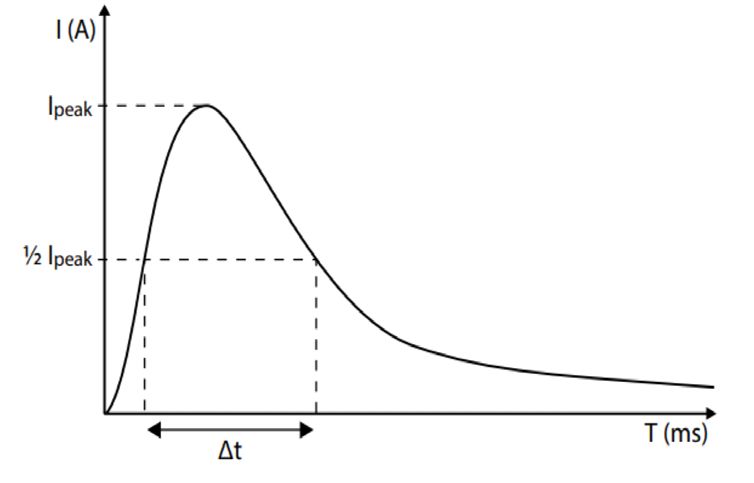
INRUSH CURRENT
This is the initial current surge drawn during product start-up. Total inrush current rises as the circuit load
increases and is one factor that can contribute to nuisance tripping of circuit breakers (MCB’s).
Practical performance will be affected by the MCB load, MCB tripping characteristics, site wiring impedance,
and the angle of the AC mainscycle at the specific moment power is applied.
Nuisance tripping issues may be improved by:
• Reducing the quantity of LED drivers connected to a single MCB.
• Re-distributing the load over multiple mains phases.
• Using an MCB with Type C (EN 60898) tripping characteristics.
• Installing additional inrush current limiting devices.
• Installing a zero crossing relay for powering up the LED drivers.
Example of a typical inrush current
graph
MCBS (MINIATURE CIRCUIT BREAKERS)
Valoya only recommend using MCB’s with “Type C” trip characteristics according to EN 60898.
The maximum quantity of Valoya products recommended for a 16A Type C MCB is stated on the product’s
technical specifications datasheet (e.g installation guide). This quantity is used as the 100% reference in the
table below. The table is provided as a tool to enable calculation of the approximate maximum load for different
MCB types and ratings. Installation wiring rating, impedances and mains switch-on angle variations may also
influence the actual practical limit.
20A branch circuit is the maximum allowed per UL certification
according to LED Drivers UL Conditions of Acceptability.
Relative Relative
MCB Rating MCB Rating
quantity quantity
TYPE (A) TYPE (A)
(%) (%)
10 37 10 62
B 16 60 C 16 100 (Ref.)
20 75 20 125
MCB example
ICL (INRUSH CURRENT LIMITER)
An ICL can help avoid nuisance MCB tripping and can be installed between the MCB
and the load. It also enables an increase the luminaire quantity up to the maximum
RMS current limit of the Inrush Current Limiter.
ICL example
14 www.valoya.com +358 10 2350 300 Version 2020.1Electrical Recommendations
RCDS (RESIDUAL CURRENT DEVICES)
An RCD is a protective safety device used to automatically disconnect
the electrical supply when an imbalance is detected between live
conductors. Requirements for use, and the needed RCD rating, will
vary depending on the type of installation. Valoya luminaires are
designed to be installed in fixed electrical installations where no plug
is permitted for connecting the luminaire to the mains supply.
SURGE PROTECTORS
Valoya LED drivers have built-in surge protection. However, to protect
against surge peaks above 4KV (e. g. Due to a lightning strike) we
recommend the installation of transient voltage surge suppression.
3-PHASE SUPPLIES
• Do not apply power without the Neutral connected.
• Ensure the supply is off before disconnecting the Neutral.
• To avoid erratic dimming or possible product damage, do not
connect the same dimmer or controller to luminaires supplied by
different mains phases.
INSULATION RESISTANCE/ ELECTRIC STRENGTH
TESTING
• Valoya products have been fully tested during manufacture.
There is no need to test again.
• If the electrical site wiring must be tested, test with the luminaires
and LED drivers disconnected from the mains supply.
• If luminaires and LED drivers are connected to the mains supply
during the test, all Live phases and Neutral must be connected
together before the test is carried out (Remember to check cor-
rect reconnection before reapplying the mains supply).
Version 2020.1 +358 10 2350 300 www.valoya.com 15Dimming Guide
DIMMING METHODS
Differences in dimming methods exist depending on the LED driver (power unit) used by the Valoya luminaire.
• 1-10V: Minimum dimmed light output is approximately 10% (Spectra dependent). The mains supply to the
driver must be switched in order to turn the light on & off.
• 0-10V: Minimum dimmed light output is approximately 6% (Spectra dependent). Below this the light out-
put is off without the need for mains switching.
DIMMING CONTROL COMPATIBILITY
Controller supply
10V (if applicable)
LED drivers used by Valoya comply with LED Driver
International standard for current sink controls; (SOURCE)
Controller
IEC 60929 Annex E. This specifies that the LED (SINK)
driver is a current source device. Compatible
controls MUST be capable of sinking the current
provided by the LED driver. Controls supplying a
10V signal ARE NOT compatible. 0V
DIMMING POSSIBILITIES BY PRODUCT RANGE
BX-Series BL-Series L-Series C-Series RX-Series
1-10V - - 0-10V 0-10V
16 www.valoya.com +358 10 2350 300 Version 2020.1Dimming Guide
DIMMING CONTROL COMPATIBILITY
Important considerations when choosing a controller
• Please check with you controller provider regarding the specification of the device.
• The number of luminaires possible to connect to a single control device will depend its specification,
specifically:
• The dimming method (1-10V or 0-10V).
• The control circuit current sink capability.
• Mains switch inrush current capacity.
• Dimming controls should only be connected to LED drivers on the same mains phase. Cross
phase connection may lead to differing control circuitry electrical potentials, reduced dimming
performance, or permanent damage to LED drivers
Due to variations in specifications, terminology and connections between different control device manufac-
turers, it is impossible to list all possible alternatives. The controller manufacturer will be able to verify that
their product is a current sink device compatible with LED drivers designed according to IEC60929 Annex E.
Examples of manufacturers of compatible control products/systems (some example products indicated).
MANUFACTURERS WEBSITE EXAMPLE PRODUCT
ABB www.abb.com 1-10 V 2112UJ-214-510
Argus www.arguscontrols.com P1A
Dinuy www.dinuy.com RE EL5 002
Ever Shining Optotech Co., Ltd www.esop-power.com EC011
Helvar www.helvar.com 140 (TK4)
Honeywell Peha www.peha.de D 430
Jung www.lutron.com Electronic potentiometer, 1-10 V
Lutron www.jung.de
Osram www.osram.com Dim MCU 1-10V
Philips www.lighting.philips.com UID8600/00 1-10V Dimmer
Priva www.priva.com
RAM www.ram-group.com
Siemens www.siemens.com 5TC8424
Version 2020.1 +358 10 2350 300 www.valoya.com 17Dimming Guide
DIMMING CONNECTION EXAMPLES
Using a simple potentiometer (1-10V / 0-10V) Luminaire
One LED driver can be connected to a standard 1 (+)
DIM +
2 (-)
DIM -
100KOhm potentiometer. Note that connection LED Driver
of multiple LED drivers to one 100KOhm poten-
tiometer is not recommended due to possibilities
for erratic dimming performance
Potentiometer
AC supply
Live (L)
Neutral (N)
Earth (E)
Using a compatible current sink 1-10V dimmer
Dimmer connections
A - Live (output)
B - Control (+) Luminaire Luminaire
C - Control (-)
D- Switched Live (Output)
LED Driver LED Driver
1 (+) 2 (-) 1 (+) 2 (-)
DIM + DIM - DIM + DIM -
A B C D
Live (L)
AC supply
Neutral (N)
Earth (E)
Using a compatible current sink 0-10V dimmer
Dimmer connections Luminaire Luminaire
A - Control (+)
B - Control (-)
LED Driver LED Driver
DIM + DIM - DIM + DIM -
A B
Live (L)
AC supply
Neutral (N)
Earth (E)
18 www.valoya.com +358 10 2350 300 Version 2020.1Care & Maintenance
CLEANING
Switch the supply OFF Allow to cool Do not use detergent
IP67 rated products.
Clean with a soft brush Wipe with soft clothes Suitable for spray cleaning with
water
BASIC FAULT FINDING
Lighting faults can be due to a rare product defect, connection error, or other external issue. Faults are unlikely
to affect both luminaire and the LED driver (power unit) together. If possible, please check if the issue is luminaire
or LED driver related. This will speed problem resolution and minimize unnecessary shipping costs.
• Switch off the mains supply.
• Disconnect the luminaire from its LED driver.
• Connect the luminaire to an unpowered, working LED driver (if available).
• Connect the mains supply to the working LED driver.
• If the problem remains, then the luminaire may be damaged.
• If the luminaire now works, then the original LED driver, or mains supply to it may be at fault.
• Note details of the problem (product type, quantity, problem description…) and contact Valoya for further
assistance.
If a problem reoccurs or affects many products at the same time, please contact Valoya (www.valoya.com/
support) for further advice and assistance.
Version 2020.1 +358 10 2350 300 www.valoya.com 19Warranty & Claims
WARRANTY
Products are covered by a limited warranty. Warranty starts from date of installation, but latest 3 months from
the delivery date.
The warranty offered is “Return-to-Base”, meaning suspected faulty items shall be returned to Valoya for fault
and warranty validation before any repair or replacement can be agreed.
Valoya warrants that each Product will be free from defects in material and workmanship for the duration of the
warranty period as long as the products are installed and used in accordance with our published specifications
and recommendations.
Warranty shall be void in the event any repairs or alterations not duly authorized by Valoya in writing are made
to the Product by any person.
CLAIMS
Before returning a suspected faulty item, please contact Valoya (www.valoya.com/support) to give details of
the issue and obtain a Return Material Authorization (RMA) reference number. Please be prepared to provide
the following information about the issue:
• Product model information (e.g. B200 NS1).
• Product serial number plus YF or XF code.
• Quantity showing problems.
• Detailed problem description.
• Photograph or video showing the issue (if possible).
• Installation / invoice date (if known).
After receiving an RMA number, Products should be suitably packed and the package or shipping paperwork
clearly marked with the RMA number. Returns received without an RMA reference number may be rejected.
Valoya will inspect the returned items to validate fault and warranty validity. If Valoya determines to its satisfaction
that warranty is valid, Valoya will repair or replace the Product with one of similar age. Where a warranty claim
is justified, Valoya will pay for the return freight expenses for repaired or replaced items. Valoya reserve the
right to invoice for returning Products that are not found to be defective, or do not comply with the terms of this
warranty, together with associated freight, testing and handling costs.
* Above is a summary of our warranty and claim policy. For full details please see: www.valoya.com/
warranty.
20 www.valoya.com +358 10 2350 300 Version 2020.1Standards / Contact
Standards applied (where applicable):
EUROPE
EN60598-1: Luminaires. General requirements and tests.
EN60598-2-1: Luminaires. Part 2: Particular requirements. Section one – Fixed general purpose luminaires.
EN62031: LED modules for general lighting. Safety specifications.
EN 62493: Assessment of lighting equipment related to human exposure to electromagnetic fields.
EN55015: Limits and methods of measurement of radio disturbance characteristics of electrical lighting and similar equipment.
EN61547: Equipment for general lighting purposes. EMC immunity requirements.
EN61000-3-2: Electromagnetic compatibility - Limits - Limits for harmonic current emissions.
EN61000-3-3: Electromagnetic compatibility – Limits - Limits for Voltage Fluctuations and Flicker.
IEC EN 61000-4-2: Electromagnetic compatibility (EMC)- Part 4-2: Testing and measurement techniques - electrostatic discharge immunity
test.
IEC EN 61000-4-3: Electromagnetic compatibility (EMC)- Part 4-3: Testing and measurement techniques - radiated, radio-frequency,
electromagnetic field immunity test.
IEC EN 61000-4-4: Electromagnetic compatibility (EMC) - Part 4-4: Testing and measurement techniques - Electrical fast transient/burst
immunity test.
IEC EN 61000-4-5: Electromagnetic compatibility (EMC) - Part 4-5: Testing and measurement techniques - Surge immunity test.
IEC EN 61000-4-6: Electromagnetic compatibility (EMC) - Part 4-6: Testing and measurement techniques - Immunity to conducted
disturbances, induced by radio-frequency fields.
IEC EN 61000-4-8: Electromagnetic compatibility (EMC) - Part 4-8: Testing and measurement techniques - Power frequency magnetic field
immunity test.
IEC EN 61000-4-11: Electromagnetic compatibility (EMC) - Part 4-11: Testing and measurement techniques - Voltage dips, short
interruptions and voltage variations immunity tests.
IEC 61347-2-13: Lamp controlgear. Particular requirements for d.c. or a.c. supplied electronic controlgear for LED modules.
IEC 61347-1: Lamp controlgear - Part 1: General and safety requirements.
IEC 62384: DC or AC supplied electronic control gear for LED modules. Performance requirements.
EN62471: Photobiological safety of lamps and lamp systems.
EN62560: Self-ballasted LED-lamps for general lighting services by voltage >50V - Safety specifications.
EN62776: Double-capped LED lamps designed to retrofit linear fluorescent lamps - Safety specifications.
NORTH AMERICA
UL1598: Luminare safety.
UL8750: Light Emitting Diode (LED) equipment for use In lighting products.
UL2108: Standard for Low Voltage Lighting Systems.
UL 8800: Outline of Investigation for Horticultural Lighting Equipment
CSA C22.2: #9.0: General Requirements for Luminaires.
CSA C22.2: #250.0.8: Safety for Light emitting diode (LED) equipment for lighting applications.
CSA C22.2 No. 250.13-14: Light Emitting Diode (LED) equipment for use in lighting products.
Contact: Distributor list can be found at:
www.valoya.com/contact
Melkonkatu 26,
00210 Helsinki,
Finland
T +358 10 2350 300
E sales@valoya.com
W www.valoya.com
Valoya® is a registered trademark of Valoya Oy in the European Community, the USA and certain other countries.
Due to our continuous program of product development, data is subject to change without notice.
Version 2020.1 +358 10 2350 300 www.valoya.com 21You can also read