Integrating motion capture in a virtual reality intervention planning platform to study radiation protection measures for the ATLAS inner detector ...
←
→
Page content transcription
If your browser does not render page correctly, please read the page content below
Journal of Instrumentation

PAPER • OPEN ACCESS

Integrating motion capture in a virtual reality intervention planning
platform to study radiation protection measures for the ATLAS inner
detector decommissioning
To cite this article: A. Cryer et al 2021 JINST 16 P03020

View the article online for updates and enhancements.

 This content was downloaded from IP address 128.141.192.28 on 18/03/2021 at 09:06
Published by IOP Publishing for Sissa Medialab
 Received: October 23, 2020
 Revised: January 19, 2021
 Accepted: January 19, 2021
 Published: March 12, 2021

 2021 JINST 16 P03020
Integrating motion capture in a virtual reality intervention
planning platform to study radiation protection measures
for the ATLAS inner detector decommissioning

A. Cryer, ,∗ G. Kapellmann-Zafra, H. Marin-Reyes, K. Lohwasser, A. Steel, K. Veale
and M. Jaekel
 University of Sheffield, Sheffield, S10 2TN, U.K.
 CERN, Geneva, Switzerland

 E-mail: a.cryer@sheffield.ac.uk

Abstract: An intervention planning and evaluation platform has been developed to enable dose
estimation and personnel training for the ATLAS inner detector decommissioning. The present
paper describes the integration of motion capture into the system, including the dose estimation
results for the recorded decommissioning steps.

Keywords: Dosimetry concepts and apparatus; Models and simulations; Radiation calculations;
Simulation methods and programs

 ∗ Corresponding author.

 c 2021 CERN. Published by IOP Publishing Ltd on behalf of Sissa
 Medialab. Original content from this work may be used under the terms
of the Creative Commons Attribution 4.0 licence. Any further distribution of this work https://doi.org/10.1088/1748-0221/16/03/P03020
must maintain attribution to the author(s) and the title of the work, journal citation
and DOI.
Contents

1 Introduction 1

2 Related work 2

3 Overview of the system 2
 3.1 Advantages of using virtual reality for training 3

 2021 JINST 16 P03020
 3.2 Proof of concept 4

4 Experimental setup 4
 4.1 ATLAS ID decommissioning steps to be recorded 4
 4.2 Motion capture setup 4
 4.3 Motion capture data processing 5
 4.4 Virtual reality implementation 7

5 Results and discussion 8

6 Conclusion 10

1 Introduction

Upgrades to the ATLAS detector required for the High Luminosity Large Hadron Collider (HL-
LHC) are scheduled to take place during CERN’s next Long Shutdown (LS3), 2025. This includes
the replacement of the ATLAS Inner Detector (ID) by the Inner Tracker (ITk). It will require
significant manpower over several months for a complete removal of both the ID and its associated
services. The ATLAS ID has been exposed to intense high energy particle beams for several years,
creating a challenging radiation environment for personnel [1]. Observing the “as low as reasonable
achievable", ALARA principle [2] in radiation protection requires careful planning of all human
interventions. Reliable feedback is needed to get an accurate dose estimate for optimising the work
however, familiarisation of the situation in-situ is limited without entering the irradiated area.
 In order to address these issues, an intervention planning and evaluation platform was designed
to double as a tool for dose estimation and training for personnel. This paper presents the addition of
motion capture (MoCap) in the development of the platform, including the dose estimation results
for a subset of anticipated work.
 There are some key advantages to assessing and training for high-risk interventions using this
virtual reality (VR) platform, however there are drawbacks to a wholly VR system. These centre
around the lack of effort expended to interact with the virtual environment while using the HTC
Vive headset and hand controllers. Intervention planning and dose estimation relies firstly on an
accurate map of the radiation in the environment, and secondly on accurate simulation of where

 –1–
the worker will move, and how long they will spend at each point. Previous dose estimations were
carried out using a spreadsheet, listing the position of people with approximate distance from the
activated material. The result was often an over-estimation of the dose by a factor of 2 to 4 compared
to the actual received dose recorded by the personal dosimeter, as this method did not take into
account the actual movement of a person and precise timing. In order to anticipate and adapt to
higher dose levels in future decommissioning scenarios, the accuracy of the dose estimation needed
to be improved.
 Furthermore, effortless motions could introduce errors in timing estimations for task completion
and thus reduce the accuracy of the dose estimation. The use of MoCap to obtain external location
data was introduced to address these concerns and improve dose estimations. Motion capture

 2021 JINST 16 P03020
was used to track real-life movements of a technician performing the decommissioning steps on a
purpose built mock-up. This provided accurate location and timing data for each of the tasks, ready
to then be imported into the Virtual Reality Intervention Planning Platform.

2 Related work

Using Virtual Reality to train for high exposure procedures has been investigated as early at 2003,
by the CIPRES (Calculós Interactivos de Protección Radiológica en Entorno Simulado) project [3].
 Networked VR headsets navigating a shared environment was a key aspect of a platform
developed to train workers in the case of nuclear industrial accidents in 2016 [4]. Research into
virtual reality applications in the nuclear sector has put emphasis on the immersive experience that
VR headsets give to the user [5].
 The combination of motion capture and virtual reality has been explored in fusion reactor
assembly [6].
 Mapping radiation in 3D for VR decommissioning training has also been developed as a
response to the Fukushima disaster [7].
 CERN itself has used virtual environments for planning and design since the 1990s, with its
VENUS project (Virtual Environment Navigation in the Underground Sites) [8], and it has ongoing
research using Augmented Reality for the collimator exchange process [9], and AR with robotics
inside the Collider tunnel [10].

3 Overview of the system

The Virtual Reality Intervention Planning Platform has two complementary parts. Firstly, it is an
intervention planning platform that tracks the radiation dose of animated avatars, and secondly, its
is a personnel training platform that uses VR headsets to immerse trainees in the environment with
minimal risk.
 The Virtalis Visionary Render [11] was used as the development platform. It is a 3D-model
viewing software with a basic physics engine. The software can restrict users and objects to the
laws of classical mechanics. It also has a networking function to allow multiple users to connect to
a master copy and interact within the same virtual environment simultaneously.
 The Visionary Render software creates a 3D space which can then be populated with CAD
models. However, there is a limited capability to modify the CAD objects inside the software, as

 –2–

well as create basic geometric volumes. Certain properties of these CAD assemblies can be altered
to the user’s specifications, such as the colour, visibility, mobility, and solidity of an object (where
the object can be always solid and always causes collisions, or collides only with other specified
objects, or is completely intangible). Collision-enabled objects are useful to determine logistics of
an intervention. If moving an object is more complicated than first anticipated e.g. it is too long and
will get stuck around a corner, it is better to discover this inside an accurate simulated environment,
rather than in the field while workers’ doses accumulate. Conversely, scripts can be triggered by
entering a delimited area — which is only possible if the object marking the volume boundary is
intangible.

 2021 JINST 16 P03020
 The radiation data is contained in an external csv file. In this work, the radiation maps were
made by CERN RP using FLUKA simulations. FLUKA is a particle transport code to simulate
nuclear and sub-nuclear particle interactions through complex geometries [12]. When the VR scene
is opened, the first recorded map is loaded. During run-time, other maps can be loaded and swapped
to the scenario. A change of radiation map can be triggered by any single or combination of events,
such as a timers or objects being moved.
 The training side of the system was conceived and designed to give users the maximum amount
of agency while in the environment. Workers get a realistic experience and can practise jobs without
physical consequences; supervisors can oversee the expected radiation doses for each intervention.
This is especially useful when planning one-time interventions where there is a significant dose
risk, and no previous similar circumstance to exploit.
 HTC Vive headsets are used with the Steam VR interface to immerse the users inside the
environment. The headset can track the user around an unobstructed physical area using two base-
station towers that scan in infrared. For movements that would be too large for natural movement
inside the delimited area, the HTC Vive hand controllers can translate or teleport the user inside
the virtual world, as well as interact with virtual objects.

3.1 Advantages of using virtual reality for training

Virtual Reality removes many of the constraints around the exploration of harsh environments by
providing an accurate facsimile of the situation without the associated risks [13]. It also opens
a whole new perspective on the ‘learn-by-doing’ approach to teaching. There is no exposure to
radiation while using immersive technologies, as opposed to traditional ‘on the ground’ methods
of demonstration. The system also allows multiple workers to interact with and within a shared
environment.
 The environment can be explored at will, leaving users to assess the feasibility and dose-cost of
a planned intervention, as well as allow a supervisor or radiation protection officer to demonstrate
to their trainees or students what work needs carrying out, and how to accomplish it. This system
can be translated into any situation requiring human presence in a radioactive environment. It can
be used as a tool to teach protocols for different working scenarios; including routine tasks such
as nuclear reactor refuelling, general maintenance for particle accelerators (medical and research),
fusion reactors, hazardous waste handling in construction and decommissioning of power stations,
oil rings, factories and buildings; as well as scenarios such as disaster prevention training or
post-disaster exploration. It could also be adapted for space applications.

 –3–
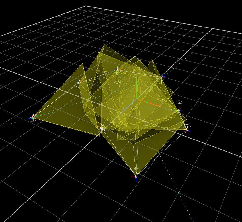
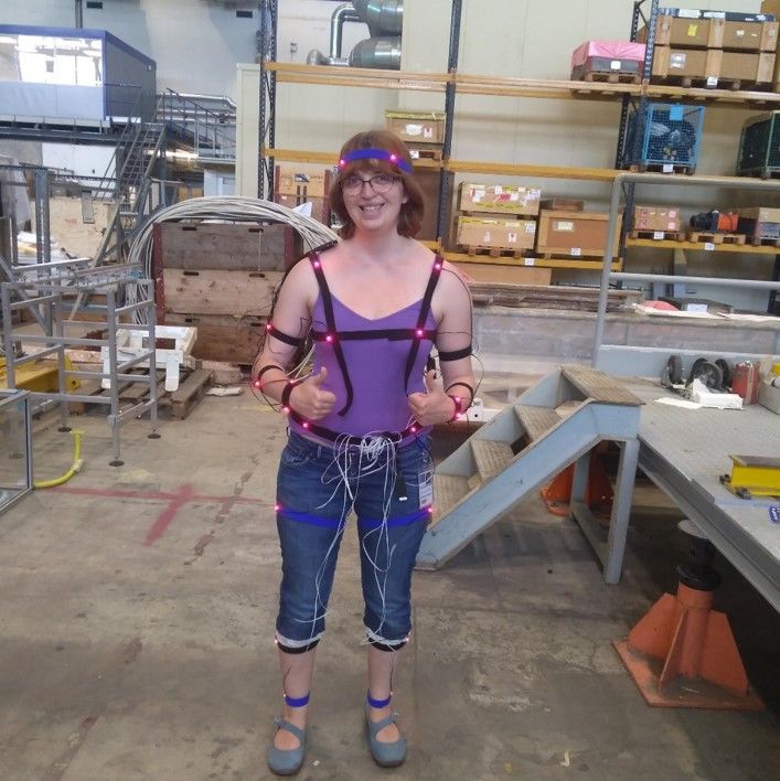
3.2 Proof of concept
A proof of concept for the platform was performed using the Birmingham cyclotron vault [14].
The vault was rendered in a virtual world, and its background radiation mapped for the system.
The virtual dosimeter calculations used the rectangle rule of integration computation. Six easily
identifiable points inside the radiation area were chosen, and a path around the space incorporating
these points was plotted. A person stood at each point for 30 seconds and measured the immediate
dose. After the 6th point, their total radiation dose was noted. The radiation dose of the path
was recorded as 2.9 ± 0.3 μSv using the average of multiple measurements. The same route was
followed in the virtual environment using the HTC Vive headset. With guidance checkpoints and

 2021 JINST 16 P03020
dosimeter visible, the mean radiation dose was 2.6 ± 0.2 μSv.
 This proof of concept showed the VR platform returned a comparable result to the real radiation
exposure for a predefined route through the vault, well within the accuracy of standard dosimeters
(±20%). The errors of the system were found to be dependent on the accuracy of the dose map used,
and the user following the same established route. With an accurate dose map and reliable location
data, the system will produce reliable results. The conclusion drawn from the study determined that
the accuracy of the virtual dosimeter depended on the accuracy of the dose maps.

4 Experimental setup

4.1 ATLAS ID decommissioning steps to be recorded
The planned total duration of the ATLAS ID decommissioning is six months. It was therefore not
feasible to attempt motion capture of the whole process. Instead, the removal of the beampipe, and
preparation for the Pixel Detector extraction were recorded. These sections of work were prioritised
for their location close to the relatively radiation ’hot’ beampipe, and can be performed on an
accurate existent model of the CERN ATLAS Inner Detector, also referred to as the ATLAS ID
Mockup.
 The ATLAS ID Mockup exists physically at CERN in Geneva in a surface building. It was
created to train for the installation and assess wiring for the Pixel Detector Inner Layer (IBL), and
was updated and reused for the Motion Capture work for the ATLAS ID decommissioning presented
in this paper.

4.2 Motion capture setup
The motion capture system used was a commercial solution called PhaseSpace [15]. The setup
comprised of eight stereo cameras set up at varying heights in an approximate circle, and forty
LEDs. The LEDs pulse at individual frequencies allowing the system to track each of them
independently. The system requires line-of-sight, however the target area included the scaffolding
around the Mockup ID end-plate. This was not ideal; the extrapolation of location was possible,
albeit with some occlusions. An occlusion is an obstruction preventing line-of-sight between the
LED and the cameras. This in turn prevents the system from successfully calculating the LED’s 3D
location.
 Figure 1 shows the placement of LEDs on the body. Velcro strips were used to attach the
LEDs to the body. Using LEDs sewn to Velcro had several advantages: it made the setup flexible,

 –4–
2021 JINST 16 P03020
 (b) One of the authors wearing the LEDs to calibrate the
 system and test for occlusions. Velcro strips were used to
 (a) The placement of LEDs on the body attach the LEDs to the body.

Figure 1. LED placement was determined through trial-and-error to determine the best setup with the least
obtrusive occlusions.

simplifying the trial of different LED positions; it kept the LEDs close to the body, whereas LEDs
attached to baggy clothing deformed the capture result; and made it easier to wear. Adhesive tapes
on clothing had been used in the beginning, however Velcro proved more durable, less wasteful,
and gave a more consistently reliable result. The optimal setup of the cameras and LEDs for best
coverage was determined through trial and error, however occlusions could not be totally avoided.
 Figure 2 shows the position of the stereo cameras. The software calculates their whereabouts in
space from an initial calibration using LEDs set in a baton. The yellow pyramids show the cameras
field of vision.

4.3 Motion capture data processing

After the motions were recorded by the cameras, the data was then processed, initially to move from
disassociated individual moving points, to a human skeleton with its associated form. This was
achieved using PhaseSpace’s associated software Recap2. The skeleton data was then imported and
further processed in Autodesk MotionBuilder [16].
 Occlusions obstruct the camera’s view of the LEDs, so the system could not locate their point
in space. The longer the LEDs were occluded, the more their location data deteriorates. This led to
many unpredictable un-physical effects to the character’s movement and had to be ’cleaned’ from
the raw data.
 The data was cleaned firstly by creating ’rigid bodies’. Rigid bodies work by grouping LEDs
together and imposing that they should not move relative to one another. Rigid bodies are useful
in the case of an occlusion, as the system is able to extrapolate where the missing LED can be
found, despite not being able to see it. Rigid bodies were most effective defining a cross section
of the body, for example: grouping the four hip LEDs, or the four head LEDs together. As these

 –5–
2021 JINST 16 P03020
Figure 2. The position of the stereo cameras shown in PhaseSpace Master software, single white squares
are 1m2 .

are defined by the size of the cranium and the pelvis, it can be assumed these LEDs will not move
relative to each other. Defining a rigid body over the front chest area was less effective, as when the
technician crouched or stretched, these LEDs would move relative to one another. Since this went
against the principles of the rigid body, the extrapolation of the missing LED’s position was less
successful.
 Secondly, an actor and a character skin were added to the skeleton. An actor adds volume to the
skeleton using body segments. These are mapped to the relevant LEDs, and will rotate with these
LEDs and the skeleton as they move in time. A character skin was then applied on top. Figure 3
shows the actor and character skin being added to the skeleton. The character skin is not only
cosmetic, it also makes sure the actor segments do not detach from the whole. This occurrence was
particularly common if there was an occlusion of a significant joint LED such as the shoulder.
 Not all LEDs are given equal importance by the system. Some, such as the feet, have a greater
bearing on the avatar’s pose and position than others. An occluded foot LED could be the deciding
factor determining the avatar’s location in virtual reality, despite contradicting information from all
the other LEDs. Although the previous steps succeeded in addressing most of the issues, problems
such as these had to be corrected individually, case-by-case.

 –6–
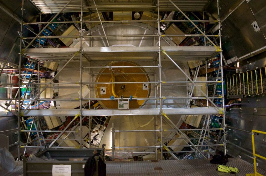
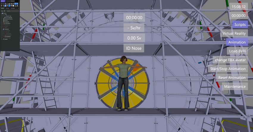
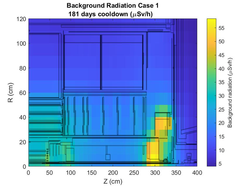
2021 JINST 16 P03020
(a) The “actor" is aligned with the motion capture points in (b) The “character skin" is added to the actor in Autodesk
Autodesk MotionBuilder MotionBuilder

Figure 3. Autodesk MotionBuilder was used to process the data, moving from an animated skeleton to a
character.

 Finally this clean processed data — character model, skeleton and animation, was imported into
the Intervention Dose Estimation platform in Virtalis Visionary Render as an filmbox (.FBX) file.

4.4 Virtual reality implementation

The data imported in the FBX file is then added to an animation sequence in Virtalis. This sequence
links all the imported animations, with added effects on the virtual environment.
 This allows the worker’s movements to be put in context, with the environment responding to
the simulated actions (e.g. parts of the detector are added/removed, or the dose map is changed). The
two dose maps used for the work carried out for the ATLAS Experiment were provided by CERN’s
Radiation Protection team, have a resolution of 10 cm2 and are a result of extensive simulations
of LHC operations [1]. The validity of these dose maps were tested by direct measurements of
the radiation levels during the ongoing shutdown LS2. Where needed the FLUKA model was
improved. Measured and calculated values agreed within ≤ 20% in all relevant areas. A subsection
of one of the dose maps used in this work can be seen in figure 4. The first dose map (Case 1) is
with the beam-pipe and the IBL subsections installed. The second dose map (Case 2) is with the
beam pipe and the IBL removed, but the rest of the Pixel Detector still in place.
 It was decided to focus on simulating the dosimeter readings of the technician’s interventions
with the dosimeter resting the technician’s chest. Certain decommissioning steps will be repeated.
Rather than record the same process multiple times, instead the simulation multiplies the dose added
to the dosimeter at the end of the required section of work, as needed.
 Figure 5 shows the scaffolding around the ATLAS Endplate, and its the Digital Twin inside
the Intervention Planning Platform, while figure 6 shows the different stages of data gathering and
processing from the Motion Capture setup to the Intervention Planning Platform.

 –7–
2021 JINST 16 P03020
Figure 4. Map of the background radiation in the ATLAS cavern after 181 days cooling time, zooming in
on the ATLAS ID with the detector geometry overlaid, based on [1]. The origin is the collision point. The
dose map shows a quadrant of the detector, as it is symmetric along the Z and R axes. The radiation dose is
the average over all the points of .

5 Results and discussion

The result of the simulation showed that the decommissioning steps performed would take 3 hours
7 min and the technician would accrue 13.47 Sv radiation dose, see table 1. To put in context, the
radiation restrictions for occupational exposure for both France and Switzerland is 20 mSv/year [17].
CERN itself aims for worker exposure below 3 mSv/year [18], which is approximately an individual’s
annual background exposure.
 The technician who carried out the decommissioning steps for the motion capture, shown in the
top left of figure 6, was involved with the original ID installation and was familiar with the expected
decommissioning tasks. He is also anticipated to carry out the real ID decommissioning during
the LS3 shutdown. While during the real decommissioning, he will be wearing the appropriate
PPE as expected for ATLAS work. These will be a helmet, safety shoes and operational dosimeter.
A self-rescue mask will be placed nearby, but not worn. However in this work concessions were
made for the motion capture data processing algorithms, which returned the best results when the
LEDs had body contact. The effect of the extra PPE on the technician’s movements is considered
negligible.
 Due to time constraints, the data recording was undertaken just once so far, but can be repeated
when needed. While the training aspect of the platform was not utilised in this work, the estimation

 –8–
2021 JINST 16 P03020
 (a) The real scaffolding around the ID Endplate in the ATLAS underground cavern

 (b) A virtual avatar on the scaffolding around the ID Endplate in the VR Intervention Planning
 Platform

 Figure 5. The ATLAS detector and its Digital Twin inside the Intervention Planning Platform.

provides a baseline result for an experienced technician familiar with the tasks, and can be used as
a reference for training.
 The technician worked without any restriction on where he stood and no direct knowledge of
the dose accumulation as he worked. It was noted that the technician spent a significant amount of
time in front of the beam pipe — the most radioactive section of the detector. By carefully analysing
the data collected in this work, it is now possible to minimise the received dose by adjusting the
location and posture of each technician. In a next step, various shielding concepts can be analysed by
updating the corresponding radiation maps and directly compare the effectiveness of the shielding
on the estimated dose. This will become more important in future HL-LHC shutdowns due to the
significantly higher radiation doses.

 –9–
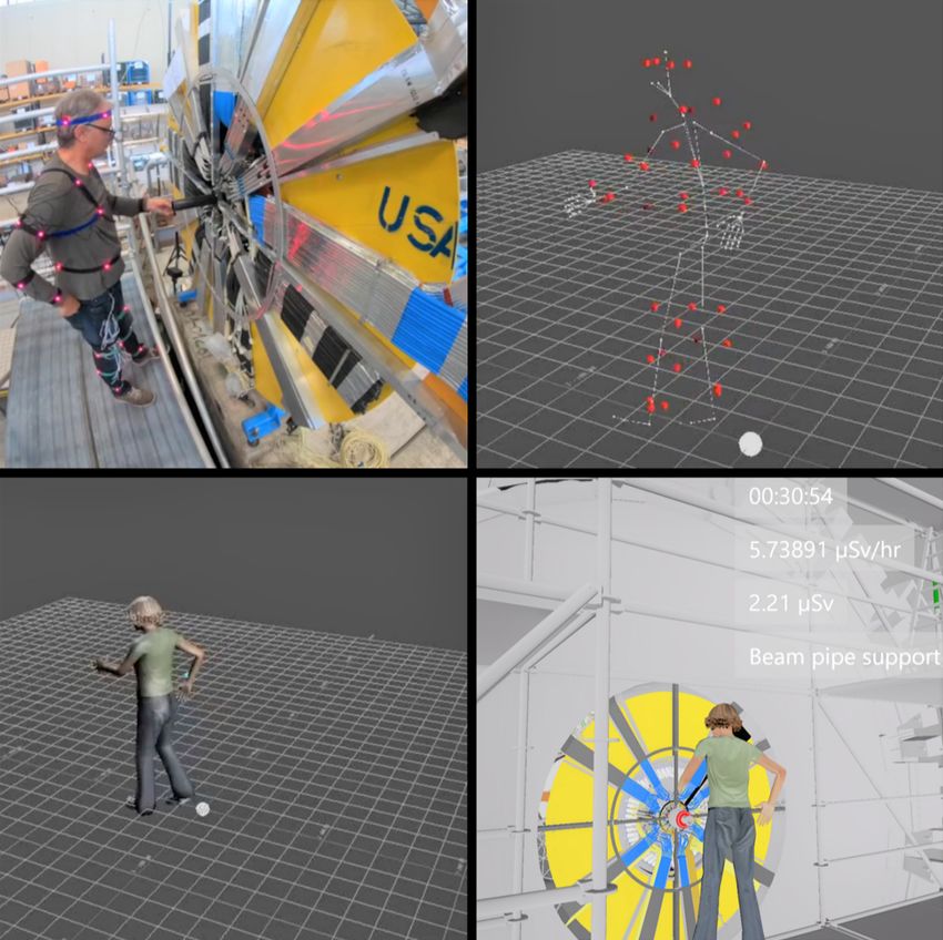
2021 JINST 16 P03020
Figure 6. Top left: Technician performing decommissioning step with LEDs for Motion Capture; Top right:
the MoCap data with Skeleton in PhaseSpace; Bottom left: The MoCap data with actor in MotionBuilder;
Bottom right: The MoCap data in the Intervention Planning Platform.

Table 1. Results of the Motion Capture dose estimation. Summing the individual parts of the work leads to
an estimated 13.50 μSv, this caused by rounding the results of each section.

 Objective Steps Duration hh:mm:ss.ff Dose Estimate Sv
 Remove inner IDEP Nose
 Remove IDEP 25:44.52 1.95
 Remove outer IDEP Nose
 Clear BeamPipe/IBL support Remove rad monitor quarter circles, BP support beams, and BP sliding ring 6:49.33 0.57
 structures Remove outer quarter ring 3:02.00 0.22
 Cut IBL services and Remove IBL service guide 9:18.33 0.61
 Remove heater trays and tubing 42:36.60 2.89
 Clear IBL and pixel services Cut ER bundle 2:48.96 0.21
 Cutting internal Pixel services 1:08:40.72 5.23
 Remove PST seal plate 8:56.64 0.67
 Install PST rail interface 3:23.64 0.27
 Prepare Pixel for extraction Install pixel support ring 9:51.19 0.60
 Install internal transition rails 1:07.73 0.06
 Install intermediate rail and frogs 4:20.65 0.22
 Total 3:06:47.61 13.47

6 Conclusion

An intervention planning and evaluation platform was created to evaluate expected dose exposure
rates during the ATLAS ID decommissioning. Motion capture was used to record the movements
of a technician performing decommissioning tasks on the ATLAS ID Mockup. The addition

 – 10 –
of motion capture was motivated by the main drawback to VR-based training and simulation
platforms, where work carried out in VR has no effort, skewing the dose estimate as tasks are
easier and faster to accomplish. The motion capture records the technician’s movements while
performing decommissioning tasks in real-time on the mockup, meaning that the location and
timing in completing the tasks is accurate.
 The platform provided important information for the dose estimation for the ATLAS ID
decommissioning. The expected time-frame for removal was revised down, due to the speed
at which the technician carried out the work. The platform calculated the dose estimation as parts
of the detector are programmed to (dis)appear as the decommissioning simulation runs. The total

 2021 JINST 16 P03020
work duration was 3 hours 7 minutes, and the radiation dose exposure estimate was 13.47 μSv for
this first part of the decommissioning. The later steps will be performed in a significantly reduced
radiation field, as the most activated parts (the beam pipe and the Pixel Detector) will have been
removed. The analysis of these later steps is still ongoing and will add to the total received dose of
the personnel.
 The motion capture complements the hands-on training aspect of the platform, which uses VR
headsets. The two uses of the system balance each other — the motion capture gives the more
accurate result, however immersion and interactivity are more important when the platform is used
for training. Peaks in the dose rate can be assessed, and improvements to the predicted exposure
can be demonstrated, such as targeted shielding, or by physically avoiding certain high-risk areas.
 Improvements to the system such as the development of dynamic dose maps have been proposed
which would allow for a gradual movement of parts of the detector instead of an instantaneous
removal by switching between static dose maps as implemented currently. This would make the
platform more flexible in its possible applications.
 The development of a Digital Twin to the platform has been proposed. The addition would
allow training for cooperative human-robot interventions. Provided the Digital Twin could interact
and alter the VR environment, the setup would also provide an extra point of view to oversee
the robot’s execution of tasks — beyond camera and sensor feedback. Adding to this, once the
radiation tolerance of the robotic components is known, malfunctions or mechanical failures can be
anticipated and repairs planned — including ordering spare components in advance, which reduces
down time.

Acknowledgments

The authors would like to thank Valery Akhnazarov for performing the decommissioning steps for
the motion capture, as well as Richard French and Samantha Abrego from the ESIM group for their
support throughout the project. Robert Fröschel and Juan Carlos Armenteros Carmona from CERN
RP for their work on the FLUKA model and providing the radiation dose maps used in this work.
 This work was funded by: The European Union’s Horizon 2020 Research and Innovation
programme under Grant Agreement no. 654168. Uk-ITk Irradiation Programme Grant No.
4070170493. STFC Innovation Placement Grant No. 4070215728. EPSRC ECR Capital En-
hancement Programme, and EPSRC Studentship 1957171.

 – 11 –
References

 [1] J.C. Armenteros, A. Cimmino, S. Roesler and H. Vincke, FLUKA Studies of Dose Rates in the ATLAS
 Standard Opening Scenario, in 13th International Topical Meeting on Nuclear Application of
 Accelerators (AccApp’17), Quebec City Canada (2017), pg. 62.
 [2] ICRP, Recommendations of the International Commission on Radiological Protection, ICRP
 Publication 9, Pergamon Press, Oxford U.K. (1966).
 [3] J. Rodenas, I. Zarza, M. Burgos, A. Felipe and M.L. Sánchez-Mayoral, Developing a virtual reality
 application for training nuclear power plant operators: Setting up a database containing dose rates
 in the refuelling plant, Radiat. Protect. Dosim. 111 (2004) 173.

 2021 JINST 16 P03020
 [4] K. Seong Jeong et al., The safety assessment system based on virtual networked environment for
 evaluation on the hazards from human errors during decommissioning of nuclear facilities, Reliab.
 Eng. Syst. Saf. 156 (2016) 34.
 [5] M. Henrique da Silva, A. Paula Legey and A.C. de A. Mól, Review study of virtual reality techniques
 used at nuclear issues with emphasis on Brazilian research, Ann. Nucl. Energy 87 (2016) 192.
 [6] L. Meunier, D. Keller and P. Guédon, Virtual Reality: Lessons learned from WEST design and
 perspectives for nuclear environment, Fusion Eng. Des. 136 (2018) 1337.
 [7] Y. Sato, K. Minemoto, M. Nemoto and T. Torii, Construction of virtual reality system for radiation
 working environment reproduced by gamma-ray imagers combined with SLAM technologies, Nucl.
 Instrum. Meth. A 976 (2020) 164286.
 [8] J.-F. Balaguer and S. de Gennaro, VENUS: A Virtual Reality Project at CERN, SIGGRAPH Comput.
 Graph. 30 (1996) 40.
 [9] H. Martínez, T. Fabry, S. Laukkanen, J. Mattila and L. Tabourot, Augmented reality aiding collimator
 exchange at the LHC, Nucl. Instrum. Meth. A 763 (2014) 354.
[10] L. Angrisani, P. Arpaia, D. Gatti, A. Masi and M. Di Castro, Augmented Reality monitoring of
 robot-assisted intervention in harsh environments at CERN, J. Phys. Conf. Ser. 1065 (2018) 172008.
[11] Virtalis, Visionary Render (2019.2), https://www.virtalis.com (2019).
[12] A. Fasso, M. Silari and L. Ulrici, Predicting induced radioactivity at high-energy electron
 accelerators, J. Nucl. Sci. Tech. 37 (2000) 827.
[13] A. Cryer, G. Kapellmann-Zafra, S. Abrego-Hernández, H. Marin-Reyes and R. French, Advantages of
 Virtual Reality in the Teaching and Training of Radiation Protection during Interventions in Harsh
 Environments, in 24th IEEE International Conference on Emerging Technologies and Factory
 Automation (ETFA), Zaragoza Spain (2019), pg. 784.
[14] A. Cryer, G. Kapellmann-Zafra, S. Abrego-Hernández, H. Marin-Reyes and R. French, Proof of
 Concept for a Virtual Reality Intervention Evaluation and Training Platform for Highly Radioactive
 Environments, in Proceedings of the 27th International Nuclear Physics Conference, Glasgow U.K.
 (2019).
[15] PhaseSpace, PhaseSpace, https://phasespace.com (2019).
[16] Autodesk, Autodesk MotionBuilder, https://autodesk.com/products/motionbuilder (2019).
[17] EURATOM, 2013/59/EURATOM, Council Directive (2013).
[18] D. Forkel-Wirth et al., , in Proceedings of LHC Performance Workshop (Chamonix 2014), Chamonix
 France (2014), pg. 276.

 – 12 –
You can also read