INTELLIZONE COMMERCIAL OZONE GENERATOR - Models CD-250F, CD-400F, CD-800F and CD-1200F - Pentair
←
→
Page content transcription
If your browser does not render page correctly, please read the page content below
1

INTELLIZONE                   ™

COMMERCIAL OZONE GENERATOR
Models CD-250F, CD-400F, CD-800F and CD-1200F

                                                INTELLIZONE
                                                                                TM

                                                COMMERCIAL OZONE SYSTEM
                                                ADVANCED SANITATION SOLUTIONS

                                                                   INSTALLATION AND
                                                                       USER'S GUIDE

                 IMPORTANT SAFETY INSTRUCTIONS
                READ AND FOLLOW ALL INSTRUCTIONS
                    SAVE THESE INSTRUCTIONS
                                  INTELLIZONE™ COMMERCIAL OZONE GENERATOR Installation and User's Guide
2
Table of Contents
SECTION 1. General Information...................................................................................................... 1
Ozone Application.....................................................................................................................................................1
Ozone Generator Overview...................................................................................................................................1
Warranty Summary...................................................................................................................................................1
SECTION 2. Installation. ................................................................................................................... 3
System Overview.......................................................................................................................................................3
Unpacking and Inspection.....................................................................................................................................3
Location.........................................................................................................................................................................3
Transportation............................................................................................................................................................3
Mounting......................................................................................................................................................................3
Connections.................................................................................................................................................................3
User I/O Panel..............................................................................................................................................................4
Pre-Commissioning Checklist...............................................................................................................................7
SECTION 3. Commissioning............................................................................................................. 7
Ozone Generator Check..........................................................................................................................................7
Support Systems Check...........................................................................................................................................7
Initial Start-Up.............................................................................................................................................................7
Supply Voltage Check...............................................................................................................................................8
Vacuum Regulator Check........................................................................................................................................8
External Control Check............................................................................................................................................8
Ready for Normal Operation..................................................................................................................................8
SECTION 4. Operation . ................................................................................................................... 8
System Overview.......................................................................................................................................................8
System Power Up.................................................................................................................................................... 11
System States........................................................................................................................................................... 11
SECTION 5. Maintenance & Service. ..............................................................................................13
Preventative Maintenance Schedule............................................................................................................... 13
Electrode and Ground Tube Cleaning – Module in Place ....................................................................... 13
Ozone and Module Inspection and Service.................................................................................................. 14
Air Filter Cleaning................................................................................................................................................... 16
Oxygen Filter Cleaning......................................................................................................................................... 17
Replacement Parts and Order Information................................................................................................... 18
Standard Replacement Parts List...................................................................................................................... 18
INTELLIZONE™ COMMERCIAL OZONE GENERATOR Installation and User's Guide3
Table of Contents
SECTION 6. Troubleshooting..........................................................................................................19
System will not start.............................................................................................................................................. 19
Low Ozone Output................................................................................................................................................. 19
Module Current Does Not Correspond to Power Setting........................................................................ 19
Fault Message: BFPD.............................................................................................................................................. 19
Fault Message: LOW O2 PRESSURE................................................................................................................... 20
Fault Message: LOW O2 %................................................................................................................................... 20
Fault Message: COOLANT TEMP........................................................................................................................ 20
Fault Message: LOW COOLANT FLOW............................................................................................................. 20
Fault Message: AMBIENT AIR TEMP.................................................................................................................. 20
Fault Message: TRANSFORMER TEMP.............................................................................................................. 21
Fault Message: LOW VACUUM............................................................................................................................ 21
Fault Message: HIGH VACUUM........................................................................................................................... 21
Fault Message: PROCESS FLOW......................................................................................................................... 21
Fault Message: AMBIENT OZONE...................................................................................................................... 22
Fault Message: 4-20mA SIGNAL LOSS............................................................................................................. 22
Fault Message: INVERTER..................................................................................................................................... 22
Fault Message: PHASE LOSS................................................................................................................................ 22
System Pauses.......................................................................................................................................................... 23
SECTION 7. Warranty. ....................................................................................................................24
APPENDIX......................................................................................................................................25
APPENDIX A: OUTPUT CURVES.......................................................................................................................... 26
APPENDIX B: SPECIFICATIONS............................................................................................................................ 27
APPENDIX C: PRE-COMMISSIONING CHECKLIST......................................................................................... 28
APPENDIX D: OZONE PROCESS SYSTEM LAYOUT........................................................................................ 29
APPENDIX E: SYSTEM/CONTROLS BLOCK DIAGRAM.................................................................................. 30
APPENDIX F: WIRING DIAGRAM......................................................................................................................... 31
APPENDIX G: PLC FUNCTIONAL SPECIFICATION......................................................................................... 33
APPENDIX H: MAINTENANCE LOG SHEET...................................................................................................... 47
APPENDIX I: PRESSURE CONVERSION TABLE ............................................................................................... 48
APPENDIX J: OPTION -98 INSTALLATION NOTES......................................................................................... 49
APPENDIX K: MATERIAL SAFETY DATA SHEETS (MSDS) ........................................................................... 49
INTELLIZONE™ COMMERCIAL OZONE GENERATOR Installation and User's Guide4
IMPORTANT SAFETY INSTRUCTIONS
READ AND FOLLOW ALL INSTRUCTIONS
Read this manual completely before attempting installation, operation or servicing.
Follow all applicable electrical codes.
A ground terminal marked is located inside the Control Enclosure near the Main Disconnect. To
reduce the risk of electric shock, this terminal must be connected to the grounding means provided in the
electrical supply service panel with a continuous copper wire equivalent in size to the circuit
conductors supplying this equipment. For Autotransformer equipped models (-98 option), the Control
Enclosure Ground Terminal is prewired to the Autotransformer. Make ground connection on the
designated Terminal Block inside the Autotransformer.
Electric shock hazard. Be sure to turn power OFF before servicing. Failure to do so could result in
serious injury or death.
Hazardous voltages may still be present inside cabinet when main disconnect switch is off.
Do not operate with any panels or covers removed.
Hazardous levels of ozone may be trapped in the system after a fault condition or when power is turned
off during operation. Always ensure ozone has been purged by allowing Ozone Generator to complete its
shutdown sequence before servicing.
Short term inhalation of high concentrations of ozone and long term inhalation of low concentrations of
ozone can cause serious harmful physiological effects. DO NOT inhale ozone gas produced by this
device. Review MSDS sheets for Gaseous and Aqueous Ozone in Appendix K.
• A spontaneous and violent ignition may occur if oil, grease or greasy substances come in
contact with oxygen under pressure. These substances must be kept away from oxygen
regulators, cylinder valves tubing and connections, and all other oxygen equipment.
Do not store or use gasoline, chemicals or other flammable liquids or vapors near this or any other appli-
ance.
SAVE THESE INSTRUCTIONS
CAUTIONS AND GENERAL NOTES
This manual covers all IntelliZone™ Commercial Ozone Generator: Models CD-250F (521644),
CD-250-98 (521765), CD-400F (521667), CD-400F-98 (521767), CD-800F (521670), CD-800F - Heavy
Duty (521673), CD-800F-98 (521768), CD-1200F (521676), CD-1200F - Heavy Duty (521679) and CD-
1200F-98 (521769). Any variations in system operation or configuration between models are noted in the
text.
INTELLIZONE™ COMMERCIAL OZONE GENERATOR Installation and User's Guide1
SECTION 1. General Information_
Ozone Application
The IntelliZone™ Commercial Ozone Generator described in this manual utilize high voltage corona dis-
charge technology to generate ozone gas in high concentrations. It is designed to operate under vacuum,
typically using suction provided by a venturi injector in a side stream of the process flow.
Follow the instructions in this manual carefully to ensure safe and reliable operation of the Ozone Generator.
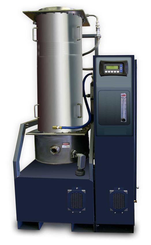
Ozone Generator Overview
Refer to Figure 1 for an overview of the ozone generator and system connections. Labels are provided on
the Ozone Generator near selected connections to assist in proper installation.
a. Connections
i. Oxygen In- ½” Female NPT Brass for oxygen supply line.
ii. Ozone Out- ¾” Female NPT Stainless Steel for ozone output line.
iii. Coolant In/Coolant Out- ¾” Female NPT PVC for coolant lines in and out of the Ozone Gen-
erator (labeled “Water In” and “Water Out”.)
iv. Electrical- Power and Ground Connections are made inside the Control Enclosure. A hole
is provided next to Specification Label for a ¾” conduit fitting. For Autotransformer equipped
models (-98 option), all electrical connections are made at the Autotransformer. Refer to Instruc-
tion Sheet 4-0902-01 in Appendix J.
v. User I/O Panel- Provides terminal blocks for all user control signal connections. A ½” conduit
fitting knockout is provided above the panel for control signal wires.
b. Operator Interface
i. Operator Interface Panel (OIP) - The OIP consists of a four line LCD Display to report status,
and Function Keys to allow control of Ozone Generator functions. See Section 4 for a complete
description of Ozone Generator functionality and control.
ii. Oxygen Flowmeter - Displays the gas flow into the Ozone Generator. Refer to Table 1 for
appropriate flow range. (Use Suction Control Valve or Injector By-pass Valve to control flow as
described in Section 3.)
iii. Coolant Flowmeter - Displays the coolant flow through the Ozone Generator in gallons per
minute (GPM). Make fine adjustments to the cooling water flow by adjusting the ball valve
mounted on the Ozone Generator. Recommended flow rates for each model are shown on the
Specification Drawings within Appendix B.
iv. Vacuum Regulator - The Vacuum Regulator is factory set to provide optimal control over a wide
vacuum range and does not require adjustment. Do not adjust unless directed to do so by
Technical Support. Call (800) 831-7133 for more information.
v. Disconnect Switch - The Disconnect Switch toggles power to the Ozone Generator. When
turned to the ON position, the OIP will initiate and system Fans will start up. For user safety, the
Control Enclosure door will not open until the Disconnect Switch is turned to the OFF position.
Important – The Disconnect Switch may also be used as an emergency stop switch.
Warranty Summary
i. Two (2) years on entire ozone generator (see page 24).
ii. Three (3) years on High Voltage Electrodes (see page 24).
iii. To prevent voiding warranty, follow all installation instructions and first call (800) 831-7133 before an
authorized technician has commissioned the unit prior to first start-up. After commissioning, the end user
is responsible for all routine maintenance outlined in Section 5 of this manual.
iv. For complete Warranty details see Section 7 of this manual.
v. Extended Warranty and Service Agreements are available. Please contact (800) 831-7133 for more
information.
INTELLIZONE™ COMMERCIAL OZONE GENERATOR Installation and User's Guide2
Ozone Autotransformer
Module (-98 Models Only)
Operator Interface
Panel (OIP)
Coolant
Flowmeter
Oxygen
Flowmeter ½” Conduit
Knockout
for User
I/O
Disconnect
User I/O
Switch
High Voltage Panel
Feed-Through Disconnect
and Cover Switch
(Power In)
Coolant Out
Breaker
Ground Coolant In
Vacuum
Terminal
Regulator
Oxygen In
¾” Conduit
Hole
Ozone Out
Specification
Lift
Label
Figure 1. Quantum Ozone Generator Overview
(CD-400 F Shown)
Number of
Model Number Voltage Autotransformer
Modules
CD-250F 207-253 VAC, 50/60 Hz, 3Ø 1 No
CD-250F-98 360-440 VAC, 50 Hz, 3Ø 1 Yes
CD-400F 432-528 VAC, 50/60 Hz, 3Ø 1 No
CD-400F-98 360-440 VAC, 50 Hz, 3Ø 1 Yes
CD-800F 432-528 VAC, 50/60 Hz, 3Ø 2 No
CD-800F-98 360-440 VAC, 50 Hz, 3Ø 2 Yes
CD-1200F 432-528 VAC, 50/60 Hz, 3Ø 3 No
CD-1200F-98 360-440 VAC, 50 Hz, 3Ø 3 Yes
Table 1. Model Number Identification
INTELLIZONE™ COMMERCIAL OZONE GENERATOR Installation and User's Guide3
SECTION 2. Installation_
System Overview
IntelliZone™ Commercial Ozone Generator accept externally supplied oxygen (O2) under pressure and
transition the gas to vacuum prior to ozone (O3) generation.
Vacuum is typically provided by a venturi injector installed directly (within a Bypass manifold) in the
process flow or in a side stream of the process flow (see Typical Ozone Delivery System Overview
Diagram in Appendix C.) The injector “pulls” the ozone into the water flow, wherein a high percentage
of the gas is dissolved. Note that the process water is not treated within the Ozone Generator, although
the process water may be used for coolant in some cases.
The ozone/water mixture then moves to the Contact Tank or Mixing Tower giving the ozone time to
react with impurities. Excess gas (high in ozone concentration) leaves the top of the Contact Tank
through a Degas Valve and moves to an Ozone Destruct. The Ozone Destruct catalytically converts the
excess ozone back to oxygen so it can be safely exhausted.
Each of the system components has its own installation instructions and maintenance requirements
that must be followed closely for safe operation of the ozone system. The Sections below describe the
connections made directly to the Ozone Generator and may refer to these other system components as
needed.
Unpacking and Inspection
a. Upon receipt, remove all crate panels and inspect Ozone Generator for evidence of shipping
damage. Immediately report any damage to the shipping company.
b. Remove bolts and crate material securing the Ozone Generator to the bottom of the crate.
Location
a. Mount Ozone Generator indoors only. Location should be cool, clean and dry.
b. Recommended Clearances
i. Ceiling clearance of 48 inches above the Ozone Generator will allow servicing of the High Volt-
age Electrodes without Ozone Module removal.
ii. Clearance of approximately 6 inches behind the unit and 30 inches in front is required for full tilt-
ing of the Ozone Module.
iii. 21 inches of clearance to the right of the unit allows full swing of the Enclosure Door.
c. Ambient Temp – Mount Ozone Generator in a climate-controlled location. Area must not exceed
100°F with Generator operating at full capacity.
Transportation
a. Whenever possible, lift and move the Ozone Generator with lifting forks inside of the Ozone Module
Base Channels. If necessary, the unit may also be lifted in between Channels or using the Shipping
Crate pallet.
Mounting
a. Prepare the mounting surface and install appropriate anchor hardware.
b. Mount using a minimum of 2 hold-down bolts in front and 2 in back, through the ½” bolt clearance
holes in the Module Base Channels. The four holes in the Enclosure base are optional.
c. Observe the recommended clearances in Section 2C where possible.
Connections
a. Oxygen- ½” Female NPT Brass. Connect external oxygen supply at the pressure and
concentration shown in Table 1.
b. Ozone- ¾” Female NPT Stainless Steel. Connect vacuum source (injector) from Process Line. Use
only properly sized Stainless Steel or PTFE tubing. Install ozone compatible Suction Control Valve
and Check Valve near the injector as shown in System Diagram (see Appendix C.)
Note: Use appropriate oxygen-safe grease on Stainless Steel pipe threads to avoid galling.
c. Coolant- ¾” Female NPT PVC. Connect coolant line into and out of the Ozone Generator. Use
only clean, filtered and non-corrosive coolant at the flows and pressures shown in Appendix B.
INTELLIZONE™ COMMERCIAL OZONE GENERATOR Installation and User's Guide4
d. Electrical
i. For units without Autotransformers, connect power conductors directly to the bottom terminals
of the Disconnect Switch inside the Control Enclosure. Connect earth ground conductor to the
Ground Terminal (identified by the symbol.) Run wires through appropriate ¾” conduit fit-
ting installed in the hole next to the Specification Label.
ii. For Autotransformer equipped models (-98 option), all electrical connections including ground
are made at the Autotransformer. Do not modify wiring within the Control Enclosure.
Refer to the Instruction sheet 4-0902-01 for further details.
CAUTION – Potentially lethal voltages. All electrical connections must be made by a licensed electrician.
Follow all applicable local and national electrical codes.
User I/O Panel
See Figure 2 for an overview of the User I/O Panel.
The User I/O Panel is located on the back wall inside the Control Enclosure. Signal wires may be run
through the ½” conduit fitting knockout provided just above the Panel.
Note: Remove existing jumpers as needed to install Control Signals. Jumpers must be left in place for
unused Relay Input signals.
a. Relay Inputs
The first six inputs (starting from the top) are Relay Input connections. All connections should be
made so that a closed contact indicates normal operation (open contact indicates fault condi-
tion.) For example, use the Normally Open contacts from a Flow Switch so that sufficient water flow
closes the switch.
Relay Input signals will affect Ozone Generator operation differently depending on the type of Input
and the current State of the Ozone Generator. See Section 4 for a complete description of States
and Ozone Generator Operation.
External (customer supplied) relays and/or switches must meet the following minimum ratings:
EXTERNAL RELAY MINIMUM RATINGS
VOLTAGE CURRENT
24 VDC 100 mA
Table 2. Electrical Ratings of Relay Inputs
i. ORP – If applicable, connect the signal from an ORP Controller to cycle ozone production on
and off based on process demand. If a second ORP input is required, the Stand-By or Stop
Inputs may be used depending on the system requirements.
ii. Dissolved Ozone – If applicable, connect the signal from a Dissolved Ozone Controller to
cycle ozone production on and off based on process demand.
iii. Remote Stand-By – Connect a switch or relay signal to place the Ozone Generator in
Stand-By mode from a remote location. Ozone Generator will not start until Remote Stand-By
switch is closed.
iv. Remote Stop – Connect a switch or relay signal to stop the Ozone Generator from a remote
location. Ozone Generator will not restart until Remote Stop switch is closed and the Fault is
cleared at the Operator Interface Panel.
INTELLIZONE™ COMMERCIAL OZONE GENERATOR Installation and User's Guide5
Enclosure Internal Customer External
Connections Connections
ORP
+24 VDC
a) Relay Inputs
Dissolved
Ozone External
Switch
Remote PLC
Stand-By Input
Remote Stop
Ambient Ozone
b) Relay Outputs
Process Flow
Switch (or External
Internal
Pump Interlock) Indicator
Relay
External
Power
Ozone Power
Supply
Indicator
Ozone Fault
Indicator
4-20mA Control c) 4-20mA Input
Optional
Resistor
Fuse
4-20mA
4-20mA Transmitter
Receiver
Figure 2. User I/O Panel
INTELLIZONE™ COMMERCIAL OZONE GENERATOR Installation and User's Guide6
User I/O Panel, Cont.
WARNING! – For user safety and Ozone Generator protection, Ambient Ozone and Process Flow Switch
connections are required. Do not operate Ozone Generator with over-ride jumpers in these locations.
v. Ambient Ozone – Connect signal from Ambient Ozone Monitor to immediately stop ozone
production in the event of an ozone leak.
vi. Process Flow Switch – Install a Water Flow Switch in the Process Line near the ozone
Injector. Install and calibrate the switch so that the switch closes only when sufficient water is
flowing to generate appropriate vacuum at the Ozone Generator. This will provide optimum
protection against water back-flow to the Ozone Generator, as well as fault-avoidance due to
vacuum loss during filter backwash.
b. Relay Outputs
Two Relay Outputs are provided to communicate the status of the Ozone Generator. These signals
may be run to a remote status display, for example, or connected to local signal lights. External
power is required and must meet the following ratings:
RELAY OUTPUT RATINGS
AC DC
MAX RESISTIVE LOAD (p.f. = 1.0) 10 A at 110 VAC 10 A at 24 VDC
MAX INDUCTIVE LOAD (p.f. = 0.4) 7.5 A at 110 VAC 5 A at 24 VDC
MAX OPERATING VOLTAGE 250 VAC 125 VDC
MINIMUM REQUIRED LOAD --- 100 mA at 5 VDC
Table 3. Electrical Ratings of Relay Outputs
i. Ozone Power Indicator – A closed Output Relay indicates ozone production is on.
ii. Ozone Fault Indicator – An open Output Relay indicates that the Ozone Generator has
encountered a Fault condition as described in Section 6 (or has been powered off). Ozone
production will cease and user intervention is required.
c. 4-20mA
i. A standard 2-wire 4-20 mA input is provided for optional external control of ozone output.
Enable the external control function through the Operator Interface Panel (see Section 4A)
4-20mA Input:
SPECIFICATION VALUE
INPUT IMPEDANCE 125 Ω
MAX CURRENT 30 mA
FUSE RATING FAST-ACTING 31 mA
Table 4.1 Electrical Ratings for 4-20 mA External Control Signal
1. Connect the 2 wire 4-20 mA signal to the 4-20 mA input + and – terminals on User I/O Panel.
2. Use shortest wire route possible.
3. Use shielded wire.
4. Ground the shield at the transmitter source only.
5. Do not ground the shield at the terminal block input.
6. Avoid noise problems by routing cable away from noise sources such as motors, high current
switches, transformers and AC wires.
INTELLIZONE™ COMMERCIAL OZONE GENERATOR Installation and User's Guide7
7. The input signal must not exceed a maximum of 30 mA. Install an optional series resistor as
needed to match the 4-20 mA transmitter output voltage and impedance to the input imped-
ance.
8. The 4-20 mA signal is interpreted as follows:
CURRENT (mA) RESULT
30 MAXIMUM INPUT RATING EXCEEDED
Table 4.2 Signal for 4-20 mA External Control Signal
Pre-Commissioning Checklist
Upon completing all of the generator system connections outlined in Section 2, complete the PRE-
COMMISSIONING CHECKLIST in Appendix B and SEND TO DEL OZONE by fax at 805-541-5452
or e-mail to o3info@delozone.com. Once form has been sent, contact DEL Ozone 805-541-1601 to
schedule commissioning.
SECTION 3. Commissioning_
Perform commissioning prior to initial start up of Ozone Generator and upon re-starting after service.
Note: If necessary, use the Disconnect Switch to shut down power at any point during Commissioning.
NOTE – Initial commissioning to be performed by Authorized DEL technicial ONLY.
Ozone Generator Check.
a. Review Pre-Commissioning Checklist (Appendix B) and correct any non-conformities.
b. Verify that Ozone Generator is mounted in an appropriate (cool, clean, indoor) location.
Support Systems Check
a. Start-up Oxygen Preparation system and verify that proper pressure (30psi) is available at the
Ozone Generator.
b. Start-up Cooling system and/or open appropriate cooling line valves.
c. Start Process circulation system and adjust injector bypass to pull a strong vacuum. The injector
should cavitate causing a rattling sound. This is normal.
d. Verify proper supply voltage at the Ozone Generator.
Initial Start-Up
a. With the Enclosure Door open, override the disconnect switch by turning the shaft extending from
the switch.
b. Turn on breaker.
DANGER! LETHAL VOLTAGES PRESENT. KEEP UNAUTHORIZED PERSONNEL AWAY FROM
ENCLOSURE WHEN DISCONNECT SWITCH IS OVER-RIDDEN.
c. PLC will automatically run through its start up and begin sequentially verifying sensor inputs in order
to proceed.
d. If applicable, Flow and Vacuum fault messages will appear on the OIP Display. Use Injector Bypass
and Suction Control Valve to balance gas flow, DO NOT ADJUST VACUUM REGULATOR. See
Section 4 (Operation) or Section 6 (Troubleshooting) for further instructions. Once gas system is
adjusted properly, the Ozone Generator will progress to the STOPPED State.
INTELLIZONE™ COMMERCIAL OZONE GENERATOR Installation and User's Guide8
e. Press F1 to start Ozone Generator. If gas flow is balanced, coolant flow is sufficient and external
contacts (ORP, Dissolved Ozone, etc) are closed, the generator will start.
f. Verify that Ozone Generator Power Level is set to 100% as indicated on the OIP Display.
g. For multiple Module models, verify proper balance of Oxygen and Coolant flow between Modules.
Since balance is pre-set at the factory, only slight adjustments should be necessary.
h. Check for water leaks in coolant plumbing. Shut down Ozone Generator and fix leaks as required.
Supply Voltage Check
a. Allow Ozone Generator to warm up for several minutes and re-check supply voltage. If supply volt-
age is not within specifications, shut down and notify facility manager.
b. If supply voltage is within specifications, press F2 to stop. Wait for the Ozone Generator to complete
it’s SHUTTING DOWN sequence.
c. Carefully turn Disconnect Switch back to OFF position.
d. Close and latch Enclosure Door.
Vacuum Regulator Check
a. Turn Disconnect Switch back to ON position.
b. Bring Ozone Generator back to READY State. Ensure that “Oxygen Save Mode” and “Auto Mode”
are OFF to allow gas flow (see Section 4.)
c. Use the Suction Control Valve to choke off vacuum to the Ozone Generator. Verify that the Ozone
Generator continues to run when flow drops to approximately 50cfh per module.
External Control Check
a. From READY State, re-enable Auto Mode (press F3) and press F1 to start ozone production. Verify
that ORP/Dissolved ozone level rises. Wait for level to reach set point (or bring set point down) to
verify that ozone turns off.
b. Check other external controls as required.
Ozone Generator is now ready for normal operation. Review Section 4 for details on control system operation and user
settings. After start up, the control system will automatically cycle the generator on and off as needed to
maintain required ozone level. Initial system start up procedures need to be followed again in the event
of a safety interlock system shut down or an interruption in the main power.
SECTION 4. Operation_
For first time startup: Perform Commissioning as outlined in Section 3.
System Overview
The Ozone Generator is controlled by a programmable logic controller (PLC). An LCD screen provides
user feedback on the status of the Ozone Generator and a keypad allows input of user settings and
control of the Ozone Generator.
a. Operator Interface Panel (OIP)
i. The Operator Interface Panel on the front of the Controls Enclosure consists of a four line LCD
display to report essential user information and a keypad to allow control of Ozone Generator
functions.
ii. The OIP has two screen modes: “PLC Message” and “Diagnostics and Settings”. Functions and
Display information will change with each mode as noted below.
Note: The PLC Message Screen has priority over the Diagnostics and Settings Screen. When an
Ozone Generator State change occurs, the display will automatically switch to the PLC Message
screen. Press ESC to return to the Diagnostics and Settings Screen.
b. PLC Message Screen - In this mode, the PLC will update the screen with current information about
the Ozone Generator’s State of operation. The “PLC Message” LED is illuminated when the screen
is in this mode. See Table 5 for function of Keys in this mode.
INTELLIZONE™ COMMERCIAL OZONE GENERATOR Installation and User's Guide9
LED is lit in “PLC
Message” Mode
RUNNING PWR SET 100%
LCD Display MODULE: 1 POWER: 100%
F3 – STANDBY MODE
F2 - STOP
Function
Keys
Figure 3a. Typical OIP Display in “PLC Message” Mode
KEY FUNCTION
SOFT KEYS. FUNCTIONS DEFINED ON
F1 – F5
SCREEN MENU
SWITCH TO DIAGNOSTICS AND SET-
ESC
TINGS MENU
UP/DOWN NONE
ENTER NONE
Table 5. Function of OIP Keys in “PLC Message” Mode
c. Diagnostics and Settings Menu - The Diagnostics and Settings menu consists of six main folder
items as shown in Figure 3b. Each folder contains user settings or diagnostic information. Use the
UP/DOWN arrow keys to scroll to the desired folder and press the ENTER key to open the folder. Use
the ESC key to exit a folder. Table 6 describes the key functions in this mode.
KEY FUNCTION
SOFT KEYS FUNCTION AS DEFINED ON THE CURRENT
F1 – F5
(ALTHOUGH NOT VISIBLE) PLC MESSAGE SCREEN MENU
ESC EXIT MENU LEVELS OR SWITCH TO PLC MESSAGE MODE
UP/DOWN SCROLL THROUGH MENU AND CHANGE SETTINGS
ENTER ENTER FOLDERS AND EDIT SETTINGS
Table 6. Function of OIP Keys in “Diagnostics and Settings” Mode
INTELLIZONE™ COMMERCIAL OZONE GENERATOR Installation and User's Guide10
┌──USER SETTINGS
│ ├──POWER SETTING 100 %
│ ├──4-20 mA MODE 1
│ └──OXYGEN SAVE MODE 1
│
├──CURRENT SENSORS
│ ├──MODULE 1 22.4 Amps
│ ├──MODULE 2 21.9 Amps
│ ├──MODULE 3 22.1 Amps
│ │
├──PRESSURE SENSORS
│ ├──MODULE 1 12.4 PSIA
│ ├──MODULE 2 12.2 PSIA
│ ├──MODULE 3 12.3 PSIA
│ │
├──OTHER DIAGNOSTICS
│ ├──RUNTIME 1234.5 HRS
│ ├──OXYGEN SENSOR 96.8 %
│ ├──4-20 mA INPUT 100 %
│ ├──PDM OUTPUT 85 %
│ │
├──FAULT CODE HISTORY
│ ├──FAULT 10 AT 1234.5
│ ├──FAULT 9 AT 1234.5
│ ├──FAULT 8 AT 1234.5
│ ├──FAULT 7 AT 1234.5
│ ├──FAULT 6 AT 1234.5
│ ├──FAULT 5 AT 1234.5
│ ├──FAULT 4 AT 1234.5
│ ├──FAULT 3 AT 1234.5
│ ├──FAULT 2 AT 1234.5
│ ├──FAULT 1 AT 1234.5
│ ├──--------END---------
└──FAULT CODE MEANINGS
├──1...............BFPD
├──2...........LOW O2 %
├──3....LOW O2 PRESSURE
├──4.........LOW VACUUM
.
.
.
Figure 3b. Diagnostics and Settings Menu Tree
i. USER SETTINGS – This folder contains all available user settings. To change any of these settings:
- Use the UP/DOWN arrow keys to scroll to the desired setting and press ENTER.
- Use the UP/DOWN arrow keys to change the setting to the desired value.
- Press ENTER to complete the change, or ESC to cancel.
1. POWER SETTING – Use Power Setting to scale ozone generation between 0 and 100%. Func-
tions only when 4-20 mA mode is NOT enabled.
2. 4-20 mA MODE – This setting may either be ON (setting = 1) or OFF (setting = 0). When this
mode is turned on, an external 4-20mA signal will scale ozone generation between 0 and 100%.
Note: If 4-20mA mode is turned on, a fault message will appear unless an appropriate 4-20mA
signal is present.
3. OXYGEN SAVE MODE – This setting may either be ON (setting = 1) or OFF (setting = 0).
When this mode is on, gas flow valves will be closed during the READY state. This reduces the
duty cycle of the oxygen system, but will result in a delay during restart of ozone production. If
this mode is off, oxygen will continue to flow during the READY state and ozone production will
begin without delay.
ii. CURRENT SENSORS – This folder contains sensor readings for the electrical current (Amps RMS)
being delivered to each Ozone Module. Only installed Modules will be listed, depending on model.
INTELLIZONE™ COMMERCIAL OZONE GENERATOR Installation and User's Guide11
iii. PRESSURE SENSORS – This folder contains sensor readings for the vacuum/pressure in each
Ozone Module. Nominal Value is 12.7 PSIA (lb/in2 absolute) at Rated Flow. Refer to Appendix H
for conversion to other units. Only installed Modules will be displayed, depending on model.
iv. OTHER DIAGNOSTICS – This folder contains various other system diagnostic values.
1. RUNTIME – Total ozone production time in hours. This timer is only incremented when ozone is
on.
2. OXYGEN SENSOR – Oxygen feedgas concentration (%).
3. 4-20 mA INPUT – Input value of the external 4-20 mA signal (%). This will correspond to the
desired power level setting if the 4-20 mA mode is used.
4. PDM OUTPUT – Percentage to which the system is being driven to achieve the desired output
power setting. This value will vary automatically as the system controls the electrical current to
the Ozone Modules.
v. FAULT CODE HISTORY – The last 10 fault codes are logged in this folder along with a time stamp.
The most recent fault is on top of the list. Refer to the FAULT CODE MEANINGS folder for definition
of fault codes.
vi. FAULT CODE MEANINGS – A reference list of the various fault codes and their meanings.
System Power Up
Caution: Before starting the Ozone Generator ensure that:
□ Commissioning has been successfully completed.
□ All electrical connections are secure and properly installed per applicable electrical codes.
□ All plumbing connections are secure and no leaks are present.
□ Breaker inside Control Enclosure is on
□ Enclosure door is closed
□ All Ozone Generator covers and panels are in place.
a. Turn the main disconnect switch to the ON position. The PLC control system and Operator Interface
Panel (OIP) will boot up.
b. The OIP will perform a self test then show the Welcome Screen. The Welcome screen will pause for
30 seconds while displaying the Model Number and Software revision.
c. When the boot sequence is complete, the Ozone Generator will enter the STOPPED State as indi-
cated on the LCD Display.
System States
Control logic is performed through States. Each Sate has particular menu control choices and
specific PLC message screens to display relevant sensor readings and progress information.
Responses to input conditions and output behavior are dependant on the current State of the
Ozone Generator. For detailed information refer to Appendix F.
a. STOPPED
i. Once the OIP has completed its self test and Welcome Screen pause, the Ozone Generator
will automatically enter the STOPPED State. The Ozone Generator will remain in this State
until a START is initiated by pressing the F1 key. Any interlocks preventing the Ozone Gen-
erator from starting are displayed on the screen. Pressing F1 will have no effect until all the
interlocks are cleared.
ii. When interlocks are cleared and START has been initiated, the Ozone Generator will verify
system vacuum, gas flow and oxygen concentration (by incrementally opening Solenoid
Valves) through the following three sequential States.
b. CHECKING VACUUM
i. If sufficient vacuum is available, the Ozone Generator will proceed to the CHECKING FLOW
State.
c. CHECKING FLOW
i. If system flow is balanced, the Ozone Generator will proceed to the CHECKING O2% State
INTELLIZONE™ COMMERCIAL OZONE GENERATOR Installation and User's Guide12
d. INSUFFICIENT VACUUM/INSUFFICIENT FLOW
i. If proper flow conditions are not attained within 2 minutes, all valves will close as a precau-
tion against water backflow. One of the following messages will appear:
1. INSUFFICIENT VACUUM if vacuum is too low or not present. Establish proper vacuum
to continue.
2. INSUFFICIENT FLOW if system flow is unbalanced. Correct vacuum and/or oxygen
flow to continue.
e. CHECKING O2 %
i. Once gas flow through the Ozone Generator is balanced, the system will pause to verify that
oxygen concentration is steadily greater than 85% for 2 minutes in order to proceed.
ii. As long as no other fault occurs, the system will remain in the CHECKING O2% State until
correct oxygen concentration is detected.
iii. Once the above system checks have been completed successfully, the Ozone Generator will
proceed to the READY State.
f. READY
i. Once gas flow and vacuum balancing has been completed, the Ozone Generator will enter
the READY State. The system will behave differently in this State depending on previously
discussed settings (Section 4A):
1. If “Oxygen Save Mode” is enabled, all valves will be closed and gas will not flow.
2. If “Oxygen Save Mode” is disabled, valves will remain open and gas will continue to
flow.
ii. Process Flow Switch – The Ozone Generator may also enter the READY State from the
RUNNING State if the Process Flow switch opens. All gas flow valves will be closed and
vacuum will be locked in the Ozone Generator. When process flow returns, the generator will
resume normal operation.
iii. AUTO MODE
1. In the READY State, the F3 key will toggle “AUTO MODE” On/Off.
2. In AUTO MODE, the Ozone Generator will automatically start or stop ozone produc-
tion as required by external control signals such as ORP, Dissolved Ozone and Remote
Standby. If ORP is high, for example, the Ozone Generator will switch to the READY
State (ozone off). When ORP drops it will return to the RUNNING State (ozone on).
g. STARTING
This is a transition State from READY to RUNNING. Gas flow valves are re-opened (if applicable)
and the Coolant Valve is opened. If vacuum and flow balance have been maintained and sufficient
Coolant flow is detected, the Ozone Generator enters the RUNNING State.
h. RUNNING
In this State, feed gas is flowing, coolant is flowing, and ozone is being produced. Ozone produc-
tion will continue until input signal(s) indicate no demand for ozone, a fault is encountered or the
user presses F2 to STOP.
i. SHUTTING DOWN
In this State, Ozone is off and feed gas flows through the system to purge residual ozone from the
module and gas lines. Time remaining is displayed on the LCD screen.
CAUTION – When shutting the Ozone Generator down for maintenance or servicing, always allow the
SHUTTING DOWN State to complete. Failure to do so may trap high concentrations of ozone gas in the
system, presenting a safety hazard. When shutdown is complete the “STOPPED” message will be dis-
played on the LCD screen.
j. FAULT
Fault conditions require the Ozone Generator to shutdown immediately to prevent potential equip-
ment damage and/or protect from a hazardous condition.
The condition that caused the Fault will be displayed on the screen. Ozone, oxygen and coolant
flow are all stopped.
INTELLIZONE™ COMMERCIAL OZONE GENERATOR Installation and User's Guide13
The situation that caused the fault must be corrected before resuming operation. Once the
source of the fault is corrected, press F4 to acknowledge and clear the Fault Screen. The Ozone
Generator will then return to the STOPPED State. Refer to Troubleshooting Section 6, if necessary.
CAUTION – Ozone gas may be trapped in the Module and gas lines after a Fault. Do not disconnect gas
lines until a SHUTTING DOWN sequence has been successfully completed.
SECTION 5. Maintenance & Service_
Preventative Maintenance Schedule
Note: Refer to Figure 4 on Page 15 of this manual. A Maintenance Log Sheet is provided in Appendix G.
Record all maintenance and service activity for warranty purposes.
WARNING! – Disconnect and lock out power to the Ozone Generator prior to opening doors or removing panels.
a. Daily
i. Verify that no Fault messages are displayed on the Operator Interface Panel.
ii. Check Gas Flowmeter(s) and Coolant Flowmeter(s) for proper level. For multiple Module
models, verify proper balance between Modules.
iii. On the Operator Interface Panel, check Module Pressure(s) Level and Current(s) for proper
levels.
b. Weekly
i. Visually inspect cabinet Air Filters for foreign objects or obstructions. Clean as needed (see
Section 5D.)
ii. Visually inspect Oxygen Filter. Clean or replace filter element as required (see Section 5E.)
iii. Look through Ozone Module Sight Glass to verify that all electrodes are lit and that no mois-
ture has accumulated in High Voltage Housing.
iv. Check for proper operation of the Ozone Destruct Unit and Water Dump Valve.
c. Monthly
i. Perform a function test of ambient ozone monitor (if installed).
d. Three Months
i. Verify proper operation of cooling fans.
ii. Test all PLC safety interlocks.
e. Six Months
i. Verify that High Voltage Transformer and Inductor thermal switches are glued in place. Check
that power connections are secure.
ii. Check that the high voltage cable is not chafing on any surfaces.
iii. Verify that High Voltage Feed-Through is secure and free of corrosion. Remove dust buildup.
iv. Inspect areas near coolant plumbing for evidence of any water leaks and resulting damage or
corrosion.
v. Perform general cleaning throughout the Enclosure.
vi. Inspect electrical system for corroded contacts or chafed wires. Clean/repair.
vii. Remove Zinc Anodes and inspect for wear. Replace as needed.
f. Twelve Months
i. Disassemble, inspect and clean Ozone Generator Module. Refer to Section 5C for instructions.
INTELLIZONE™ COMMERCIAL OZONE GENERATOR Installation and User's Guide14
Electrode and Ground Tube Cleaning – Module in Place
a. If there is at least 48 inches of clearance between the top of the Ozone Module and the Ceiling, Elec-
trodes may be serviced with the Module in place. Otherwise, Module will need to be removed as
described in Section 5C.
b. To service Electrodes with the Module in place, remove the ¼-20 hex bolts securing the Top Endcap of
the Ozone Module.
c. Disconnect ozone output line by loosening nut on compression fitting. Move tubing out of the way.
d. Remove and set aside the Endcap and Gasket. The ends of the High Voltage Electrodes are now
exposed.
e. The electrodes can be removed by gripping the exposed ends firmly and carefully pulling the electrodes
out. Twisting the electrodes slightly will help with removal.
f. Clean and reinstall electrodes and reattach Top Endcap using the procedure described in Section 5Cd.
Ozone Module Inspection and Service
WARNING! – Ozone Module is extremely heavy. Support module with proper rigging prior to loosening
bolts. Keep clear of module front while tilting.
CAUTION – When shutting the Ozone Generator down for maintenance or servicing, always allow the
SHUTTING DOWN State to complete. Failure to do so may trap high concentrations of ozone gas in the
system, presenting a safety hazard. When shutdown is complete, the “STOPPED” message will be dis-
played on the LCD.
a. Ozone Module Removal
i. Perform normal system shut down procedure.
ii. Turn off and lock out main electrical service.
iii. Remove High Voltage Feedthrough Assembly
1. Remove Cover from Conduit Fitting.
2. Remove nut and washer securing Ring Lug to High Voltage Feed-Through.
3. Loosen the Hose Clamp and pull the Conduit fitting free of the High Voltage Feedthrough.
(The grommet on the Top Panel may be pushed into the Transformer Enclosure if necessary.)
4. Remove the Feedthrough Ring Clamp and disconnect the Feedthrough by gently pulling it
from the module. Set the Feedthrough and Sealing Ring aside to avoid damage.
iv. Find the Thermal Switch at the top-rear of the Ozone Module. Disconnect the Switch at the Sealed
Connector.
v. Drain Module
1. Close the Coolant Ball Valve located behind the lower left side of the Ozone Module.
2. Disconnect the Coolant line entering the top of the Flowmeter at the Quick Disconnect fitting.
A small amount of coolant will spill out, catch as much as possible to limit spills on the Trans-
former Enclosure.
3. Move the hose to a convenient location for draining (add extension hose as required), and
reopen the Coolant Ball Valve.
4. Disconnect the Brass swivel fitting from the top of the Module. Wait for all coolant to drain
from the Module.
vi. Disconnect the oxygen inlet and ozone output lines by removing the stainless steel compression
nuts (located at the bottom and top of the Module, respectively.) Move tubing out of the way.
vii. Disconnect the module ground wire from the rear-lower flange of the CD Module.
viii.
With proper Ozone Module support in place, remove the two bolts that secure the module to the
Frame.
ix. Remove Safety Cable from the left module support.
WARNING! – The Ozone Module can now rotate on the Support Pins and may fall forward if not properly restrained.
INTELLIZONE™ COMMERCIAL OZONE GENERATOR Installation and User's Guide15
x. Carefully move Module onto a work bench with the Sight Glass facing up for further disas-
sembly.
b. Ozone Module Disassembly
i. Remove the ¼-20 hex bolts securing the Top Endcap of the Ozone Module Note: Mark
orientation of Ozone Fitting for re-assembly.
ii. Remove and set aside the Endcap and Gasket. The ends of the High Voltage Electrodes are
now exposed.
iii. Grip the exposed Electrode ends firmly and carefully pull the Electrodes out. Twisting the
Electrodes slightly will help with removal. Set the Electrodes aside to avoid damage.
iv. Remove the ¼-20 hex nuts securing the bottom High Voltage Housing to the generator.
Carefully remove and set aside the HIgh Voltage Housing and gasket.
v. The Electrodes, generator housings, and gaskets are now exposed for inspection, cleaning,
and/or replacement. See the end of this Section for Replacement parts list.
c. Ozone Module Component Inspection
i. High Voltage Housing
1. Inspect High Voltage Sockets (on High Voltage Plate) for proper tightness, damage, or
corrosion. Clean, repair or replace as needed.
2. Inspect Sight Glass for cracks, replace if necessary.
3. Inspect bottom of Housing for evidence of water intrusion and excessive corrosion.
This may indicate a Water Jacket Failure or Backflow problem. Troubleshoot cause and
replace parts as needed.
4. Inspect Gasket for damage. Replace as needed.
ii. Top Endcap
1. Inspect Top Endcap for evidence of water intrusion and excessive corrosion. Clean/
replace as needed
2. Inspect Gasket for Damage. Replace as needed.
iii. Electrodes – Inspect for deposit buildups, pitting or cracks. Replace as needed.
iv. Water Jacket – Clean thoroughly then inspect all weld seams. Replace Water Jacket if nec-
essary.
d. Ozone Module Re-Assembly
Note: It is imperative that all Ozone Module components be free of contaminants during re-assem-
bly. Remove all surface corrosion, grease, oil, lint, dirt, etc.
i. Clean Water Jacket Ground Tubes by swabbing the inside of the tubes with an alcohol-
soaked, clean, lint-free cloth (using rifle cleaner or equivalent tool.)
ii. Reinstall the lower Gasket and High Voltage Housing (sight glass should be facing up.) Apply
anti-seize compound to two opposite studs. Install washers and nuts hand tight.
iii. Clean Electrodes using an alcohol-soaked, clean, lint-free cloth.
iv. Look into the Sight Glass using a flashlight. Insert Electrodes into Ground Tubes starting at the
bottom. Line up Electrode with corresponding socket and carefully push/twist into the socket.
If an Electrode fails to line up with a socket, swap with a different electrode. If socket is dam-
aged, remove Housing and replace it. Continue inserting the remaining electrodes in the same
manner.
Note: Do not touch Electrode Glass during installation. Handle with a clean, dry, lint-free cloth.
v. Apply anti-seize compound to remaining studs on High Voltage Housing. Install washers and
nuts and tighten in groups of three in an alternating pattern using two passes. First Pass: torque
to 25in•lbs. Second pass: torque to 37+/-3 inlbs.
vi. Reinstall the Top Endcap using the same technique above (note proper orientation.)
INTELLIZONE™ COMMERCIAL OZONE GENERATOR Installation and User's Guide16
Top Endcap
Coolant
Module Temperature
Electrodes Support Switch
Zinc Bolts
Anode Control
Enclosure
Fan Coolant
Ozone Fuse for Disconnect
Module 4-20mA Module
Ground
Safety
Wire
Cable
Zinc
Anode
Vacuum
Sight Regulator
Glass
Breaker Backflow
& System Detector
High Voltage
Fuses
Housing
Coolant
Ball
Valve
High Voltage
Feed-through Oxygen
Filter
Transformer Check
Air Filters Transformer, Inductor,
Enclosure Valve
Thermal Switches and Fan
Figure 4a. Generator Overview, Maintenance and Service (Back Cover Removed)
CD-400F Shown (CD-800F and CD-1200F Typical)
Soft Start
Fuses
Figure 4b. Overview, CD-250F only
Note: NOT on CD-250F-98
INTELLIZONE™ COMMERCIAL OZONE GENERATOR Installation and User's Guide17
Ozone Module Inspection and Service, Cont.
e. Ozone Module Reinstallation
i. Move the Ozone Module to the Frame and rest on Support Brackets. Line up mounting brackets
on the back of the Water Jacket with the Frame and rotate into place. Reinstall Module Support
Bolts.
ii. Reconnect Thermal Switch connector.
iii. Connect Oxygen Inlet and Ozone Outlet lines. (Use a back up wrench on the Compression fit-
ting body when tightening the Compression Nut.)
iv. Carefully insert the High Voltage Feedthrough into the High Voltage Housing with Sealing Ring
first. Feedthrough will need to align with socket on High Voltage Plate. View alignment through
Sight Glass if necessary and press in until secure.
v. Reattach and tighten Feedthrough Ring Clamp.
vi. Place High Voltage Cover over Feedthrough. Verify that Grommet is properly installed on Top
Panel of Transformer Enclosure.
vii. Reinstall High Voltage Cable ring lug on High Voltage Feed-Through using star washers and
nut.
viii. Tighten hose clamp and reinstall conduit fitting cover.
ix. Reconnect Coolant in and out lines
Note: Coolant must enter at the bottom of the module and exit at the top.
x. Reconnect ground wire to Module.
Air Filter Cleaning
a. Perform normal system shutdown procedure
b. Air Filters are located on lower front of Controls Enclosure and (each) Transformer Enclosure.
There are two to four filters depending on Ozone Generator model.
c. Back out thumb screw on top of Filter Support Bracket.
d. Filter Bracket should slide up and free of the lower nuts. If lower nuts are too tight, back them out
slightly until Bracket slides out with Filter.
e. Inspect Filter and Gasket for damage. Order replacement Filter as needed (see the end of this Sec-
tion for Replacement Parts list.)
f. If Filter and Gasket are in good condition, the Filter may be cleaned by rinsing with warm water and
mild detergent in opposite direction of air flow (into the gasket side.)
g. Allow Filter to dry completely and reinstall.
Oxygen Filter Cleaning
a. Perform normal system shutdown procedure.
b. Depressurize Oxygen line.
c. Filter is located inside Controls Enclosure immediately after Oxygen inlet.
d. Remove Bowl by depressing red button at the top while turning the Bowl. (Red button may be out of
direct view.) Drop bowl down and pull out of Enclosure.
e. Unscrew Filter Element Retainer, and remove Filter Element. O-ring should also drop out.
f. Inspect Filter Element and O-ring. Filter Element can be cleaned by Tapping on a hard surface and
using compressed air to blow out residual dirt. If a new Filter or O-Ring is required, see end of this
section for Replacement Parts list.
g. Wipe Bowl with soft cloth. Note: If excessive moisture is present in the Bowl, check Oxygen Prepa-
ration System for proper operation.
h. If Automatic Drain in the Bowl appears dirty, disassemble and clean using compressed air.
i. Reassemble Bowl, reinstall Filter Element (with O-ring first) and Reattach Bowl. Be sure that Bowl
locks into place.
INTELLIZONE™ COMMERCIAL OZONE GENERATOR Installation and User's Guide18
Replacement Parts and Order Information
For Replacement Parts call 800.831.7133 with the following information:
a. Customer Name
b. Customer Address
c. Model Number
d. DEL Serial Number
Standard Replacement Parts List
a. Cabinet Air Filter with Gasket 9-0666-01
b. Control System Fuses (1Amp, type FLQ) 5-1557-01
c. Soft Start Fuses (3Amp, type 3AG Slow) 5-9019
d. 4-20mA External Control Fuse (31mA, type 3AG) 5-1576-01
e. Check Valve, ¾” SS 8-0697
f. Check Valve rebuild kit 8-0333
g. Oxygen Filter Element & O-ring 7-0125
h. Electrode Assembly 9-0420
i. Water Jacket Gasket 7-0772
j. 12kVA Transformer Assembly 9-0660
k. Zinc Anodes, ½” MNPT 2-0150
INTELLIZONE™ COMMERCIAL OZONE GENERATOR Installation and User's GuideYou can also read