Interactive Hand Pose Estimation using a Stretch-Sensing Soft Glove - NYU
←
→
Page content transcription
If your browser does not render page correctly, please read the page content below

Interactive Hand Pose Estimation using a Stretch-Sensing Soft Glove
OLIVER GLAUSER and SHIHAO WU, ETH Zurich, Switzerland
DANIELE PANOZZO, New York University, USA
OTMAR HILLIGES and OLGA SORKINE-HORNUNG, ETH Zurich, Switzerland

Fig. 1. Our stretch-sensing soft glove captures hand poses in real time and with high accuracy. It functions in diverse and challenging settings, like heavily
occluded environments or changing light conditions, and lends itself to various applications. All images shown here are frames from recorded live sessions.

We propose a stretch-sensing soft glove to interactively capture hand poses                   full hand pose even under dexterous articulation. These challenging
with high accuracy and without requiring an external optical setup. We                        applications require that a hand tracking solution fulfills the fol-
demonstrate how our device can be fabricated and calibrated at low cost,                      lowing requirements: 1) it must be real-time, 2) it should work in a
using simple tools available in most fabrication labs. To reconstruct the                     variety of environments and settings, and 3) it should be minimally
pose from the capacitive sensors embedded in the glove, we propose a deep                     invasive in terms of user instrumentation.
network architecture that exploits the spatial layout of the sensor itself. The
                                                                                                 In many applications, hand pose is recovered via commercial
network is trained only once, using an inexpensive off-the-shelf hand pose
reconstruction system to gather the training data. The per-user calibration is                motion capture systems (MoCap) such as Vicon [2019], but these
then performed on-the-fly using only the glove. The glove’s capabilities are                  require expensive infrastructure and markers placed on the user.
demonstrated in a series of ablative experiments, exploring different models                  Marker-less approaches to the task of hand pose estimation in-
and calibration methods. Comparing against commercial data gloves, we                         clude multiple cameras [Ballan et al. 2012; Tompson et al. 2014;
achieve a 35% improvement in reconstruction accuracy.                                         Oikonomidis et al. 2011b], or more recently, a single depth camera
CCS Concepts: • Human-centered computing → Interaction devices; •                             [Oberweger and Lepetit 2017; Oberweger et al. 2015; Tang et al. 2014;
Computing methodologies → Motion capture; Machine learning; Com-                              Wan et al. 2016] or even monocular camera [Spurr et al. 2018; Iqbal
puter graphics.                                                                               et al. 2018; Cai et al. 2018; Mueller et al. 2018; Zimmermann and
                                                                                              Brox 2017]. Despite this significant progress, vision-based methods
Additional Key Words and Phrases: hand tracking, data glove, sensor array,
                                                                                              require externally mounted cameras with the whole hand visible
stretch-sensing
                                                                                              in the image. This limitation presents a practical barrier for many
ACM Reference Format:                                                                         applications, in particular those where heavy occlusions can be
Oliver Glauser, Shihao Wu, Daniele Panozzo, Otmar Hilliges, and Olga
                                                                                              expected, such as while interacting with an object, wearing gloves
Sorkine-Hornung. 2019. Interactive Hand Pose Estimation using a Stretch-
                                                                                              or other items of clothing or while working in cluttered environ-
Sensing Soft Glove. ACM Trans. Graph. 38, 4, Article 41 (July 2019), 15 pages.
https://doi.org/10.1145/3306346.3322957                                                       ments. Thus camera-based techniques are limited to applications
                                                                                              with a controlled environment and impose physical constraints on
1    INTRODUCTION                                                                             immersive user experiences.
                                                                                                 Mounting sensors directly onto the user’s hand removes the need
Hands are our primary means to manipulate physical objects and
                                                                                              for direct line-of-sight and can improve robustness and reliability.
communicate with each other. Many applications such as gaming, ro-
                                                                                              Not surprisingly, a variety of glove-like devices have been proposed
botics, biomechanical analysis, rehabilitation and emerging human-
                                                                                              in research (e.g. [Chossat et al. 2015]) and are available commercially
computer interaction paradigms such as augmented and virtual
                                                                                              (e.g., [Cyb 2019; Man 2019]). Such approaches typically leverage
reality (AR/VR) critically depend on accurate means to recover the
                                                                                              inertial measurement units (IMUs), bend sensors, strain sensors or
Authors’ addresses: Oliver Glauser; Shihao Wu, ETH Zurich, Switzerland,                       combinations thereof to capture local bone transformations. While
{oliver . glauser, shihao . wu}@inf . ethz . ch; Daniele Panozzo, New York University, USA,
panozzo@nyu . edu; Otmar Hilliges; Olga Sorkine-Hornung, ETH Zurich, Switzerland,             potentially accurate, placing a sufficient amount of sensing elements
{otmar . hilliges, olga . sorkine}@inf . ethz . ch.                                           on a glove in order to capture all the degrees-of-freedom (DoFs)
                                                                                              of the hand is challenging due to space constraints. Hence, most
Permission to make digital or hard copies of part or all of this work for personal or
classroom use is granted without fee provided that copies are not made or distributed         existing solutions use fewer sensors than there are DoFs in the
for profit or commercial advantage and that copies bear this notice and the full citation     human hand. This inherently restricts the reconstruction fidelity.
on the first page. Copyrights for third-party components of this work must be honored.
For all other uses, contact the owner/author(s).
© 2019 Copyright held by the owner/author(s).
0730-0301/2019/7-ART41
https://doi . org/10 . 1145/3306346 . 3322957

                                                                                                       ACM Trans. Graph., Vol. 38, No. 4, Article 41. Publication date: July 2019.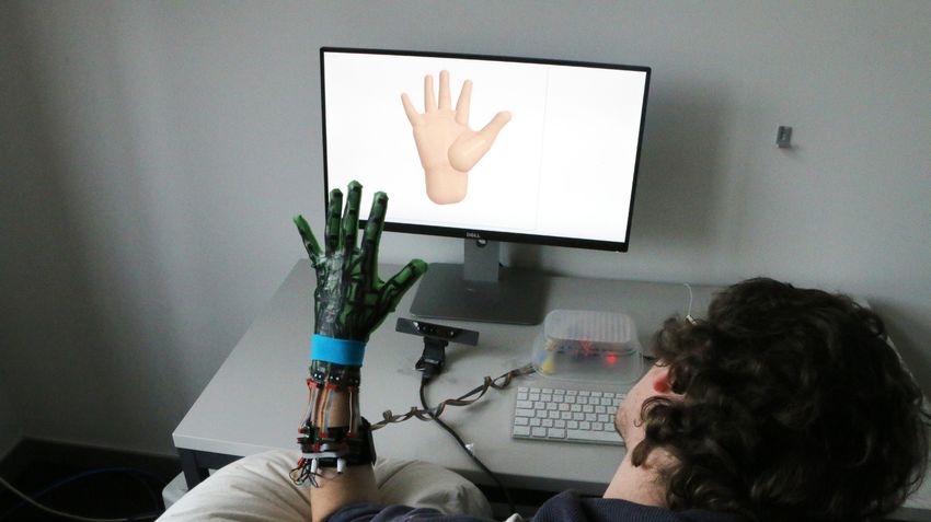
41:2 • Oliver Glauser, Shihao Wu, Daniele Panozzo, Otmar Hilliges, and Olga Sorkine-Hornung

   We propose an intrinsic (i.e., without the need for external sens-         that our solution shows substantial improvement in reconstruction
ing) hand-pose estimation approach in a thin, unobtrusive form-               accuracy (35%), which we believe may have a major impact in real-
factor. Our approach leverages two key observations: 1) it has re-            world applications, especially when paired with the low cost and
cently become feasible to produce soft, stretchable sensor arrays             simple fabrication of our device.
entirely from silicone [Araromi et al. 2015; Glauser et al. 2019], and
2) modern data-driven techniques can be leveraged to map the re-              2   RELATED WORK
sulting sensor readings (which are no longer trivially related to             The majority of hand pose reconstruction methods are based on
bone transformations) to hand poses. The combination of these two             either an external vision setup or a set of sensors embedded into a
observations leads to our contribution: a soft, self-sensing glove, con-      data glove. Most gloves employ sensors from three categories: IMUs
sisting of an over-complete sensor array (i.e., more sensing elements         (inertial measurement units), bend (flex) sensors, and strain (stretch)
than DoFs) that can accurately reconstruct hand poses without an              sensors. For a complete overview we refer to the surveys [Dipietro
optical setup and requiring only minimal calibration. Furthermore,            et al. 2008; Rashid and Hasan 2018]. Other work has used wrist worn
our glove is thin and easy to put on and take off without sacrificing         IR cameras [Kim et al. 2012] or magnetic sensing [Chen et al. 2016]
a tight adaptive fit that is crucial for high repeatability.                  for hand pose estimation, and capacitive wrist bands [Truong et al.
   The proposed glove senses local stretch magnitude exerted on               2018] or electromyography (EMG) [Saponas et al. 2009] for gesture
the embedded silicone sensors by measuring their capacity changes.            recoginition. In the following, we summarize the works most closely
These stretch-driven sensors are small, soft and low-cost. However,           related to our data glove.
the fabrication process proposed in [Glauser et al. 2019] has only
been shown to capture simple cylindrical shapes at a frame rate of               Camera based tracking. A variety of vision based approaches
8 Hz. Our main hardware contribution is a much more elaborate                 for the problem of hand pose estimation have been proposed in
sensor design in the form of a wearable glove, which requires several         the computer vision and graphics literature (cf. [Erol et al. 2007]).
improvements to the fabrication process, including integration of             Marker based MoCap approaches (e.g., Vicon [2019]) require multi-
the sensor array with a textile cut pattern, as well as a redesign of         ple, calibrated cameras and, compared to the full-body case, marker
the readout scheme to enable querying the glove at 60 Hz.                     occlusions are a more severe problem. In consequence, learning
   Since the stretch sensors are not in a one-to-one relation with            based approaches to marker labelling under occlusion have been
the degrees of freedom of the hand, the reconstruction of the pose            proposed [Han et al. 2018]. However, the need for multiple cameras
is a highly involved task. While Glauser et al. [2019] use an out-of-         restricts the applicability of such approaches. Wang and Popović
the-box deep neural network that maps capacitance to 3D vertex                [2009] propose a marker-like glove, requiring only one RGB camera.
positions for this purpose, we discover that a data representation            With the widespread availability of consumer grade depth cameras,
based on prior knowledge of geometric neighborhood and spatial                single sensor solutions have received intense attention [Sharp et al.
correspondence, both in the input and output domain, allows a                 2015; Sun et al. 2015; Tagliasacchi et al. 2015; Tang et al. 2014, 2015,
neural network to more efficiently discover the inter-dependencies            2013; Taylor et al. 2016; Wan et al. 2017, 2016; Zhang et al. 2016].
between the joints in the human hand and in consequence outper-               Depth based approaches can be categorized into model fitting based
forms several baseline architectures.                                         methods (e.g., [Oikonomidis et al. 2011a; Tkach et al. 2016]) and
   Attaining a sufficiently large and diverse training data corpus            per-frame classification [Sun et al. 2015; Tang et al. 2014; Wan et al.
for hand pose estimation is a notoriously difficult problem due to            2017; Tang et al. 2015]. Moreover, many hybrid approaches that
the absence of ground-truth acquisition approaches. While this                initialize a coarse hand pose estimate via discriminative approaches
is particularly severe in the case of (2D) image-based approaches             and then refine this via minimization of some error functional have
(where no instrumentation whatsoever may be used), we observe                 been proposed [Sridhar et al. 2013; Tkach et al. 2016; Taylor et al.
that our glove design is so unobtrusive, that it is invisible to a depth-     2016; Tkach et al. 2017; Taylor et al. 2017]. Others deploy convolu-
camera. This allows us to leverage a state-of-the-art model-fitting           tional neural networks (CNNs) to regress 3D hand poses from depth
based hand tracking approach [Tkach et al. 2017] to capture a large           images [Oberweger et al. 2015; Oberweger and Lepetit 2017; Sinha
training dataset consisting of one million samples from 10 subjects           et al. 2016; Ge et al. 2017; Tang et al. 2014; Wan et al. 2017] or even
of time-synchronized sensor readings and the corresponding joint-             from just a single RGB image [Simon et al. 2017; Spurr et al. 2018;
angle configurations, including a set of shape parameters per person,         Mueller et al. 2018; Cai et al. 2018; Zimmermann and Brox 2017].
which we release to the public domain1 to foster future research.                In contrast to vision-based approaches, our work relies only on
   To validate the utility and performance of our data capture and            intrinsic sensor readings and, once trained, requires no additional
regression setup, we carry out extensive experiments using different          external infrastructure, opening the door to usage scenarios where
calibration regimes, varying from employing a personalized model              traditional motion capture approaches are not applicable.
for a specific hand, to applying our model to different users with
significant variation in hand shapes and sizes. The quality of our               IMU sensor gloves. IMUs consist of a 3-axis accelerometer, a 3-axis
reconstruction deteriorates gracefully, offering different calibration        gyroscope and a 3-axis magnetometer. Gloves based on 15 [Fang
options depending on the accuracy required by the application.                et al. 2017], 16 [Connolly et al. 2018], or 18 [Lin et al. 2018] IMUs
Finally, we compare with two commercial gloves, demonstrating                 have been suggested to recover hand pose. The work of von Marcard
                                                                              et al. [2017] leverages 6 IMUs together with an offline optimization
    1 https://igl.ethz.ch/projects/stretch-glove                              to recover full-body pose, and Huang et al. [2018] use a bi-directional

ACM Trans. Graph., Vol. 38, No. 4, Article 41. Publication date: July 2019.
Interactive Hand Pose Estimation using a Stretch-Sensing Soft Glove •                      41:3

RNN to learn this mapping from synthetic data and reconstruct full-
body poses in real time. One major drawback of IMUs in the context
of hand pose estimation is their rigidity and bulkiness compared to
the size of human fingers.

   Bend sensor gloves. Bend (flex) sensors have been very success-
fully applied in commercial products like the CyberGlove [Cyb
2019], the VPL Glove [VPL 2019], the 5DT glove [5DT 2019] or the
recent ManusVR glove [Man 2019], with the latter also employing
two IMUs. [VPL 2019] and [5DT 2019] are equipped with optical
flex sensors. Some glove designs leverage off-the-shelf flex sensors
[Gentner and Classen 2008; Zheng et al. 2016; K Simone et al. 2007],
whereas others focus on designing novel, soft bend sensors [Kramer
et al. 2011; Shen et al. 2016; Ciotti et al. 2016]. Typically such gloves    Fig. 2. Our glove consists of a full soft composite of a stretchable capacitive
feature between 5 and 22 (CyberGlove) sensors, whereas the human             silicone sensor array and a thin custom textile glove (green).
hand has at least 25 DoFs. A larger amount of sensing elements is
difficult to place and typically increases the complexity of the glove
design and consequently the manufacturing cost (cf. CyberGlove               their stretch array sensors, combined with a learned prior, can cap-
[2019]) and may hinder dexterous and natural hand movements. In              ture dense surface deformation of simple, cylindrical human body
contrast, our design consists of a single sheet of silicone composite,       parts like a wrist, elbow or bulging biceps. For an in-depth discus-
and the amount of sensing elements is only limited by the surface            sion on different capacitive strain (stretch) sensor types and their
area and space for routing of connecting leads. We compare with              fabrication, we refer to [Glauser et al. 2019].
two state-of-the-art gloves [Man 2019; Cyb 2019] in Sec. 5.
                                                                                Calibration. To provide reasonable accuracy, appropriate calibra-
   Strain sensor gloves. Elastic strain sensors have the potential to        tion is crucial for data gloves [Kessler et al. 1995], due to specific
allow for very slim and comfortable gloves. Starting with [Lorussi           sensor characteristics and the large variations in shape of different
et al. 2005], many different strain sensor gloves, glove parts, or           hands. Calibration is often equivalent to finding model parameters,
novel sensors tailored for hand capture have been proposed. Most             such as gain, offset, or adjusting cross-coupling effects of a cus-
of the presented strain sensor gloves are resistive [O‘Connor et al.         tom hand deformation model. Min-max pose calibration [Menon
2017; Michaud et al. 2016; Hammond et al. 2014; Lorussi et al. 2005;         et al. 2003], ground truth calibration [Chou et al. 2000], and inverse
Park et al. 2017; Ryu et al. 2018; Chossat et al. 2015], either using a      kinematics (IK) calibration [Griffin et al. 2000; Hu et al. 2004] are
piezoresistive material, an elastic conductive yarn or conductive liq-       among the most common approaches. Wang and Neff [2013] ele-
uid channels. Liquid sensors are superior in terms of hysteresis, but        gantly combine all three calibration methods to build a Gaussian
their fabrication is often highly involved. Gloves based on capacitive       process regression model, allowing to reconstruct joint-angles with
stretch sensors, similar to ours, [Atalay et al. 2017] or video demos        high accuracy. Menon et al. [2003] and Chou et al. [2000] fit a hand-
by commercial stretch sensor manufacturers [Str 2019; Ban 2018],             sensor model to individual users. The work of [Menon et al. 2003]
combine the advantages of a slim form factor, no hysteresis, and             assumes specific joint angles for poses to be performed by the user,
softness. At most 15 strain sensors are used for a full glove by [Park       while [Chou et al. 2000] track a set of markers to overcome the fixed
et al. 2017], including abduction sensors. This is still significantly       angle assumption. Kahlesz et al. [2004] and Steffen et al. [2011] intro-
less than the amount of DoFs of a full hand; therefore many of the           duce models mapping from several sensors to one pose parameter
suggested designs are only demonstrated in the context of gesture            to reduce cross-coupling effects. Griffin et al. [2000] ask the user
recognition [Ryu et al. 2018; O‘Connor et al. 2017; Hammond et al.           to pose the hand while the thumb and one fingertip touch, and fit
2014; Lorussi et al. 2005] and are not suitable for continuous full          model parameters by minimizing fingertip distances. Hu et al. [2004]
hand pose estimation. Some works show pose capture of a part of              extend this method by applying a vision system, tracking fingertip
the hand [Michaud et al. 2016; Park et al. 2017]. Only [Park et al.          positions, and Zhou et al. [2010] extract user-specific calibration
2017] and [Chossat et al. 2015] (11 sensors) demonstrate the capture         parameters from a single image via a ANN. Fischer et al. [1998]
of a full hand, but without evaluating the resulting accuracy. Our           use a neural network to learn a mapping from sensor readings to
sensor design incorporates almost three times as many strain sen-            fingertip positions.
sors as the closest comparison, and to the best of our knowledge, we            We propose a simple yet effective per-user calibration procedure:
are the first to demonstrate the feasibility of accurate, continuous         First, a non-personalized model is trained to map from sensor read-
reconstruction of full hand poses from strain sensors alone.                 ings to pose parameters. For new hands, minimal and maximal
                                                                             capacitance values per sensor are captured and used to normalize
   Stretchable sensor arrays. Glauser et al. [2019] extend the capaci-       sensor readings. Note that this is different from the classic min-max
tive strain sensor concept of [O’Brien et al. 2014; Atalay et al. 2017]      calibration, where specific joint-angles or poses are assumed to cor-
and simplify the fabrication method from [Araromi et al. 2015] to            respond to the min and max values (e.g., [Menon et al. 2003]). We
achieve dense area-stretch sensor arrays. They demonstrate how               discuss the calibration details in Sec. 5.

                                                                                       ACM Trans. Graph., Vol. 38, No. 4, Article 41. Publication date: July 2019.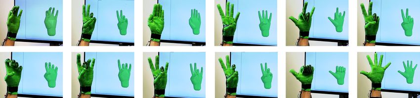
41:4 • Oliver Glauser, Shihao Wu, Daniele Panozzo, Otmar Hilliges, and Olga Sorkine-Hornung

                                                                                 placed in a certain area, Glauser et al. [2019] arrange the traces in
                                                                                 a grid structure. As shown in Fig. 3 (right), a local capacitor, also
                                                                                 called sensor cell, is formed wherever two traces overlap, and each
                                          er
                                      lay
                               tive                                              pair of traces overlaps at most once. In consequence, the number of
      Ele                  tec
            ctro        Pro
                   de                     er                                     required leads is the sum of the number of grid rows and columns,
                                     lay
                               tric
      Ele
            ctro            lec
                   de   Die               er                                     instead of the product. For the example in Fig. 3, only 8 (4+4) instead
                                       lay
                                tive
                        Pro
                            tec                                                  of 17 (4 · 4 + 1 for ground) leads are required. This space-efficient
                                                                                 design allows us to place as many as seven sensors on thin objects
                                                                                 like fingers. And for our 44 sensors on the glove, only 27 leads in 2
Fig. 3. Left: A capacitive silicone stretch sensor consists of 5 layers. When    layers are needed, compared to 45 with a non-matrix approach, a
it is deformed, its capacitance changes. Right: Conductive strip patterns        reduction of 42.5%.
(magenta and green) are embedded into the two electrode layers. Wherever
they overlap a local capacitor, which we call sensor cell, is formed. One such      Readout scheme. The matrix layout means that sensor cells cannot
sensor cell is marked with a dashed line.                                        be read directly. Furthermore, Glauser et al. [2019] experimentally
                                                                                 verified that simple variants of scanning schemes commonly used
                                                                                 in mutual capacitive touchscreens cannot be applied. Instead, they
3     COMPOSITE CAPACITIVE GLOVE                                                 introduced a time-multiplexed readout scheme, where for each of
The goal of our work is to develop a thin and lightweight glove                  the measurements a voltage is applied to a subset of traces, while
that is comfortable to wear, yet delivers high pose reconstruction               the remaining leads are connected to ground. This way, a temporary
accuracy without requiring elaborate calibration or a complex setup.             (compound) capacitor is formed, whose capacitance is measured.
   Fig. 2 illustrates our final design, consisting in a dense stretch            There exists a linear relationship between the compound capacitance
sensor array. It is easy to put on, unobtrusive to wear, and manufac-            values Cm and the desired individual capacitor values Cc [Glauser
turable at a low-cost (material cost around 15 USD, not including 60             et al. 2019]:
USD for prototype electronics). At the heart of our data glove lies                                            M Cc = Cm .                        (2)
a silicone based stretch sensor array, specifically designed for the             The rows of the rectangular matrix M encode all possible measure-
purpose of reconstructing dexterous hand articulations. Our design               ment combinations, and it transforms the sensor cell capacitances
features 44 individual stretch sensors on a hand-shaped silicone                 Cc into the measured combined capacitances Cm . The rows of ma-
sensor array, attached to an elastic textile to form a thin form factor          trix M are formed by iteratively connecting one trace from the
glove. The total weight is just 50 g and its thickness is only 1.2 mm,           top and one trace from the bottom layer as source electrode, with
making it comfortable to wear even for extended use. Our glove                   all remaining traces connected as the ground electrode. Our glove
adapts well to a range of hand sizes and shapes: one single size fits            layout has 15 traces in the bottom layer and 12 traces in the top
the hand of all members of our research group.                                   layer, resulting in 180 = 15 · 12 rows in M. Each row corresponds
   The sensor is a composite material, consisting of a textile layer             to one measurement, so that the 44 sensor cells in our glove design
paired with conductive and non-conductive silicone layers, fabri-                require 180 measurement combinations. The linear system above is
cated following a procedure inspired by [Glauser et al. 2019], but               overdetermined by design (for better robustness) and is solved in
adapted to the more complex geometry and motion of the hand.                     the least-square sense. Following [Glauser et al. 2019], we obtain
                                                                                 the capacitance by measuring the charging time. However, the pro-
3.1    Sensor design                                                             cedure and choice of resistors used in the original configuration,
   Sensor. Capacitive stretch sensors are appealing since they are               would lead to an insufficient readout rate of only 5 Hz in our setting.
based on the principle of a shape-changing capacitor, which, unlike                 The sensor readout scheme in [Glauser et al. 2019] neglects the
many resistive sensors, does not suffer from hysteresis. A capacitor             lead resistance. Therefore, high charging resistors (56 kOhm and
is formed by two conductive plates with an overlapping area A,                   470 kOhm) are required in their case to achieve physically accurate
separated by a dielectric (see Fig. 3 left). Any change in shape: width          stretch reading. In our case, the readings only need to be repeatable
w, length l or distance between the plates d, leads to a change in               but do not necessarily directly correspond to physically meaning-
capacitance C = ϵr ϵ0A/d = ϵr ϵ0lw/d, where ϵr and ϵ0 are constants.             ful stretch values. This allows us to use lower charging resistors
Therefore, the area of a capacitor can be estimated by continuously              (47 kOhm and 220 kOhm), improving the readout rates. Further, in-
measuring the capacitance:                                                       stead of solving for Cc every full cycle of combined measurements
                                              ϵr ϵ 0 A                           (180 updates), we solve every 16 updates. We experimentally found
              2
              A         A A        A d0              d    C
                    = 0 0 = 0              =            = 0,         (1)         that this setup provides good sensor readings, and that more fre-
              A0       A A        A d         ϵr ϵ0 A0
                                                      0
                                                         C                       quent solving has a negative impact on the frame rate due to the
                                                           d
                                                                                 limits of the micro-controller-host communication bottleneck. Our
assuming volume conservation holds, i.e., V = V 0 ⇔ A d =
                                                                                 readout scheme has a capture rate of about 60 Hz. To filter out noise
A0d 0 ⇔ A/A0 = d 0 /d.
                                                                                 in the readings, we mean-filter the last five frames of Cm before
  Sensor arrays. Traditionally, capacitive strain sensors are fabri-             solving for Cc .
cated individually and connected to a pair of conductive traces for                 The readings Cc are fed to a deep neural network that outputs
read-out [O’Brien et al. 2014]. To increase the number of sensors                hand poses (see Sec. 4). They can then be queried by an application,

ACM Trans. Graph., Vol. 38, No. 4, Article 41. Publication date: July 2019.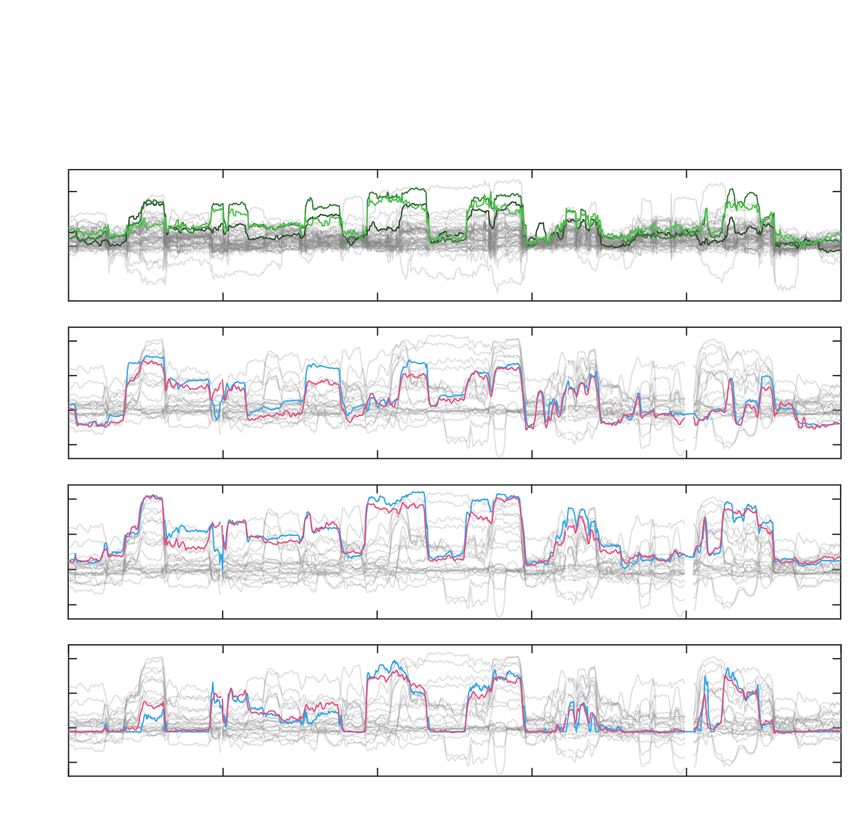
Interactive Hand Pose Estimation using a Stretch-Sensing Soft Glove • 41:5
Cuts. Thin cuts (Fig. 4 right, in purple) with rounded ends are
9
8 43 added via laser cutting on two sides of the rectangular sensors to
41 enhance the wearing comfort by increasing ventilation. They also
42 40
have a minor, yet positive, effect on the readings, since they lower
38 37
39
stretch force resistance, thus making the sensors more sensitive to
36
35 34
33 stretching parallel to the cuts. For example, sensors 21, 33 or 40,
31 30 29 located over the joints of the index finger, are much less sensitive
32
to volume changes of the finger, while sensors like 43, 37, 29 are
28
26
27 mainly sensitive to volume or diameter changes of the finger (e.g.,
25
20
due to muscle bulging). In Fig. 4 (right) the sensors more sensitive
22 21
24 23 to vertical stretch are colored in dark green, and the ones more
1
19 18 17
sensitive to horizontal stretch in light green.
16
14 6 3 0
15
3.2 Fabrication
10 7 4 2
Our glove is made of a composite consisting of a silicone sensor sheet
11
13 5 12 and an elastic textile, only requiring tools available in a modern
fablab. It is fabricated in a two-stage approach, as outlined in Fig. 5:
first, we fabricate the soft silicone sensor array (steps 1-8), covering
the back side of the glove, and then we attach textile parts to the
silicone sheet and close them up to form a soft and wearable glove
(steps 9-12).
Stage I: Silicone. The hand-shaped silicone sensor array (see Sec.
3.1) consists of two conductive, patterned layers with a dielectric
layer in-between and encapsulated by two shielding layers, shown
Fig. 4. Left: Patterns of the two conductive layers. Right: Wherever the two schematically in Fig. 3. It is produced layer by layer using the fol-
conductive layers overlap, local capacitors form (marked in green) and serve lowing steps.
as local stretch sensors. First, we cast an insulating base layer onto a glass plate, control-
ling the thickness by attaching tapes at the borders of the glass plate.
Next, a conductive layer, made from Silbione RTV 4420 silicone [Sil
e.g., to render the hand in VR or perform collision detection with
2019b] mixed with carbon black (conductive powder, [Ens 2019]),
virtual objects for interaction. In our live experiments, the hand
is cast directly onto the first layer. The laser cutter then removes,
poses are filtered by a so-called 1e-Filter [Casiez et al. 2012].
by repeatedly etching (5 times) the negative of the pattern shown
Sensor layout. The sensor layout (Fig. 4) is manually designed by in Fig. 4 (lower left), leaving the full base layer with the conductive
adding sensors in stages: (i) longer sensors directly correspond to traces on top. Then, a pure silicone dielectric layer is cast, followed
the main joints of the fingers (21-24, 32-36, 40-42) and the thumb by another conductive layer, which is also etched (Fig. 4, upper left).
(0, 20); (ii) abduction sensors in-between the fingers (16, 25-27); Finally, another insulating shielding layer is added.
(iii) perpendicular sensors on the fingers (8-9, 29-31, 37-39, 43) and Note that the conductive layers are produced with a thickness of
the thumb (1, 28); (iv) a regular grid of both horizontal (2, 4, 7, 10, 220 µm to allow for the needed leads of just 2 mm width (see Fig. 4).
17-19) and vertical (3, 5, 6, 11-15) sensors on the back of the hand. To keep the connection pads at the base of the sensor exposed, a thin
The subtle differentiation into horizontal and vertical sensors is tape is used to cover the pads before casting (for the last three layers)
the result of the ventilation cuts, explained in the next paragraph. and removed before the curing in the oven. A detailed description
Fig. 12 shows how each of these sensor categories helps to improve of the silicone mixtures and additional information on the sensor-
the reconstruction accuracy. Finally, the sensors are connected by to-read-out-circuit interconnection are provided in Appendix B.
leads in two layers, such that each pair of connected traces (from The laser cutter parameters in the etching step are Power=30,
different layers) overlap at most once. We consider reduction of the Speed=40, PPI=500 (Trotec Speedy 300 laser cutter). Using a higher
lead lengths and avoidance of stretch absorption by the nearby cuts power during the etching process would make the silicone sensor
when determining the final sensor placement. For these reasons, cross-linked with the base glass and hard to peel off in the end. After
e.g., the sensors over the knuckles (32-36, 40-42) are not centered, every full etching cycle, the sensor is cleaned from dust residue by
leaving some blank space. carefully wiping it with a towel and isopropyl alcohol.
Note that for good sensitivity with respect to finger abduction it After every casting step the sensor is cured in the oven for 20
is important that the sensors are pre-stretched when the glove is minutes at 90 ◦ C. Before curing in the oven, sensors have to be
put onto the user’s hand. It is thus crucial to fabricate the sensor left sitting for 15 minutes, to let the solvent evaporate. Otherwise,
array in the rest pose shown in Fig. 4, right. In particular, the fingers bubbles can form during curing due to the evaporation of the solvent
must be parallel without any gap in-between. from within, with the uppermost part of the layer already cured.
ACM Trans. Graph., Vol. 38, No. 4, Article 41. Publication date: July 2019.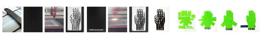
41:6 • Oliver Glauser, Shihao Wu, Daniele Panozzo, Otmar Hilliges, and Olga Sorkine-Hornung

                                       St
                                        ageI
                                           :Fabr
                                               icat
                                                  esi
                                                    l
                                                    iconesensor                                                    St
                                                                                                                    ageI
                                                                                                                       I:Makei
                                                                                                                             twear
                                                                                                                                 abl
                                                                                                                                   e

 1pr
   otect
       ive 2conduct
                  ive3l
                      aser    4di
                                elect
                                    rc 5c
                                     i   onduct
                                              ive6l
                                                  aser    7pr
                                                            otect
                                                                ive 8cut                                 9t
                                                                                                          ex t
                                                                                                             il
                                                                                                              e     10at
                                                                                                                       tach        11glue 12addvel
                                                                                                                                                 cro
  l
  ayer      l
            ayer      pat
                        ter
                          ning l
                               ayer     l
                                        ayer      pat
                                                    ter
                                                      ning l
                                                           ayer      out
                                                                       li
                                                                        ne                                cutpatt
                                                                                                                ern   t
                                                                                                                      exti
                                                                                                                         l
                                                                                                                         e           text
                                                                                                                                        il
                                                                                                                                         e  st
                                                                                                                                             rap

Fig. 5. The fabrication of a glove consists of two main stages: Fabricating the silicone sensor (1-8) and textile design for the glove (9-12). Note that the
conductive layers (2,5) are a mixture of silicone and carbon black and therefore, mostly black.

                                                                                 3.3    Comparison to [Glauser et al. 2018]
                                                                                 While our sensor array is based on [Glauser et al. 2019]), their
                                                                                 fabrication process cannot be directly applied to our setting. Our
                                                                                 sensor is a composite material made of a silicone layer (based on
                                                                                 [Glauser et al. 2019], see Appendix B) and an additional textile
                                                                                 layer. The latter is crucial in making a functional glove, since pure
                                                                                 silicone cannot be draped over complex geometries without the
                                                                                 risk of immediate damage, especially due to the large friction with
                                                                                 the human skin. In terms of the silicone sensor layer, there are
                                                                                 two major differences: (1) the readout scheme is different (Sec. 3.1),
Fig. 6. Left: The textile cut pattern is made from a large palm part, one for    allowing for a frame rate of 60 Hz (vs. 8 Hz), and (2) we seek to
each finger and 3 extra flaps for connections. Middle: Alignment of the cut      reconstruct a much more complex geometry that is articulated in
flat pattern parts with the flat, hand-shaped silicone sensor. Right: Finished   more complex ways than the simple cylindrical shapes and single
glove after closing up the flaps with textile glue.                              axis joints that shown in [Glauser et al. 2019]. The thin structures
                                                                                 of the hand require high sensor density, but offer little surface area
                                                                                 to place the sensor cells. To overcome this problem, we use much
                                                                                 thinner leads (2 mm vs. 6 mm) and smaller local sensor cells (5 x
   Finally, the sensor is cut into a hand shape with the laser cutter.           7.5 mm and 5 x 11.5 vs. 15 mm diameter). To keep the total resistance
An accurate alignment of the etching and cutting steps in the laser              of the longest leads in a useful range, the conductive layers have to
cutter is crucial to avoid cuts in the sensors, as this could lead to            be five times thicker (220 µm instead of 45 µm). As a consequence,
short circuits between the conductive layers. The overall thickness              more etching cycles are required during fabrication, and the solvent
of our sensor is 0.85 mm.                                                        must pre-evaporate to prevent bubbles from forming during curing
                                                                                 in the oven.
   Stage II: Textile. The silicone sensor array is not wearable. There
is no easy way to attach it firmly to the hand, and gluing two
sheets of silicone together is a difficult (while not impossible) task.
Attempting to put on or take off such a glove is very cumbersome
due to large friction and tightness. We attempted to attach the                  4     DATA-DRIVEN HAND POSE ESTIMATION
sensor to a standard glove, but found that it is challenging to get a            Our composite capacitive glove contains more sensors (44) than the
proper alignment with the major centers of articulation, and it is               number of DoFs in the human hand model we consider (25), however,
also difficult to do it robustly and with the needed repeatability.              the stretch sensors’ readings are not in a direct relationship with
   Therefore, we propose a simpler and more effective solution,                  the joint rotation centers of the hand. Furthermore, sensor readings
exploiting a laser cutter to cut a custom textile pattern (see Fig. 6).          vary from person to person due to the different hand geometry.
The textile parts can be attached to the silicone sensor while laying            Designing a custom mapping from sensor readings to hand joint
on a flat surface. First, a PET mask that covers the sensors and the             configurations manually is a highly complex task (e.g. [Kahlesz
cuts is placed on the sensor, then everything is covered with Sil-               et al. 2004]), which requires experiments and manual work to adapt
Poxy silicone adhesive ([Sil 2019a]), and finally, the mask is carefully         the model to the specific sensor layout. We propose instead a data-
removed, and the textile parts are placed and firmly attached.                   driven approach that can learn this highly non-linear mapping,
   In a second step, the different textile parts are closed up, using            across different sessions and users. While acquiring training data
HT 2 textile glue ([HT2 2019]), and the seams are bonded with an                 for hand pose estimation is generally difficult, gloves are a special
electric iron. A highly elastic jersey textile (80% polyamid with 20%            case since they can be unobtrusive enough to be essentially invisible
elastane) with a thickness of 0.35 mm is used. Finally, we attach                to a depth camera. Therefore, it is possible to capture training data
a wrist strap with a velcro fastener to reinforce the tightness and              efficiently using an off-the-shelf hand tracking system [Tkach et al.
ensure a repeatable alignment of sensor cells to joints.                         2017].

ACM Trans. Graph., Vol. 38, No. 4, Article 41. Publication date: July 2019.
Interactive Hand Pose Estimation using a Stretch-Sensing Soft Glove • 41:7
36 42 41 40 20
twist [y]
32 35 34 33 0
20 20 16
16 24
3
24 24 23 22 21 11 28
28 flexion [x]
15 14 6 3 11 23 19 15 28 24 20 16 12
23 19 15 abduction [z]
27
27 21 17 13
15 13 5 12 11 22 18 14 27 23 19 15 11
21 17 13 25 32 31 30
22 18 14 vertical stretch map 26 12 25 21 17 13 9
25 32 31 30 33
26 12 11 26 22 18 14 10
33
1 11
25 8 9 43 28
33 32 31 30 29
25 39 38 37 28
9
10 pose map
5
19 31 30 29 1
2
29
0 3 7 26 17 27 16
1 4 9
2 5 10
29 twist [y] 10 18 4 2 16
7 sensor layout horizontal stretch map hand pose layout
8
flexion [x]
4 abduction [z]
Fig. 8. The geometric correspondences between the input (sensor layout on
the left) and output features (hand model on the right) should be considered.
Fig. 7. Left: Our training data capturing setup. 1) Hand with glove; 2) Re- Both the input and the output can be naturally ordered in corresponding
alSense SR300 depth camera; 3) computer running [Tkach et al. 2017]; 4) grid structures.
pillow for comfort; 5) blue segmentation wristband as required by [Tkach
et al. 2017]. Right: The 34 hand pose parameters proposed by [Tkach et al. Sensor readings Min-max Input stretch Network Predicted pose Pose from depth
2017]. Our glove only captures the 25 degrees of freedom in color. The DoFs (from the glove) normalization maps (5x5x2)
in gray are the global translation and rotation, and the rotation of the wrist;
global pose parameters cannot be captured using only stretch sensors.
Loss
Any standard neural network architecture could be used in our
Predicted Ground truth
setting, including fully connected networks (FCN) and long short- pose map pose map
term memory networks (LSTM). However, we observe that these
standard approaches struggle to exploit the geometric layout of our Fig. 9. From left to right: The sensor readout is normalized by the hand-
data. By constructing an ad-hoc data layout and a network that im- specific min-max, arranged in two 5x5 stretch maps, and fed through a U-Net
plicitly encodes the sensor geometry and topology, we considerably network that predicts a 5x5 pose map. The loss is the L 2 -norm difference
improve the accuracy over standard baselines. between the predicted pose map and the ground truth pose map derived
from the hand poses captured by [Tkach et al. 2017].
4.1 Data acquisition
Our setup for capturing training data is shown in Fig. 7 (left). For movement (parameters 9, 10, 11, 12, 29 in Fig. 8). Meanwhile, some
capturing the reference hand poses, we use an inexpensive Intel high-level hand gestures, like the clenching of a fist, cause more
RealSense SR300 depth camera [Rea 2019]. Depth frames are fed to uniform sensor actuation, which should be encoded globally and
the (unmodified) algorithm of [Tkach et al. 2017], which requires hence makes a priori definition of these inter-dependencies difficult.
a blue strip on the wrist for depth segmentation. We use their cali- Training an FCN to learn such global-local information is theoreti-
bration method to compute the hand shape parameters per user. To cally possible, but practically it would require excessive amounts
capture meaningful training data, a good synchronization between of model capacity, training data, and hyper-parameter tuning. We
the different data sources is crucial. To this end, we incorporate opt instead to directly build this geometric and topological prior
our code for communication with the glove sensor into the publicly into our network architecture to regularize the learning process and
available source code of [Tkach et al. 2017]. This allows for unified improve the reconstruction performance.
collection, evaluation and logging of both sensor and pose data. We use a fully convolutional neural network (CNN) and 2D grid
representations as input and regression target. More specifically,
4.2 Data representation and network we use 5 × 5 matrices to organize our input and output data. Fig. 8
For N frames in the training data, the input X = {x i }i ∈N ⊂ R44 shows how we map sensor cell readings and pose parameters to 2D
to our regression model is the readout from the 44 stretch sensors, grids, each capturing the spatial relationships. We use one matrix
while the target output Y = {yi }i ∈N ⊂ R25 are the 25 hand pose to organize the output, but a stack of two for the input, since each
parameters as defined in [Tkach et al. 2017], covering the full pose sensing location has two types of sensors measuring horizontal and
DoFs of the hand (see Fig. 7). vertical stretch (see Sec. 3). For example, both sensors 29 and 33
are located around the knuckle of the index finger, but each sensor
Data representation. Our key observation is that the spatial cor-
captures different stretch directions.
respondences between input and output features should be con-
sidered. A meaningful ordering and organization of features make 2D network. We use the U-Net network architecture [Ronneberger
the learning task easier. For example, a group of nearby sensors on et al. 2015] to transfer the organized sensor readout to hand pose
the thumb (sensor cells 0, 1, 2, 11, 16, 20, 28 in Fig. 4, right) taken parameters. The downsampling and upsampling structure of the
together should have a higher impact on the prediction of the thumb network can encode the global information, while the symmetric
ACM Trans. Graph., Vol. 38, No. 4, Article 41. Publication date: July 2019.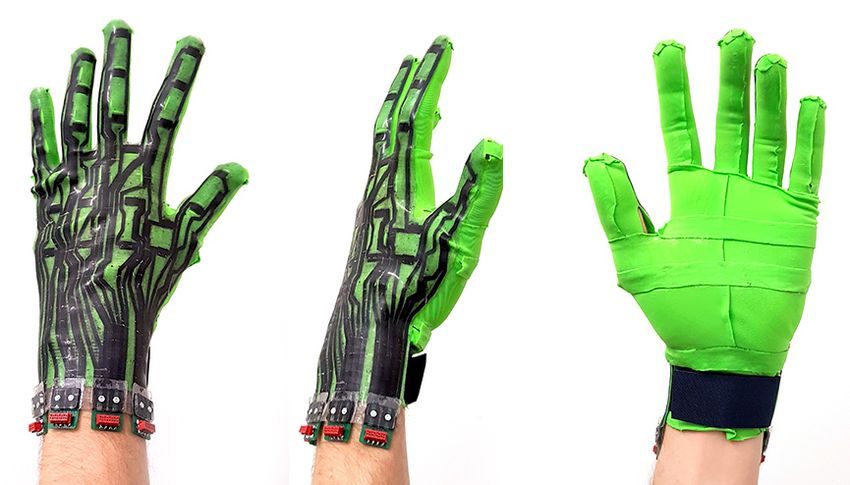
41:8 • Oliver Glauser, Shihao Wu, Daniele Panozzo, Otmar Hilliges, and Olga Sorkine-Hornung

skip connections between the encoder and the decoder can preserve             and shapes. The hand length varies from 17 to 20.5 cm, the width
the local correspondences. Fig. 9 illustrates the structure of U-Net          from 9 to 11 cm, and the aspect ratio of length to width from 1.6 to 2.1.
and how the network transforms the 2D sensor data to hand poses.              For each person we capture five sessions using our data acquisition
                                                    Í25
We use L 2 loss for our regression task, Lreg = i=1        ŷi − yi 2 ,       setup; each session lasts about 5 minutes. During three of the five
where ŷ is the prediction and y is the target pose parameter.                sessions, the participant keeps the glove on continuously, while
  Experiments show that our model compares favorably to alter-                in-between the other two sessions the glove is taken off. We refer to
native network architectures. We provide a comparison against                 these two regimes as intra-session and inter-session, respectively. To
baselines in Sec. 5.4 and describe the experimental setup in detail in        encourage the participants to explore the space of hand poses fully,
Appendix A.                                                                   we show a printed gallery of example poses during the recording
                                                                              sessions. During data acquisition and method development, one of
4.3    Data processing                                                        our gloves was in use for over 25 hours (cumulative) — consistently
We improve our data quality by removing outliers and by using a               capturing sensor data in high quality.
min-max normalization method for calibration. That is, the input to
our network is the processed and mapped sensor data, see Fig. 9.              5.2   Evaluation on hand pose capture
                                                                              We envision a standard scenario for our hand capture method, in
   Outlier removal. We remove frames that are likely to be outliers           which the proposed neural network is trained only once, preferably
by detecting finger collisions, since they indicate unfeasible poses.         on a large data set containing samples from different hands. This
We filter out frames where the collision energy defined in [Tkach             way, a new user only needs to execute the on-the-fly calibration
et al. 2017] is above 80, indicating that the estimated pose is likely        method for less than a minute before using the glove for interaction.
unnatural and wrong. This filter only removes about 2% of the data.             In our experiments, we refer to models that are trained using the
   On-the-fly calibration. Ideally, the per-sensor reading magnitude          data from all participants except leaving one participant out as test
should be normalized to become insensitive to the hand size. We               data as generic models. We also evaluate personalized models, which
observe that, once the glove is put on, the minimum and maximum               are trained on the data from one person only. This allows for even
magnitude of each sensor’s readings is fixed, which can be used to            more accurate pose reconstruction and provides further insight into
normalize the sensor data. Therefore, we find that a per-sensor min-          the capabilities of our glove. Table 1 summarizes results of all our
max calibration is a reasonable trade-off between cost and accuracy.          models. For all experiments we used a medium sized glove (20×12.5
The key is to find the min and max magnitude after the glove is put           cm); despite the single size, it can handle a large variety of hands.
on. In practice, we propose a short calibration phase, where the user         The most significant error is produced by the smallest hand (last
should freely explore different extreme poses, yielding the min and           row of Table 1) – for a more accurate tracking, a smaller size glove
max values per sensor, which we then use to normalize the sensor              would be required.
data to the [−1, 1] range. To make this process even more robust,
                                                                                 Personalized and Generic models. For the personalized model, we
we use a median filter (over 20 frames) while extracting the min and
                                                                              perform experiments on two types of data: using training and testing
max values. This simple calibration method works surprisingly well
                                                                              on intra-sessions only and using both types of sessions for training,
in practice, due to the complexity and tightness of our soft glove,
                                                                              tested on an inter-session. For the former, we use two sessions to
which provides a proper alignment.
                                                                              predict the other one. For the latter, we use three intra-sessions and
                                                                              one inter-session to predict the other inter-session. The intra-session
5     RESULTS
                                                                              samples usually have better performance than inter-session ones.
We show how our glove and the symbiotic data-driven hand pose                 This is due to better alignment of the glove during a continuous
reconstruction method can capture accurate hand poses (Sec. 5.2)              session. The Intra and Inter columns in Table 1 show the mean
on a large dataset (Sec. 5.1). We compare our glove’s performance             angular reconstruction errors for ten different hands. On average,
on a pose sequence with two commercial state-of-the-art gloves                the mean error for the intra-sessions is 5.8 degrees versus 6.2 for
(Sec. 5.3). Finally, we evaluate the proposed network architecture,           the inter-sessions. The small error difference suggests that our soft
contrasting it with alternative baselines (Sec. 5.4).                         glove provides consistent alignment across different sessions even
   In the setting where a new glove user only needs to perform                when the glove is taken off in-between. See Fig. 10 for example
a minimal on-the-fly calibration (min-max normalization using a               frames from a real-time capture session.
generic, pre-trained model), we achieve an overall mean error of                 A generic model is crucial for real-world applications aimed at
only 7.6 degrees. In a comparison sequence, with a mean pose error            a wide and diverse audience, since training a personalized model
of 6.8 our glove outperforms the ManusVR glove (mean error: 11.9)             is time consuming (2 hours or more) and requires additional equip-
and the CyberGlove (mean error: 10.5). The proposed 2D network                ment (depth camera and GPU). We evaluate the approach in two
architecture can achieve a mean error of about 1 degree lower than            variants: with and without using the calibration method described
the baseline fully-connected network.                                         in section 4.3. In the case without calibration, a per sensor min-max
                                                                              values over all users are obtained from the training data and applied
5.1    Dataset                                                                for normalization, both in training and in testing. Columns (3) and
Our experiments are performed on a large data set1 captured from              (4) in Table 1 show the effectiveness of our calibration method: the
10 people (except where noted), including a wide range of hand sizes          average pose reconstruction error is 7.6 degrees with calibration

ACM Trans. Graph., Vol. 38, No. 4, Article 41. Publication date: July 2019.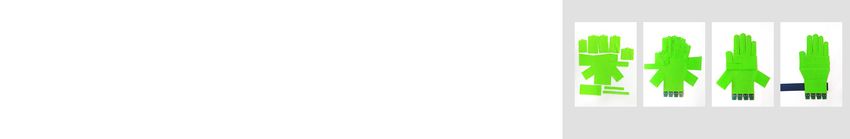
Interactive Hand Pose Estimation using a Stretch-Sensing Soft Glove •                       41:9

                          Fig. 10. A gallery of real-time session frames showing diverse poses predicted by a personalized model.

Table 1. Mean pose angle errors (in degrees) over sessions captured from           Application scenarios. Our method supports five standard appli-
people with different hand sizes and aspect ratios. The Size column lists        cation scenarios, summarized in Table 1:
bounding box volume in cm3 , and the second column gives the bounding
box dimensions in cm. We report different scenarios: Personalized models,           (1) An intra-session personalized model gives the best perfor-
trained on sessions (1) with the exact same alignment like the test session,            mance, but it requires to always keep the glove on.
or (2) when the glove is taken off in-between; generic models trained on            (2) If a depth camera is available to the user, personal training
sessions from the other 9 participants (leave-one-out): (3) uses the per-               data (20 minutes) can be captured with [Tkach et al. 2017]
feature min-max sensor data obtained from the training data, and (4) uses
                                                                                        and used to train a personalized model for about 2 hours.
the personalized, on-the-fly min-max calibration. (5) Generic model fine-
                                                                                    (3) If there is no time or ability (e.g., in a rehabilitation context)
tuned with a short (5 minutes) session of personal training data. External
hardware refers to the depth camera and GPU necessary for training data                 for training and calibration, our generic model can be used,
capture and processing.                                                                 combined with the per sensor min-max values extracted from
                                                                                        the training set.
                                                                                    (4) By first exploring some hand-poses to gather personal min-
        Hands           Personalized           Generic         Fine-tuned
                                                                                        max values on-the-fly and then using these values to nor-
                         (1)      (2)       (3)      (4)           (5)                  malize the sensor data, the accuracy of the generic model
 Size       L×W×H
                        Intra    Inter   w/o Calib w Calib.       Tuned                 can be significantly improved, within less than a minute of
 940     19×11×4.5       4.8      5.5       6.4          6.6       5.7                  calibration time.
 792     19×9.5×4        5.3      6.8       7.9          7.0       6.1              (5) A trade-off alternative to scenarios (2) and (4) is to capture
 792      18×11×4        6.2      7.8       8.6          8.5       6.6                  only 5 minutes of personal training data and fine-tune the
 836      19×11×4        5.2      5.2       7.3          6.9       5.6                  generic model for about 15 minutes.
 850    18×10.5×4.5      6.8      6.3       8.1          7.3       6.8
 1025    20.5×10×5       5.1      5.9       8.5          7.5       6.4           Options (3) and (4) require only the glove and a pre-trained model,
 840     20×10.5×4       5.2      5.9       8.8          8.0       7.2           while the others need a depth camera and a GPU to train or fine-
 680      17×10×4        5.6      5.7       8.6          8.2       6.7           tune the model. We believe that (4) is the most practical scenario,
 800      20×10×4        6.1      6.5       9.0          7.3       6.0           but applications requiring higher accuracy might benefit from a
 612       17×9×4        7.5      6.6      10.1          9.1       8.1           custom model (2) or (5). In practice, all of our models can capture
 Average error           5.8      6.2       8.3        7.6         6.5           hand poses reasonably well, and a visual comparison of models (2),
 Time investment         2h      2.5 h       0        1 min      20 min          (4) and (5) is shown in Fig. 11.
 External hardware       Yes      Yes       No         No         Yes
                                                                                    Number of sensors and training data. To illustrate the benefits of
                                                                                 a dense sensor array, we run an ablation study on the number of
                                                                                 sensor cells used, to simulate glove designs with fewer sensors (see
versus 8.3 without. An angular reconstruction error of 7.6 is satisfac-          Fig. 12). The results show that using more sensors leads to higher
tory for many applications (see Fig. 16 and the supplementary video              reconstruction accuracy, an 28% decrease in the mean error when
for a visualization of different reconstruction errors). To further im-          going from 14 to 44 sensors.
prove the reconstruction quality with minimal personalized data, we                 Our training, validation, and test datasets for the personalized
apply fine-tuning on then unseen data. That is, we load the network              models contain 85K, 10K, and 15K samples, respectively. The num-
parameters from a pre-trained generic model and then use a small                 bers of samples for the non-personalized model are 800K, 90K, and
learning rate of 1 × 10⁻⁶ and batch size of 64 to further optimize               120K. To study the necessity of using such a large training data set,
all the network parameters, which helps in avoiding catastrophic                 we gradually and randomly remove parts of our training data; the
forgetting. The results are reported in column (5) of Table 1; they              resulting reconstruction errors of the personalized model (2) and the
are comparable in performance to a personalized model, but require               generic model (4) are shown in Table 2. The drop in reconstruction
a much lower investment of time.                                                 accuracy demonstrates the benefit of having a large dataset, and

                                                                                           ACM Trans. Graph., Vol. 38, No. 4, Article 41. Publication date: July 2019.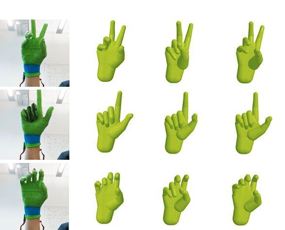
41:10 •               Oliver Glauser, Shihao Wu, Daniele Panozzo, Otmar Hilliges, and Olga Sorkine-Hornung

                 Ref
                   erenc
                       e        Per
                                  sonal
                                      i
                                      zed(
                                         2)         Gener
                                                        ic(
                                                          4)              Fi
                                                                           ne-
                                                                             tuned(
                                                                                  5)   Table 3. Generalization to a different glove: This table summarizes errors
                                                                                       when evaluating model variants on a training session captured with Glove
                                                                                       II. From left to right: Generic model trained on Glove I data only; Generic
                                                                                       (Glove I) model fine-tuned with 5 minutes of data from Glove II; Personalized
                                                                                       model trained on Glove II only.

                                                                                              Model         Generic w calib.    Fine-tuned     Personalized
                                                                                              Trained on       Glove I          Glove I & II     Glove II
                                                                                              Error                8.80             5.73            5.30

                                                                                       Fig. 13. Glove II can predict hand poses with reasonable accuracy using a
Fig. 11. Visual comparison of different models on three example frames.                model trained only on the data captured with Glove I.
From left to right: ground truth pose, reconstruction of personalized (2),
generic (4), and fine-tuned (5) models. While all models manage to capture
these poses well, the personalized model (2) performs best. We carefully
chose these frames to highlight the differences. Most poses have visually              fabrication procedure, we fabricate a second glove (Glove II ) and
similar results for all models as shown in the accompanying video.                     assess how well a model trained on data from Glove I predicts
                                                                                       poses (Fig. 13) using readings from Glove II. Table 3 summarizes
                 9                                                                     the results, they are very encouraging, especially given that our
                                                                                       current fabrication process includes some manual steps (see Sec. 3).
            8.5                                                                        We believe that an automated, industrialized version of our glove
                                                                                       fabrication process could further improve the reproducibility of our
Mean error [°]

                 8
                                                                                       composite glove.
            7.5                                                                           Object interaction. In Fig. 1 and the supplemental video, we demon-
                                                                                       strate our glove interacting with different objects. In general, touch-
                 7
                                                                                       ing or pressing onto capacitive sensor arrays influences the readings
                                                                                       due to body capacitance or deformation of the local capacitors. But
            6.5
               10          15     20      25       30        35          40      45    usual grabbing and holding of objects makes contact mostly occur
                                        Number of sensor cells                         on the inside of the hand or at the finger tips where no sensors
                                                                                       are placed. Glauser et al. [2019] illustrate the effect of touching a
Fig. 12. As the number of sensors increases, the mean reconstruction error             capacitive sensor array in an experiment.
of a captured session decreases: from 8.67 with just 14 sensors covering the
main joints to 6.75 for our full glove with 44 sensors.
                                                                                       5.3   Comparison to state-of-the-art data gloves
Table 2. This table shows that the mean session error increases if less                We compare our glove to two state-of-the-art commercial glove
training data is available (or used). The number of samples in the training            products: a data glove by ManusVR [Man 2019] and the Cyber-
data is 85K for the personalized and 800K for the generic model.                       Glove II [Cyb 2019] by CyberGlove Systems LLC. To the best of our
                                                                                       knowledge, the ManusVR glove has ten bend sensors and 2 IMUs,
                     Percentage          100%    75%    50%       25%     10%
                                                                                       while the CyberGlove II is equipped with 22 flex sensors. Before the
                                                                                       evaluation, we calibrate the two state-of-the-art gloves with their
                     Personalized (2)    5.50    6.32   6.47      6.57    7.14         proprietary software. Both routines ask the user to perform a given
                     Generic (4)         6.57    6.98   7.51      7.96    9.85
                                                                                       set of hand poses and only take a matter of minutes, comparable in
                                                                                       time investment to our min-max sensor normalization, which we
                                                                                       use for the comparison (generic model (4)). The gloves are queried
hence the importance of our unobtrusive glove that allows for a
                                                                                       through the provided SDKs to record pose data.
convenient data acquisition setup.
                                                                                          For each of the three gloves (ManusVR, CyberGlove and ours) the
  Generalization to a different glove. In all the experiments presented                same sequence of 60 hand poses and a duration of about 3 minutes
so far, we use a single glove prototype (Glove I ), for both training                  is recorded. Alongside, the hand pose angles are also captured by
data capture and testing. To evaluate the reproducibility of our                       the depth tracking system [Tkach et al. 2017], which we use as

ACM Trans. Graph., Vol. 38, No. 4, Article 41. Publication date: July 2019.
Interactive Hand Pose Estimation using a Stretch-Sensing Soft Glove • 41:11
100 Table 4. Comparison of different networks for the personalized model in
terms of mean angle-error in degrees. (2). From left to right: five different
80 Manus
Cyber network architectures. From top to bottom: varying amounts of network
60
Ours
parameters. We adjust the sizes or numbers of layers for each network to
meet the target number of parameters.
Pose angles below Error [%]
40
7 key poses, see Figure 16
20 Network size FCN LSTM ResNet U-Net CGAN
0 3M 6.63 5.81 6.06 5.63 5.59
100 13M 6.95 6.02 6.12 5.50 5.51
80 Manus
50M 7.10 6.38 6.20 5.55 5.47
Cyber
Ours
60
Table 5. Comparison of different networks for the generic model in terms
40
of mean angle-error in degrees. (4), trained on the leave-one-out dataset.
whole comparison sequence
20 From left to right: five different network architectures. From top to bottom:
varying amounts of network parameters, similar to Table 4.
0
0 5 10 15 20 25 30 35 40 45 50
Error limit [°]
Network size FCN LSTM ResNet U-Net CGAN
Fig. 14. Top: Cumulative error plot of the key poses, comparing different 3M 7.64 7.68 7.28 6.81 7.09
gloves. Over the key poses, our glove predicts 92% of the angles below an 13M 7.58 7.65 7.35 6.57 6.50
error of 15 degrees (CyberGlove: 79%, ManusVR: 75%). Bottom: Cumulative 50M 7.98 7.76 7.18 6.65 6.61
error plot over the whole comparison session.
FCN, but it tends to over-smooth some high frequency poses, like
ground truth. This choice might introduce a bias in the compari- the touching of two fingers. Among the three 2D-based networks,
son due to the use of the same tracking system for training data ResNet already outperforms the FCN baseline considerably, but
acquisition. The angles received from the ManusVR, and the Cyber- leaves room for improvement. Both U-Net and CGAN achieve high
Glove are mapped (following the description in the SDK) to the 25 reconstruction accuracy. In our experiments, the predicted poses
degrees of freedom of [Tkach et al. 2017]. Some pose angles come of U-Net are visually more stable than those predicted by CGAN.
with an offset, therefore all angles from the two state-of-the-art Thus the 13M U-Net is used for all other experiments. It yields the
gloves are shifted, so that in the first frame of the recorded sequence lowest error for both personalized and generic models (Tables 4 and
they exactly match the ground truth. Over the whole sequence, the 5). Experiments with networks with fewer than 3M parameters lead
ManusVR glove has a mean error of 11.93 degrees, the CyberGlove to an increased error. For comparison, we also trained an SVM on
10.47 degrees and ours 6.76 degrees — this is 35% lower than the the data of Table 5, which results in a higher but still acceptable
next best result. As the sequences are not exactly the same, in Fig. error of 7.8 degrees.
16 we additionally show seven poses of the comparison sequence The models compared here cover a broad spectrum of modern
with the corresponding mean error over all degrees of freedom. Fig. machine learning techniques. An exploration of more advanced
14 (top) shows a cumulative error plot comparing the percentage network architectures against our baselines, like a combination
of angular degrees of freedom below a specified error threshold of LSTM and CNN, would be an interesting direction. Hence, we
(on the x-axis) for the seven poses shown in Fig. 16. We observe release all our training data1 .
that 92% of the angles have an error below 15 degrees for our glove,
while for the CyberGlove it is 79% and the ManusVR glove 75%. The 6 CONCLUSION AND FUTURE WORK
lower part of Fig. 14 shows a cumulative error plot for the entire In this paper, we focus on the core task of a data glove — capturing
comparison sequence. accurate hand poses. Furthermore, an optimal data glove should
be comfortable to wear, real-time, low cost and easy to use. We
5.4 Comparison of networks achieve these goals via several technical contributions, including
We report results from experiments with two 1D baselines (FCN, a glove-adapted stretch sensor layout and fabrication, a wearable
LSTM) and three types of 2D network architectures: ResNet [He composite of silicone and textile layers, an improved sensor readout
et al. 2016], U-Net [Ronneberger et al. 2015], and conditional gen- scheme to achieve interactive frame rates, a structure-aware data
erative adversarial network (CGAN) [Isola et al. 2017]. In Tables representation and a minimal on-the-fly calibration method. Ex-
4 and 5 we compare the five types networks on our personalized tensive experiments exploring different scenarios demonstrate the
model (2) and generic model (4). In general, the 2D-based networks power of our data-driven model and the capabilities of the proposed
are faster to converge and lead to lower reconstruction error. The stretch sensing glove.
performance of FCN is not satisfactory, especially when the training To further improve the functionality and applicability of our glove,
set is not diverse, as in the case of the personalized model. LSTM some essential features and many intriguing extensions are to be
yields smooth results with higher reconstruction accuracy than explored in the future.
ACM Trans. Graph., Vol. 38, No. 4, Article 41. Publication date: July 2019.You can also read