Inverse Calculation of Timber-CFRP Composite Beams Using Finite Element Analysis
←
→
Page content transcription
If your browser does not render page correctly, please read the page content below
https://doi.org/10.3311/PPci.16527
                                                                                                               Creative Commons Attribution b
                                                                                                                                                   |437
                                                Periodica Polytechnica Civil Engineering, 65(2), pp. 437–449, 2021

Inverse Calculation of Timber-CFRP Composite Beams Using
Finite Element Analysis

Khaled Saad1*, András Lengyel1

1
    Department of Structural Mechanics, Budapest University of Technology and Economics, H-1521 Budapest, P.O.B. 91, Hungary
*
    Corresponding author, e-mail: khaled.saad@epito.bme.hu

Received: 25 May 2020, Accepted: 02 December 2020, Published online: 11 December 2020

Abstract
This study focuses on the flexural behavior of timber beams externally reinforced using carbon fiber-reinforced polymers (CFRP).
Linear and non-linear finite element analysis were proposed and validated by experimental tests carried out on 44 timber beams
to inversely determine the material properties of the timber and the CFRP. All the beams have the same geometrical properties
and were loaded under four points bending. In this paper the general commercial software ANSYS was used, and three- and two-
dimensional numerical models were evaluated for their ability to describe the behavior of the solid timber beams. The linear elastic
orthotropic material model was assumed for the timber beams in the linear range and the 3D nonlinear rate-independent generalized
anisotropic Hill potential model was assumed to describe the nonlinear behavior of the material. As for the CFRP, a linear elastic
orthotropic material model was introduced for the fibers and a linear elastic isotropic model for the epoxy resin. No mechanical model
was introduced to describe the interaction between the timber and the CFRP since failure occurred in the tensile zone of the wood.
Simulated and measured load-mid-span deflection responses were compared and the material properties for timber-CFRP were
numerically determined.
Keywords
spruce, CFRP, reinforcement, material properties, inverse computation, finite element

1 Introduction
Currently wood is a widely used material for different                           polymer (FRP) composites which may reduce these kinds
types of structures especially the lightweight construc-                         of problems and which might also be a permanent solution
tions. The increasing of the loads such as the dead loads                        to strengthen timber elements due to their many advan-
and the aging of timber may be significant reasons for the                       tages such as corrosion resistance, lightweight and flexi-
demolition of some pre-existing structures. In most cases,                       bility, high elastic modulus and high strength, especially
the cost of replacement of the destroyed timber structures                       when the load-bearing capacity and the ductility are in
is high so it may be preferable to repair or strengthen the                      demand to be increased.
timber elements. Some conventional strengthening/rein-                              The application of fiber-reinforced plastic materials
forcing methods for wood structures are used such as                             started many years ago in the 1960s when the use of fiber-
using steel plates or bars, and sometimes aluminum plates.                       glass (GFRP) for the strengthening of the timber struc-
These types of methods, yet, could lead to an increase in                        tures took place [1]. Nowadays, in some engineering
the dead loads, high transportation, and installation costs.                     applications, the engineers started to use the carbon fiber
It is important to mention that some traditional rehabili-                       reinforced polymers (CFRP) which have recently proved
tation methods and procedures may force us to use some                           their significantly positive effects on the structural behav-
mechanical connections such as bolts, nails and so on.                           ior: enhancing the structural performance of sawn timber
On the other hand, this could not involve good reactions                         beams or glued-laminated beams, increasing the ductility
from the deteriorated timber elements since the steel com-                       and bearing capacity of the timber elements. Furthermore,
ponents are oversensitive to corrosion, add to this the alu-                     for rehabilitating and repairing the pre-existing structures
minum plates may buckle when applying thermal loads.                             such as bridges or historic structures. Usually, the rein-
Nowadays, it is advisable to use the fiber-reinforced                            forcing elements are sheets or rods parallel to grains and

Cite this article as: Saad, K., Lengyel, A. "Inverse Calculation of Timber-CFRP Composite Beams Using Finite Element Analysis", Periodica Polytechnica Civil
Engineering, 65(2), pp. 437–449, 2021. https://doi.org/10.3311/PPci.16527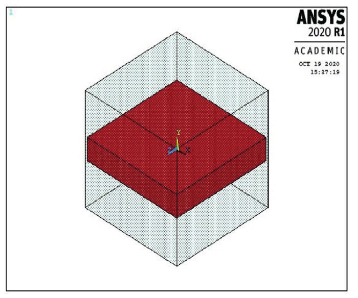
438|Saad and Lengyel
    Period. Polytech. Civ. Eng., 65(2), pp. 437–449, 2021

they may be connectors or pultruded elements as well.                The effect of externally bonded CFRP lamellas on the
The reinforcing materials are usually glued to the ten-           increase of stiffness and capacity of the timber beams was
sion side of the element since they help to increase the          also studied in [11]. The stiffness increase was not recog-
load-bearing capacity and sometimes enhance the bend-             nized and the theoretical ratio of the wood-CFRP modulus
ing stiffness, flexural capacity, and ductility of the tim-       of elasticity to the obtained experimental values was com-
ber-FRP structural elements; as for their application, the        pared and significant differences were found.
reinforcing materials which are usually CFRP or GFRP                 The increase of the carrying capacity of reinforced
are inserted in the timber elements, e.g. Borri et al. [2] pro-   beams varies mainly according to the nature of the element
posed a method to investigate the effect of the CFRP on the       to be strengthened, the wood species, the type of fiber used,
flexural stiffness and capacity of historical timber struc-       the layout of the reinforcement in the element, the volume
tural elements. Four-point-bending experimental anal-             of FRP, and the integrity of the bonding surface between
ysis was also provided to validate the numerical model.           FRP and timber.
They presented an equation that explains the mechanical              The failure mode of timber elements is often due to trans-
behavior of wood elements subjected to tension. A maxi-           verse tension. Timber as known has a natural heterogeneous
mum of 60 % increase in capacity and 30 % in stiffness            character, and the mechanical behavior of timber beams is
were reported. Different ratios of wood Young's modulus           directly affected by the presence of knots, splits, and slope
to CFRP modulus were found which is due to the plasti-            of grains. Two failure modes can be identified when rein-
cization in the zone under compression. Valluzzi et al. [3]       forcing a timber beam with CFRP: the first one is failure
investigated two strengthening techniques for spruce              due to tension which is the dominant one, while the other
wood for already existing structures, the dry connection          occurs when the compression stress limit is reached [5, 12].
with a timber flange at the upper side, and a sheet of CFRP       To predict the ultimate flexural capacity of wood, Liu [13],
at the underside. On timber strengthening, see also [4, 5].       Hasebe and Usuki [14], Patton-Mallory et al. [15] suggested
   The studies on the reinforcement of timber aim to              using the Tsai-Wu strength theory for anisotropic materials.
improve the flexural capacity, ductility, and sometimes the          Defects and faults in the wood are dangerous especially
stiffness of the timber elements, and they, fortunately, yield    when they are found in the tensile zone, and under tension
quite good results in a wide range of engineering prac-           they tend to develop cracks and reduce the capacity and
tice. The results showed that the load-bearing capacity has       stiffness of the beams. Fortunately, these deteriorations
increased by approx. 20–50 % and sometimes higher [2, 6].         can be stopped by using strengthening composite materi-
It was also shown that in most cases stiffness will not be        als for the exposed surface of the beams.
affected at all by the presence of the reinforcements [7, 8]         Experimental and finite element analysis were done
but some researchers revealed an increase of almost 30 %.         in [16] to locally reinforce defected spruce wood beams
The influence of the CFRP and GFRP on the behavior of             by D-shape CFRP strip in the vicinity of the knots (mod-
Pinus Caribea Var. Hondurensis wood species was studied           eled as openings with different diameters) assuming a lin-
in [9]. Fibers were manually attached to timber beams in          ear elastic response for CFRP. Wood was modeled as lin-
the tension zone glued with epoxy resin. Experimental as          ear elastic orthotropic material and tested in the elastic
well as theoretical investigations (with the help of Navier/      range by four-point bending. The general statement is that
Bernoulli model) showed an average increase of 19.175 %           knot usually cause a stress disturbance only in its vicinity
in bending stiffness when the CFRP was applied manu-              (local effect), therefore, it is not economical to reinforce
ally to the timber elements. CFRP fibers with a modulus of        the whole beam and the application of local reinforce-
elasticity 59,000 MPa and tensile strength 1034 MPa were          ments will be beneficial to increase the bending stiffness
used by Tingley and Kent [10], an increase of 21.5 % in the       if we consider a CFRP with at least 16-times higher value
strength and 4.69 % in the stiffness were observed, com-          of Young's modulus in comparison to spruce wood.
pared with results obtained for beams without reinforce-             Many authors proposed finite element models to study the
ment. Analytical, experimental, and FEA studies inves-            behavior of Norway spruce wood members, e.g. [16–19].
tigating the effect of unidirectional CFRP laminate of            Rafsanjani et al. [20] numerically predicted the swelling of
different length and an elastic modulus of 160.7 GPa were         the hierarchical cellular structure of Norway spruce soft-
performed by de Jesus et al. [4]. They showed an increase         wood assuming a transverse anisotropic model. Further-
in elastic stiffness by 23 % and 28 %.                            more, a finite element model to simulate the behavior and
|439
                                                                                                                 Saad and Lengyel
                                                                            Period. Polytech. Civ. Eng., 65(2), pp. 437–449, 2021

to predict the maximum bending capacity of timber Pinus             An example was also presented about a theoretical
sylvestris L. beams subjected to four-point bending consid-      model that was applied to determine the Young's modulus
ering an orthotropic elastoplastic constitutive law in a plane   of Laminated Veneer Lumber (LVL) reinforced by CFRP
stress state was shown by Baño et al. [21]. Mechanical tests     considering that the LVL is homogeneous and the fibers of
were also investigated to validate the model. The mate-          the CFRP are unidirectional [32]. Another example was
rial model in compression was predicted according to Hill        presented by Da Silva Bertolini et al. [33] where the prod-
and as for tension, it was considered linear elastic until       uct inertia EI of the epoxy resin-reinforced timber histori-
rupture. A 2D finite element model in-plane stress state         cal structural element was determined experimentally.
was assumed for Douglas Fir [22]. Transversally isotropic           Moreover, the CFRP elastic properties were predicted
(5 independent material properties for the elastic behav-        using a mathematical approach along with an experimen-
ior) with anisotropic plasticity was assumed to study the        tal analysis for sake of comparison and verification [34].
behavior of Scots pine P. Sylvestris wood with the help of       Unidirectional compressive strength of CFRP were pre-
3D finite element models [23]. With the help of the finite       dicted by applying analytical models [35]. Models and
element method, a bilinear anisotropic hardening model,          equations presented by Hu [36] were also applied to pre-
which is a generalization of the Hill model, was used to         dict the modulus of elasticity of wood-fiberboard.
simulate the behavior of wood [24]. The same model was              As discussed previously, results related to stiffness are
also used by Shih and Lee [25]. Furthermore, Buchanan in         different for each case, and this is mainly due to the use
his work assumed the stress-strain curve for wood, elas-         of different reinforcement types, and the characteristics
tic-plastic behavior for compression, and a linear elastic       of the timber used. The binder material, usually a poly-
for tensile stresses [26].                                       meric resin, does not contribute that much to the increase
   Although wood is highly anisotropic material, the lin-        of the strength properties, but it holds the whole system
ear orthotropic material model can be always applied to          together to make it act as a composite member. The gain in
analyze the behavior of wood in the pure elastic state.          stiffness is influenced by the elastic moduli and allowable
However, linear and nonlinear models along with experi-          stresses of the component materials.
mental investigations have been proposed by many authors            The important fact should be addressed that the effec-
for the evaluation of the complex behavior of carbon rein-       tiveness of the CFRP in terms of its stiffness is signifi-
forced timber beams [27, 28].                                    cantly affected by the method of application (in-situ or pre-
   More studies on the determination of material prop-           fabricated). In former research with the collaboration of the
erties have been proposed. An example was presented              authors, experiments were conducted showing an appar-
to analyze the variations of the wood elastic parameters         ently moderate increase of stiffness [37], which was in cor-
concerning the Young's moduli and shear moduli in the            respondence with several other reported results as shown
LT and LR planes, modeled as a linear elastic orthotro-          above. Based on the test setup, approximately 70 % theo-
pic material in terms of the so-called Euler's angles (λ, ρ)     retical increase of stiffness was expected, highlighting the
introduced by Hermanson, along with some experimental            importance of the applied method of reinforcement and
investigations [29, 30]. A 3D model considering the elas-        suggesting that in situ reinforcement of timber using CFRP
tic-plastic behavior of Norway Spruce (Picea abies) was          is not preferable if the target is to increase the stiffness.
constructed using the (FE) approach with the help of the            The objective of this study is to examine the composite
Generalized Anisotropic Hill Potential Model. The model          structure of a timber beam made of spruce fitted with CFRP
was validated by three-point static bending and compres-         composites to the tension side and to find the material prop-
sion tests to determine the properties of the analyzed mate-     erties of its constituents including the effective stiffness
rial. At first, the material properties were calculated exper-   of the fiber reinforcement. Experiments have been previ-
imentally applying analytical equations provided by the          ously done on Picea abies (Norway spruce) wood species,
British Standard Institute 1957. In the next step, the prop-     which are native to Europe [37]. Regarding the reinforce-
erties were modified by numerically fitting the obtained         ment, they are made of the high quantity of carbon fiber
load deflection curves to the experimental curves. It was        fabric embedded in epoxy resin (matrix), these experiments
assumed that the wood behaves in the linear state as an          aimed to determine the increase of the flexural capacity and
elastic, semi-rigid in tension, and nonlinear ductile behav-     the stiffness of the reinforced timber beams with CFRP,
ior in the state of compression [31].                            thus, to verify the positive effects and the efficiency of the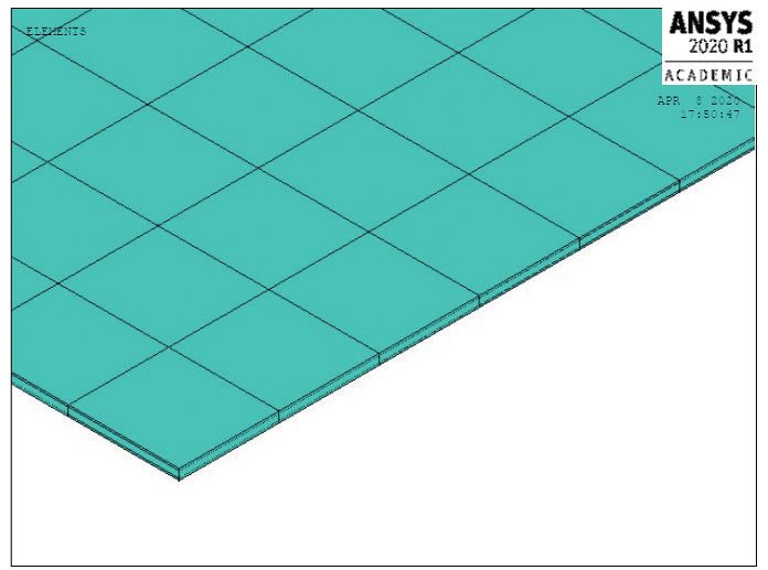
440|Saad and Lengyel
    Period. Polytech. Civ. Eng., 65(2), pp. 437–449, 2021

reinforcement. Using these experimental data, 3D and 2D
finite element models were created using ANSYS coupled
with MATLAB considering elastic and elastic-plastic mate-
rial models to numerically reproduce the measured load-
deflection curves. A series of numerical computations are
aimed to determine the unknown material parameters.

2 Experimental procedure
The experiments in the related study by the authors
involved Norway spruce (Picea abies) fitted with CFRP
fabric. The dimensions of the investigated specimens were
95 mm × 95 mm × 1800 mm and their moisture content at
the time of experimental testing was about 12 % (see [37]
for more details).
   Forty-four member configurations were modeled (see
Table 1) aiming to prove that the type of reinforcement as
                                                                     Fig. 1 Sketch of test arrangement and cross-sections with various
well as wood species, etc. are the most important factors
                                                                                             reinforcement types
which affect significantly on the potential improvement
of the structural behavior and to support the conclusions
with statistical analysis.
   The four-point bending test, see Fig. 1, was used for
each specimen. In the testing European standards were
followed to set the geometric parameters of the beams.
To ensure appropriate measurement, a standard MTS test
authorized device with a capacity of 250 kN was used in
a certified timber structural testing laboratory. Each spec-
imen has a cross-section of 95 mm × 95 mm and 1800 mm
long. The shear span-to-depth ratio was a/h = 6.31, well
within the allowable range of 5–12, where a is the distance
from the support to the nearest point load and h is the
depth of the beam. Specimens were constrained by a sim-
                                                                   Fig. 2 Load-deflection curves for all test specimens. Curves referring
ply supported, pin-roller foundation. The load heads were
                                                                  to test groups S0 (no reinforcement), S1 (single layer), S2 (double layer),
applied at the third points along the length of the beam.
                                                                    and SN (narrow layer) are plotted with thick solid, thin dashed, thin
   The measurement data of load to mid-span deflection                         dash-dot, and thin solid lines, respectively [37]
relationship for all test specimens are shown in Fig. 2. Each
curve comprises linear and nonlinear parts. The loading was          S0, S1, S2, and SN are plotted in thick solid, thin dashed,
also a measured parameter during the experimental analysis        thin dash-dot, and dotted lines, respectively. The reinfor-
with the help of a testing device and a video extensometer,       cement did not lead to significantly increase the stiffness
and digital records have been saved for the analysis.             values of the wood-CFRP system.
                   Table 1 Specimen configuration
                     CFRP fabric
                                                                  3 Numerical modeling
 Test group                                 Number of specimens
                    reinforcement                                 3.1 Model generation
 S0                     none                          8           A 3D FE model was used proposed to perform the analysis
                  1 layer, full width                             and to predict the load-deflection curves of the rectangu-
 S1                                                  20
                    (1.4 mm thick)                                lar solid timber beams strengthened by CFRP under four-
 S2
                 2 layers, full width
                                                      8           point bending as well as to inversely determine the elas-
                   (2.8 mm thick)
                                                                  tic and plastic material properties of wood and the elastic
                1 layer, 50 mm width
 SN
                    (1.4 mm thick)
                                                      8           properties of the CFRP.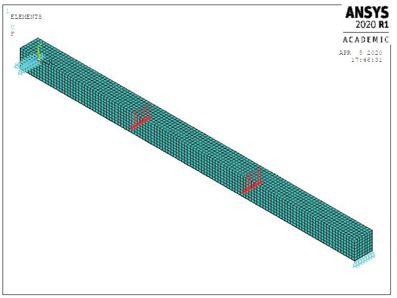
|441
Saad and Lengyel
Period. Polytech. Civ. Eng., 65(2), pp. 437–449, 2021
Fig. 3 Loading, boundary conditions, and element type (a)
Numerical simulations were done using FE available in
ANSYS. Fig. 3 schematically illustrates the loading and
the boundary conditions of the 3D finite element model.
An 8-node solid element with reduced integration
(three translational degrees of freedom per node) was used
to model the timber beams. The FE mesh of the timber
beam consisted of 5880 brick elements type SOLID45.
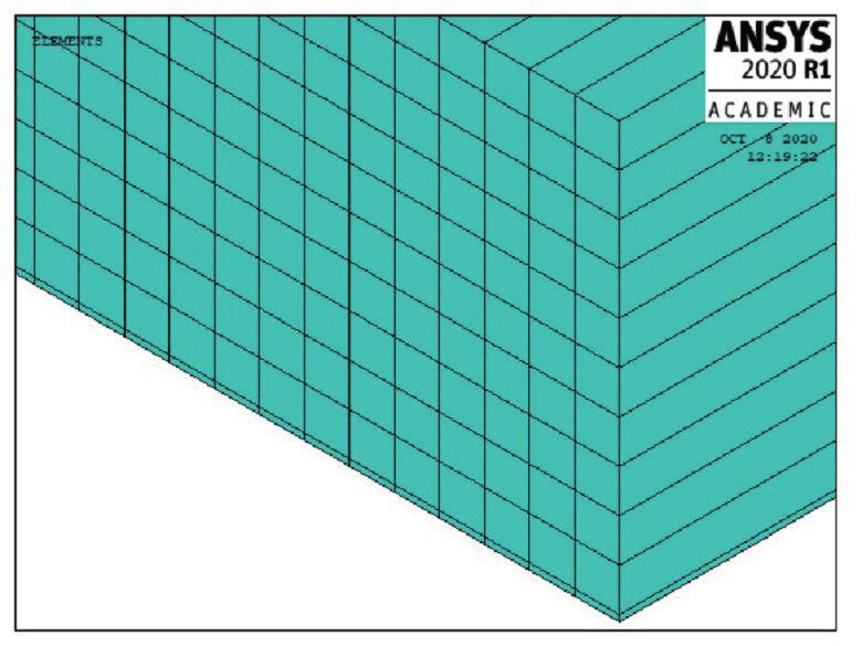
Because the fiber-reinforced polymers are relatively
thin compared to the timber beam, CFRP fabrics were
modeled by a smeared reinforcement layer (consists of
840 REINF265 elements) embedded in a layer of epoxy
represented by 840 SOLID185 elements. Fig. 4 shows the
solid elements of the epoxy (a) and the placement of the
smeared reinforcement layer inside (b). The CFRP ele-
(b)
ments were directly attached to the bottom surface of the
Fig. 4 Epoxy-FRP model: solid elements of the epoxy (a) and the
timber beam, and the interaction between CFRP and tim-
placement of the smeared reinforcement layer inside (b)
ber was considered to be bonded since de-bonding did not
occur in the experiments. Technically, two series of concentrated forces were applied
Furthermore, because all loads and displacements were on nodes along these lines, while boundary conditions
in-plane and there was no variation in geometry, supports, were applied to each node located along the bottom edges
and loads in the transverse direction, two-dimensional to constrain the member and to generate the simply sup-
plane stress assumptions were also applied for simplicity ported system.
and for this purpose 2D finite element models were devel- The proposed material models have been created with
oped and the 8-node plane element (three degrees of free- the help of general-purpose finite element analysis soft-
dom per node) was used to model the timber beams. Fig. 5 ware ANSYS mechanical APDL for defining the mechani-
shows the 3D view of the 2D model (a) and a scaled 3D cal constitutive equations of the wood material and CFRP.
view that highlights the right lowermost series of elements
corresponding to the CFRP (b). The FE mesh of the timber 3.2 Constitutive modeling of wood
beam consisted of 900 elements type PLANE183. CFRP 3.2.1 Linear analysis
fabrics were modeled by shell elements with membrane An elastic orthotropic constitutive relationship for timber
options (SHELL181). elements could be established using the general form of
The loads are transferred to the beam on the top Hooke's law with nine independent material constants as
surface at one and two thirds of the beam longitudinally, σ = Dε, where σ = [σL σR σT τLR τLT τRT]T is the stress vector
and distributed evenly transversely (z direction), see Fig. 3. with indices L, R, and T refers to longitudinal, radial, and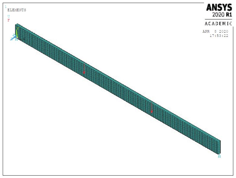
442|Saad and Lengyel
    Period. Polytech. Civ. Eng., 65(2), pp. 437–449, 2021

                                                                                         EL    2 ER     2 EL                 E
                                                                           R = 1 −ν RL
                                                                                    2
                                                                                            −ν TR    −ν TL    − 2ν RLν TRν TL L ,      (1)
                                                                                         ER       ET       ET                ER

                                                                           where Ei (i = L, R, T) are the moduli of elasticity of wood
                                                                           and νij = (i, j = L, R, T) are the Poison's ratios.

                                                                           3.2.2 3D nonlinear analysis: Hill elastic-plastic model
                                                                           The timber beams subjected to tensile loads, present a lin-
                                                                           ear elastic-quasi rigid behavior, and when subjected to com-
                                                                           pression the wood undergoes a linear-elastic behavior and
                                                                           a nonlinear inelastic (perfectly plastic or isotropic harden-
                                                                           ing bilinear) behavior as well. This is why the beam fails
                                                                           for tension in most cases. Therefore, a structural nonlinear
                                  (a)
                                                                           inelastic and rate-independent anisotropic material model,
                                                                           the so-called generalized anisotropic Hill potential model
                                                                           was used to simulate the nonlinear behavior of the tim-
                                                                           ber beams. The generalized Hill plasticity model consid-
                                                                           ers different yield strength in tension than in compression.
                                                                           This material model is used to simulate the anisotropic and
                                                                           asymmetric tension-compression behavior for materials
                                                                           which are characterized by low crystallographic symme-
                                                                           tries such as natural and processed wood products (fabri-
                                                                           cated timber beams) and fiber-matrix composites. In gen-
                                                                           eral cases, the material properties required by Hill model
                                                                           are the compression yield stresses in longitudinal (x), radial
                                                                           (y), and tangential (z) directions (σcx, σcy, and σcz respec-
                                                                           tively) and the corresponding tangent moduli (Etx, Ety, Etz),
                                                                           the tensile yield stresses (σtx, σty, and σtz respectively) and
                                   (b)
                                                                           the corresponding tangent moduli. Furthermore, shear
 Fig. 5 2D plane stress finite element model: 3D view of the 2D model
(top) and a scaled 3D view that highlights the right lowermost series of
                                                                           yield stresses in the material xy, yz, and xz directions and
             elements corresponding to the CFRP (bottom)                   the corresponding tangent moduli.
                                                                              A bilinear anisotropic stress-strain relationship is used
tangential directions, respectively, in the local fiber aligned            to enable the individual components of tension and com-
coordinate system of wood; ε = [ε L ε R εT γ LR γ LT γ RT]T is the         pression yield stresses. The plastic or yield surfaces cor-
strain vector in the same system, and D is the orthotropic                 respond to the Hill model (see Fig. 6), has an anisotropic
material stiffness matrix.                                                 work-hardening rule, and an associated flow rule.
   The orthotropic stiffness matrix D was built with the                      The main assumption for the plasticity is that the
engineering properties of the timber species which will be                 strains are divided into two independent elastic and plastic
determined later. The material properties are independent                  parts as
of loading rates. The effects of the environment such as                   ε = εe + εp .                                               (2)
moisture and temperature on the behavior of timber spe-
cies were not taken into consideration.                                    3.2.3 2D nonlinear analysis
   During the finite element calculation, the eigenvalues                  The in-plane longitudinal components of the total stress
of all the minors matrices of the stiffness matrix should                  are the dominant stresses in case of tension that is why it is
be positive including the determinant of the full matrix to                enough practically to consider a 2D model. Simplification
make sure that the stiffness matrix is positive definite; in               for the variation between the radial, tangential, and longi-
another word, the following relation between the elastic                   tudinal properties was applied and the out of plane prop-
modulus and Poisons ratios should be also positive:                        erties was not considered in the analysis since significant
|443
Saad and Lengyel
Period. Polytech. Civ. Eng., 65(2), pp. 437–449, 2021
3.4 Characteristics of materials
3.4.1 Wood
Norway spruce timber is one of the most well-known spe-
cies in Northern, Central, and Eastern Europe. The wood
material is generally assumed orthotropic, requiring a sig-
nificant number of properties for its complete characteriza-
tion. This wood species has specific characteristics includ-
ing Young's moduli, shear moduli, and Poisson's ratios,
compression yield stresses, tangent modulus and max-
imum tensile strength which are available in some engi-
neering books [39]; therefore, no tests were performed to
find reference values of the mechanical properties of the
modeled timber beams for the analysis.
This study aims to determine the material properties
Fig. 6 Stress-strain relationship for timber beam (Hill anisotropic) [38]
of the timber beams as well as for CFRP under consider-
stresses and strains are not expected in the transverse ation which are capable to produce the same experimen-
direction. Therefore, a linear isotropic material model fol- tally load-deflection curves.
lowed by a bilinear isotropic hardening model was selected Based on sensitivity analysis, which was performed
for wood assuming an elastic-plastic behavior in compres- parametrically by changing the material properties that
sion, and a linear elastic until rupture for tension. do not belong to the longitudinal direction (x direction)
For the 2D plane stress – the stress-strain relationship and evaluate their effects on the overall behavior of wood-
is as follows: CFRP system in terms of the load-deflection curve, it was
found that the overall behavior depends only on the wood
E Eν components related to the longitudinal direction (x-direc-
0
σ 1 −ν 1 −ν tion) and other parameters have negligible effect; therefore,
2 2
x
εx
Eν E the elastic and inelastic properties of wood to be determined
σ y = 0 ε y . (3)
1 −ν 1 −ν 2 are as follows: longitudinal Young's modulus Ex, longitudi-
2
τ
xy E γ xy nal compression yield stress σcx, longitudinal compression
0 0
2 (1 + ν ) tangent modulus Etx, ultimate longitudinal tensile stress σtx.
However, other material properties were set according to
3.3 Constitutive modeling of CFRP literature data [39], the magnitude of these properties are
Reinforcements result in shifting the neutral axis of the very small compared to the longitudinal ones. For Spruce
timber beam downward and this in turn allows greater wood the following ratios are recommended:
plastic deformation in the compression zone; therefore,
EZ
the ductility of the reinforced beams is increased, and the = 0.034 , (4)
EX
failure mechanism is changed. Numerically there are two
methods to model the mechanical behavior of the CFRP: EY
(1) the CFRP material behaves as a linear elastic isotropic = 0.078 , (5)
EX
material, or (2) the CFRP behaves as a linear elastic orth-
otropic material. In bending tests, during which the CFRP G XY
= 0.046 , (6)
is attached along with the grain orientation, the longitudi- EX
nal modulus is the parameter of the highest importance.
An orthotropic model was considered here taken into con- G XZ
= 0.061 , (7)
sideration significantly low stiffness in the plane perpen- EX
dicular to the longitudinal axis. The tensile modulus of
GYZ
elasticity in the fiber direction of the unidirectional CFRP = 0.003 . (8)
material was provided by the manufacturer (Ef = 234 GPa). EX444|Saad and Lengyel
Period. Polytech. Civ. Eng., 65(2), pp. 437–449, 2021
Therefore, the wood modulus of elasticity in the verti- for such parametric analysis; therefore, the inverse analysis
cal direction (Y direction) - Ey for instance can reach up can be performed as follows: (1) with the help of MATLAB
to 1 GPa and this value has a very negligible effect on the macro files are created, (2) ANSYS is called to run in batch
results in terms of deflections and stresses. When multi- mode in order to perform the analysis, (3) collect results
plying its magnitude by 2, the value of the obtained ulti- in form of load-deflection curves, (4) for each specimen,
mate displacement is decreasing by 0.0017 %. simulated load-deflection curves are compared with a sin-
These material properties are first set on a set of aver- gle experimental curve, (5) chose the material properties
age parameter values, which are representative for Norway related to the best fit load-deflection curve.
spruce. The average material properties for spruce wood A 4D grid was analyzed where each of the material
are shown in Table 2. properties to be calculated has their own range for differ-
ent rounds as follows. An average of 4 rounds was needed,
3.4.2 CFRP in the first round an initial grid was chosen where modulus
The only characteristic of the CFRP used to reinforce the of elasticity for wood Ew ran between 7 GPa and 12 GPa in
timber beams, taken from the manufacturer's data sheets steps of 1, wood compression tangent modulus Etx between
is the nominal value of the longitudinal Young's modulus, 0 and 5 GPa in steps of 1 GPa, compression yield stress of
ECFRP see [37]. CFRP fabrics were manually attached to the wood σcx between 25 MPa and 50 MPa in steps of 1 MPa,
tension side of the timber beams to allow greater plastic FRP modulus of elasticity between 20 GPa and 240 GPa
deformation in the compression zone; therefore, to increase in step of 20 GPa. 11232 input files were generated with
the ductility of the reinforced beams. the help of MATLAB and the obtained numerical load-
The law of mixture states that Ecomp = Vf Ef + Ve Ee, deflection curves were compared with a single experimen-
where V denotes the volume fraction and indices f and e tal one. In the next rounds, the discrete optimum of the
refer to the fiber and the epoxy, respectively. Considering error function in the grid is located. Assuming that the
that 99 % of composite is fibers (as provided by the man- optimum is in the neighborhood of the discrete optimum,
ufacturer), therefore Ecomp = 231 GPa. Fibers have a high a finer grid is created around it and the analysis is rerun
modulus within fiber direction but if the force is not on that grid.
applied within fiber direction, this modulus is dramati- The indicator of fitting is the error function, that is, the
cally decreased. Yet, only fibers within the load direction integral of the square of the difference between the simu-
show the effectiveness of the modulus. lated and the measured curves:
The only material property of the CFRP that is unknown Fmax
is the longitudinal tensile Young's modulus ECFRP (denoted
f err = ∫ 0
( es − em )2 dF , (9)
by Er later). where Fmax is the ultimate load of the specimen, es and em
refer to the simulated and the measured displacement data,
4 Principle of inverse analysis respectively. The measurements are given as discrete
The inverse analysis in our study is the process of recal- points, and the simulated function is also evaluated at dis-
culating the load-deflection curves from a set of assigned crete points. Between points piecewise linear functions are
material properties for wood and CFRP that produced them. assumed hence the integration can be formulated easily.
It is named an inverse analysis since it starts with the The inverse analysis is considered "inverse" to the prob-
results, in other words, with the material properties that we lem which relates the model material properties to the
are looking for. This kind of analysis is one of the most results (load-deflection curve). The analysis requires start-
important analyses in science and mathematics because they ing with an assumed stress-strain diagram for each spec-
tell us about parameters that we cannot directly observe. imen and find out; after the analysis, its load-deflection
Combining ANSYS with MATLAB creates a powerful tool curve which should be the same as found in the experiment.
Table 2 Spruce material properties [39]
5 Results and discussion
EL = 9900 MPa μ LR = 0.39 GTL = 610 MPa 5.1 Load-deflection curve
ER = 730 MPa μ LT = 0.49 GRT = 22 MPa Initially the load-deflection curve showed a linear behav-
ET = 410 MPa μRT = 0.64 GLR = 500 MPa ior until the wood starts to yield in compression. After
Average compression yield yielding the beams showed a nonlinear behavior, with
σcL = 30 MPa
strength parallel to the grain
reduced stiffness up to failure.Saad and Lengyel
Period. Polytech. Civ. Eng., 65(2), pp. 437–449, 2021
|445
The quasi-static loading technique is not only to predict S1 No. 12
30
accurate failure capacities but also to attempt to model
EXP
the member behavior during a loading event. Therefore, 3D FEM
25
with the finite element results, load-deflection curves
were plotted to compare the behavior of the model with
20
the load-deflection curves provided by the previously done
Load [KN]
experiments which in turn will correspond to the mate-
15
rial properties of wood-CFRP materials. Figs. 7 to 10 are
plots of the load-deflection curves obtained from the 3D
10
finite element analyses along with the load-deflection data
obtained from the entire sample of specimens tested for
5
each respective case.
Fig. 7 is the plot of a selected specimen in the control
0
group (S0) with no reinforcements. The dominant failure 0 5 10 15 20 25 30 35 40 45 50
Deflection [mm]
mode of the model was the tensile failure. Comparing the
failure load of the control model to the models where tim- Fig. 8 Single layer reinforced beam S1 (specimen No. 12)
ber beams are reinforced indicates an increase in flexural
capacity. In each case containing reinforcements, failure 35
S2 No. 5
always initiated in timber. The non-linear effects were EXP
included in all the models. 30 3D FEM
Figs. 8–10 are load-deflection curves for selected cases
25
in groups S1, S2, and SN, respectively. All cases were mod-
eled using the load-stepping technique to model the non- 20
Load [KN]
linear behavior. As can be seen in the figures, the 3D FEA
results fall well within the spread of the experimental data. 15
The failures always initiated at the tension zone of the
timber, which is the location where the material cannot 10
undergo any plastic deformation. However, this can lead
5
in most cases to lose the capacity in compression which in
turn leads to obtain a low ductile member. Furthermore, 0
0 10 20 30 40 50 60
Fig. 11 highlights the differences between the 3D, 2D Deflection [mm]
finite element models, and the experimental load-deflec-
Fig. 9 Double-layer reinforced beam S2 (specimen No. 5)
tion curves for a single reinforced beam.
S0 No. 6 SN No. 5
35 40
EXP EXP
3D FEM 35
30 3D FEM
30
25
25
Load [KN]
20
Load [KN]
20
15
15
10
10
5 5
0 0
0 10 20 30 40 50 60 0 10 20 30 40 50 60 70
Deflection [mm] Deflection [mm]
Fig. 7 Non reinforced beam S0 (specimen No. 6) Fig. 10 Half-layer reinforced beam SN (specimen No. 5)446|Saad and Lengyel
Period. Polytech. Civ. Eng., 65(2), pp. 437–449, 2021
35
S1 No. 18
3D Hill anisotropic material model can model both ten-
EXP
sion and compression behavior in wood. Therefore, the
30 3D FEM bilinear stress-strain relationship in compression espe-
2D FEM
25
cially with perfect plasticity can capture the trend of the
load-deflection curves in most cases. The average modu-
20 lus of elasticity of the wood material is 9369.831 N/mm 2
Load [KN]
with an average relative standard deviation of 20.04 %.
15
The average compression yield stress is 33.22 N/mm 2
10 with a relative standard deviation of 18.66 %. As for
the reinforcements, the average moduli of elasticity are
5 59710 N/mm 2 with large relative standard deviations.
The 2D finite element model, which considers both
0
0 5 10 15 20 25 30 35 40 45 elastic tensions, and inelastic compression (bilinear hard-
Deflection [mm]
ening) gives also similar results (see Table 3), as apparent
Fig. 11 3D, 2D, and experimental load-deflection curves (S1 No. 18)
through the examples shown in the previous subsection.
5.2 Material properties Large immediate loss of load-bearing capacity reflected
The selected specimens shown in the previous subsection by the significant drop of the slope of the load-deflection
provide a good sample of the general behavior. Table 3 curve is found which is due to rupture in the tension zone.
summarizes the statistics of the results for both the 2D This excessive behavior was not exhibited by any of the
and the 3D finite element models. The numbers in the table test specimens, except just before the collapse. Hence,
are the mean values of the parameters in each group with the non-linearity of the structure is not only due to the
corresponding standard deviations shown in parentheses. tensile rupture.
Table 3 Mean values of optimal material parameters (wood modulus EW = EL , reinforcement modulus Er, wood compression yield stress σcx = σcL , the
wood tensile maximum stress σ tx = σ tL , and wood tangent modulus Etx) in all specimen groups for all models (3D and 2D). Standard deviations are
given in parentheses
3D model 2D model % of
Group Type Material property (MPa)
(Hill) (BISO) difference
Longitudinal Young's modulus EW 10388.75 (1275.46) 9842.375 (1066.54) 5.55
No reinforcement Longitudinal compression yield stress σcx 30.714 (7.88) 30.227 (8.35) 1.61
Wood
(S0) Longitudinal compression tangent modulus Etx 1585.71 (1989.49) 1628.85 (2548.50) 2.72
Ultimate longitudinal tensile stress σtx 54.95 (20.77) 54.53 (20.29) 0.77
Longitudinal Young's modulus EW 8883.7 (1614.34) 8502.7 (1762.15) 4.48
Longitudinal compression yield stress σcx 35.203 (6.53) 34.873 (6.66) 0.946
Reinforced with Wood
Longitudinal compression tangent modulus Etx 547.31 (1477.87) 609.63 (1520.96) 11.38
1 layer (S1)
Ultimate longitudinal tensile stress σtx 46.35 (13.01) 47.76 (15.22) 3.04
CFRP Fiber's modulus of elasticity Er 74717.2 (42.32) 74713 (41.56) 5.62e-3
Longitudinal Young's modulus EW 8431.25 (1486.4) 8260 (1577.62) 2.07
Longitudinal compression yield stress σcx 32.854 (3.13) 33.1125 (2.89) 0.786
Reinforced with Wood
Longitudinal compression tangent modulus Etx 326.5 (922.64) 375.25 (1060) 14.93
2 layers (S2)
Ultimate longitudinal tensile stress σtx 44.93 (11.85) 48.08 (13.75) 7.01
CFRP Fiber's modulus of elasticity Er 40846 (21.2) 41125 (19.92) 0.68
Longitudinal Young's modulus EW 9900.625 (1497.38) 9533.375 (1443.82) 3.85
Longitudinal compression yield stress σcx 34.13 (7.15) 33.71 (6.72) 1.24
Reinforced with Wood
Longitudinal compression tangent modulus Etx 1150 (1253.69) 1171.25 (1257.94) 1.84
a half layer (SN)
Ultimate longitudinal tensile stress σtx 53.63 (10.97) 53.75 (10.65) 0.22
CFRP Fiber's modulus of elasticity Er 63591.5 (33.46) 62975.25 (32.68) 0.97|447
Saad and Lengyel
Period. Polytech. Civ. Eng., 65(2), pp. 437–449, 2021
5.3 Discussion The CFRP materials applied in the tension zone of the
Important conclusions are obtained with the help of the timber beams help to reduce the tensile stresses of the
3D and 2D numerical models applied for the wood-CFRP wood-CFRP system which in turn helps in increasing
materials. Materials tested in the experimental analysis the ductility of the latter as well as achieving higher ulti-
were obtained from the same origin possessing similar mate load. Yet, an important difference between the rein-
properties and following the same application technique. forced and unreinforced beams implies that the plastic
Properties of wood obtained with the help of the numerical compression capacity of the wood is utilized to a higher
simulations are in the range characteristic of this species degree before failure.
with given standard deviations. The modulus of the reinforcement material obtained
For the specimen groups with different reinforcement for all of the specimens is below the nominal theoret-
set no observable significant differences. 3D Hill aniso- ical value of the carbon fiber provided by the manufac-
tropic and 2D models had practically identical results in turer (i.e. 234 kN/mm 2). The in-situ preparation method
terms of the elastic and plastic mechanical properties. of CFRP fabric is one of the most significant reasons.
The finite element analysis was perfectly able to follow The glue was spread on the surface of the tension zone of
and capture the non-linearity in compression of wood the timber beams with a roller so the matrix and the bond
applying potential hardening beyond the elastic limit until to the timber can be obtained simultaneously. This method
failure. Nevertheless, the non-linearity in the wood mate- can provide a perfect bond between fibers and timber and
rial is observed to be different in terms of the tangent efficiently applicable to be applied in arbitrary positions.
modulus. The perfectly plastic behavior in the compres- Yet, the sensitivity of the extremely thin fibers to any
sion zone of the wood where the tangent modulus is zero action such as bending and axial tension is an indicator
was in most cases a good adjustment for both models to of the disadvantages of this method since the fibers in the
capture the curvature of the load-defection diagram and lamellae may undergo damage to some degree. Geometric
to obtain a significantly better fit. The tangent moduli are imperfections of the fibers (such as waviness) are also
somewhat scattered in a range covering both positive and bound to be introduced, further reducing the modulus
null values. Therefore, the compression behavior is chang- of elasticity. Since the thickness of the fabric is greater
ing from an individual specimen to another. than usual and the consistency of the epoxy is high, much
Although the wood material in tension was modeled as strength is required to make the epoxy penetrate the fab-
a linear elastic, the rupture should be modeled in a more ric, so its effect is significant. The elastic modulus is also
refined way since tension rupture occurred in some of the found to be smaller in case of double reinforcement due to
specimens during the loading process causing a gradual the large induced disturbance during the application of the
micro and macro local failures at different locations, that epoxy which requires a larger pressure. The low increase
is because wood is a natural material and wood grains of stiffness has been reported also in other researches.
have different strength naturally. This effect can be cap- A considerable increase in capacity can be achieved how-
tured considering wood models that should be able to ever with a negligible increase of stiffness. H. Alhayek
attribute different properties for different parts of the and Svecova [40] recommended not to consider fiber
cross-section along with an appropriate parameterization. reinforcement to enhance stiffness. Regarding the low
However, the full progressive failure in most specimens increase in stiffness, see also other papers, e.g. [4, 9, 11].
occurred after localized rupture failures in the tension The values of the elastic modulus of reinforcement
zone indicating the effects of the weak points on the over- obtained in this study agreed perfectly with the increased
all behavior of the timber material. Defects and knots in stiffness obtained from the measurements. If the analysis
the timber material are among the most significant weak relies on the assumed nominal value of the elastic modu-
points that may affect the reliability of the specimens. lus of the fiber by the provider; then over 65 % increase in
The measured ultimate capacity of each specimen reflects stiffness should be reported by performing a simple calcu-
these variations. The compression capacity in the timber lation of the strength of materials. The imperfections and
material is not fully utilized due to the early tensile fail- waviness of the fibers can be captured with the help of a
ure, which indicates that the ductility of the beams var- detailed finite element model which will be a continuation
ies in a range depending on when the rupture took place. of this research.448|Saad and Lengyel
Period. Polytech. Civ. Eng., 65(2), pp. 437–449, 2021
6 Conclusions species being referred to. The calculations have indicated
In this research the material properties of CFRP-wood that the because of geometrical defects and potential dam-
composite were inversely determined with the help of age are the main reasons why the effective stiffness of the
numerical parametric technique along with the load- fiber material is decreased contrasted with the hypothet-
deflection curves. The viability of the technique has ical qualities. The strategy has given significant infor-
been represented through a progression of information mation on the physical abilities of the present reinforcing
acquired from four-point bending tests led in past research procedure.
on Spruce timber strengthened with CFRP fabrics. The load-deflection data along with the inverse determi-
The technique scans for the ideal arrangement of model nation of material properties helped in acquiring import-
constants that limits the distinction between the simulated ant information on the global behavior of full-size beams.
and the measured load-deflection curves. The optimal
material properties were found by applying two distinc- Acknowledgments
tive numerical models for wood and two models for rein- The presented work was conducted with the financial sup-
forcement separately for every specimen. The obtained port of the K119440 project of the Hungarian National
properties of wood are in the average range explicit to the Research, Development, and Innovation Office.
References
[1] Theakston, F. H. "A feasibility study for strengthening timber beams [9] Fiorelli, J., Dias, A. A. "Analysis of the strength and stiffness of tim-
with fiberglass", Canadian Agricultural Engineering, 7(1), pp. ber beams reinforced with carbon fiber and glass fiber", Materials
17–19, 1965. Research, 6(2), pp. 193–202, 2003.
[2] Borri, A., Corradi, M., Grazini, A. "A method for flexural reinforce- https://doi.org/10.1590/s1516-14392003000200014
ment of old wood beams with CFRP materials", Composites Part B: [10] Kent, S., Tingley, D. "Structural Evaluation of Fiber Reinforced
Engineering, 36(2), pp. 143–153, 2005. Hollow Wood Beams", In: Innovative Wooden Structures and
https://doi.org/10.1016/j.compositesb.2004.04.013 Bridges, IABSE Conference Report 85, Lahti, Finland, 2001, pp.
[3] Valluzzi, M. R., Garbin, E. Modena, C. "Flexural strengthening of 367–372.
timber beams by traditional and innovative techniques", Journal of https://doi.org/10.2749/222137801796348845
Building Appraisal, 3(2), pp. 125–143, 2007. [11] Neubauerová, P. "Timber beams strengthened by carbon–fiber rein-
https://doi.org/10.1057/palgrave.jba.2950071 forced lamellas", Procedia Engineering, 40, pp. 292–297, 2012.
[4] de Jesus, A. M. P., Pinto, J. M. T., Morais, J. J. L. "Analysis of solid https://doi.org/10.1016/j.proeng.2012.07.097
wood beams strengthened with CFRP laminates of distinct lengths", [12] Borri, A., Corradi, M., Vignoli, A. "New materials for strengthening
Construction and Building Materials, 35, pp. 817–828, 2012. and seismic upgrading interventions", In: International Workshop
https://doi.org/10.1016/j.conbuildmat.2012.04.124 Ariadne, Prague, Czech Republic, 2002, pp. 22–28.
[5] Corradi, M., Maheri, A., Osofero, A. I. "Design of Reinforced and [13] Liu, J. Y. "Evaluation of the Tensor Polynomial Strength Theory for
Unreinforced Timber Beams subject to Uncertainties", In: Topping, Wood", Journal of Composite Materials, 18(3), pp. 216–226, 1984.
B. H. V., Iványi, P. (eds.) Proceedings of the Twelfth International https://doi.org/10.1177/002199838401800302
Conference on Computational Structures Technology, Civil-Comp [14] Hasebe, K., Usuki, S. "Application of Orthotropic Failure Criterion
Press, Stirlingshire, UK, Paper 134, 2014. to Wood, Journal of Engineering Mechanics", 115(4), pp. 867–872,
https://doi.org/10.4203/ccp.106.134 1989.
[6] Gentile, C., Svecova, D., Rizkalla, S. H. "Timber Beams https://doi.org/10.1061/(asce)0733-9399(1989)115:4(867)
Strengthened with GFRP Bars: Development and Applications", [15] Patton-Mallory, M., Pellicane, P. J., Smith, F. W. "Modeling Bolted
Journal of Composites for Construction, 6(1), pp. 11–20, 2002. Connections in Wood, Journal of Structural Engineering", 123(8),
https://doi.org/10.1061/(asce)1090-0268(2002)6:1(11) pp. 1054–1062, 1997.
[7] Amy, K., Svecova, D. "Strengthening of dapped timber beams using https://doi.org/10.1061/(asce)0733-9445(1997)123:8(1054)
glass fibre reinforced polymer bars", Canadian Journal of Civil [16] Burawska, I., Mohammadi, A. H., Widmann, R., Motavalli, M.
Engineering, 31(6), pp. 943–955, 2004. "Local reinforcement of timber beams using D-shape CFRP strip",
https://doi.org/10.1139/l04-063 presented at SMAR 2015 – Third Conference on Smart Monitoring,
[8] de la Rosa García, P., Escamilla, A. C., García, M. N. G. "Bending Antalya, Turkey, Sept, 7–9, 2015.
reinforcement of timber beams with composite carbon fiber and [17] Hu, M. "Studies of the fibre direction and local bending stiff-
basalt fiber materials", Composites Part B: Engineering, 55, pp. ness of Norway spruce timber: for application on machine
528–536, 2013. strength grading", Doctoral thesis, Linnaeus University, 2018.
https://doi.org/10.1016/j.compositesb.2013.07.016 [online] Available at: http://lnu.diva-portal.org/smash/record.
jsf?pid=diva2%3A1172057&dswid=9881|449
Saad and Lengyel
Period. Polytech. Civ. Eng., 65(2), pp. 437–449, 2021
[18] Briggert, A., Hu, M., Olsson, A., Oscarsson, J. "Tracheid effect [31] Milch, J., Tippner, J., Sebera, V., Brabec, M. "Determination of
scanning and evaluation of in-plane and out-of-plane fibre direc- the elasto-plastic material characteristics of Norway spruce and
tion in Norway spruce using", Wood and Fiber Science, 50(4), pp. European beech wood by experimental and numerical analyses",
411–429, 2018. Holzforschung, 70(11), pp. 1081–1092, 2016.
https://doi.org/10.22382/wfs-2018-053 https://doi.org/10.1515/hf-2015-0267
[19] Foley, C. "A three-dimensional paradigm of fiber orientation in tim- [32] Wei, P., Wang, B. J., Zhou, D., Dai, C., Wang, Q., Huang, S.
ber", Wood Science and Technology, 35(5), pp. 453–465, 2001. "Mechanical Properties of Poplar Laminated Veneer Lumber
https://doi.org/10.1007/s002260100112 Modified by Carbon Fiber Reinforced Polymer", BioResources,
[20] Rafsanjani, A., Lanvermann, C., Niemz, P., Carmeliet, J., Derome, D. 8(4), pp. 4883–1898, 2013.
"Multiscale analysis of free swelling of Norway spruce", Composites https://doi.org/10.15376/biores.8.4.4883-4898
Part A: Applied Science and Manufacturing, 54, pp. 70–78, 2013. [33] Da Silva Bertolini, M., de Macedo, L. B., de Almeida, D. H.,
https://doi.org/10.1016/j.compositesa.2013.07.005 Icimoto, F. H., Lahr, F. A. R. "Restoration of Structural Timber
[21] Baño, V., Arriaga, F., Soilán, A., Guaita, M. "Prediction of bending Elements Using Epoxy Resin: Analysis of Mechanical Properties",
load capacity of timber beams using a finite element method simula- Advanced Materials Research, 778, pp. 582–587, 2013.
tion of knots and grain deviation", Biosystems Engineering, 109(4), https://doi.org/10.4028/www.scientific.net/amr.778.582
pp. 241–249, 2011. [34] Rahmani, H., Najaf, S. H. M., Ashori, A., Golriz, M. "Elastic
https://doi.org/10.1016/j.biosystemseng.2011.05.008 Properties of Carbon Fibre-Reinforced Epoxy Composites",
[22] Williams, J. M., Fridley, K. J., Cofer, W. F., Falk, R. H. "Failure Polymers and Polymer Composites, 23(7), pp. 475–482, 2015.
modeling of sawn lumber with a fastener hole", Finite Elements in https://doi.org/10.1177/096739111502300706
Analysis and Design, 36(1), pp. 83–98, 2000. [35] Leopold, C., Harder, S., Philipkowski, T., Liebig, W. V., Fiedler, B.
https://doi.org/10.1016/s0168-874x(00)00010-x "Comparison of Analytical Approaches Predicting the Compressive
[23] Guindos, P., Guaita, M. "A three-dimensional wood material model Strength of Fibre Reinforced Polymers", Materials, 11(12), Article
to simulate the behavior of wood with any type of knot at the mac- number: 2517, 2018.
ro-scale", Wood Science and Technology, 47(3), pp. 585–599, 2013. https://doi.org/10.3390/ma11122517
https://doi.org/10.1007/s00226-012-0517-4 [36] Hu, Y. C. "Predicting Modulus of Elasticity for Wood-Based
[24] Valliappan, S., Boonlaulohr, P., Lee, I. K. "Non‐linear analysis for Composites", Materials Science Forum, 575, pp. 1106–1110, 2008.
anisotropic materials", International Journal for Numerical Methods https://doi.org/10.4028/www.scientific.net/msf.575-578.1106
in Engineering, 10(3), pp. 597–606, 1976. [37] Andor, K., Lengyel, A., Polgar, R., Fodor, T, Karácsonyi, Z.
https://doi.org/10.1002/nme.1620100309 "Experimental and statistical ´analysis of spruce timber beams rein-
[25] Shih, C. F., Lee, D. "Further Developments in Anisotropic Plasticity", forced with CFRP fabric", Construction and Building Materials, 99,
Journal of Engineering Materials and Technology, 100(3), pp. 294– pp. 200–207, 2015.
302, 1978. https://doi.org/10.1016/j.conbuildmat.2015.09.026
https://doi.org/10.1115/1.3443493 [38] Ansys, Inc. "ANSYS advanced analysis techniques guide", ANSYS,
[26] Bazan, I. M. M. "Ultimate bending strength of timber beams", Canonsburg, PA, USA, 2001.
Doctoral thesis, Technical University of Nova Scotia, 1980. [39] Szalai, J. "A faanyag és faalapú anyagok anizotróp rugalmasság-és
[27] Raftery, G. M., Harte, A. M. "Nonlinear numerical modelling szilárdságtana. I. rész. A mechanikai tulajdonságok anizotrópiája"
of FRP reinforced glued laminated timber", Composites Part B: (The anisotropic flexibility and strength theory of the tree and
Engineering, 52, pp. 40–50, 2013. tree-based materials, Part I. Anisotropy of mechanical proper-
https://doi.org/10.1016/j.compositesb.2013.03.038 ties), Erdészeti és Faipari Egyetem, Sopron, Hungary, 1994. (in
[28] Khelifa, M., Vila Loperena, N., Bleron, L., Khennane, A. "Analysis Hungarian)
of CFRP-strengthened timber beams", Journal of Adhesion Science [40] Alhayek, H., Svecova, D. "Flexural Stiffness and Strength of GFRP-
and Technology, 28(1), pp. 1–14, 2014. Reinforced Timber Beams", Journal of Composites for Construction,
https://doi.org/10.1080/01694243.2013.815096 16, pp. 245–252, 2012.
[29] Mascia N. T., Lahr, F. A. R. "Remarks on orthotropic elastic models https://doi.org/10.1061/(asce)cc.1943-5614.0000261
applied to wood", Materials Research, 9(3), pp. 301–310, 2006.
https://doi.org/10.1590/s1516-14392006000300010
[30] Hermanson, J. C. "The triaxial behavior of redwood using a new
confined compression device", University of Wisconsin–Madison,
Madison, WI, USA, 1997.You can also read