Io 4K Plus - Installation and Operation Manual - Capture, Display, Convert - AJA Video
←
→
Page content transcription
If your browser does not render page correctly, please read the page content below
                                 Io 4K Plus
                              Capture, Display, Convert

            Installation and Operation Manual

Version 15.1
Published February 28, 2019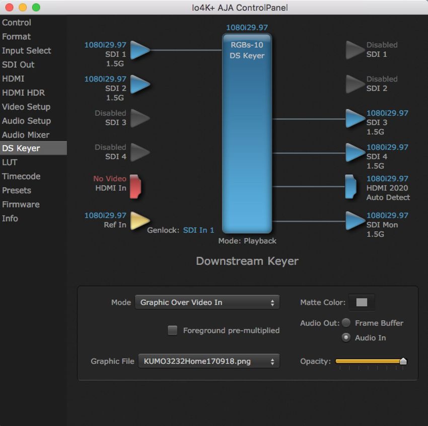
    Notices
                   Trademarks
                        AJA® and Because it matters.® are registered trademarks of AJA Video Systems, Inc.
                        for use with most AJA products. AJA™ is a trademark of AJA Video Systems, Inc. for
                        use with recorder, router, software and camera products. Because it matters.™ is a
                        trademark of AJA Video Systems, Inc. for use with camera products.
                        CION®, Corvid Ultra®, lo®, Ki Pro®, KONA®, KUMO®, ROI® and T-Tap® are registered
                        trademarks of AJA Video Systems, Inc.
                        AJA Control Room™, KiStor™, Science of the Beautiful™, TruScale™, TruZoom™,
                        V2Analog™ and V2Digital™ are trademarks of AJA Video Systems, Inc.
                        All other trademarks are the property of their respective owners.

                   Copyright
                        Copyright © 2019 AJA Video Systems, Inc. All rights reserved. All information in
                        this manual is subject to change without notice. No part of the document may be
                        reproduced or transmitted in any form, or by any means, electronic or mechanical,
                        including photocopying or recording, without the express written permission of AJA
                        Video Systems, Inc.

                   Contacting AJA Support
                        When calling for support, have all information at hand prior to calling. To contact AJA
                        for sales or support, use any of the following methods:

                         Telephone           +1.530.271.3190
                         FAX                 +1.530.271.3140
                         Web                 https://www.aja.com
                         Support Email       support@aja.com
                         Sales Email         sales@aja.com

Io 4K Plus Capture, Display, Convert v15.1                         2                                              www.aja.com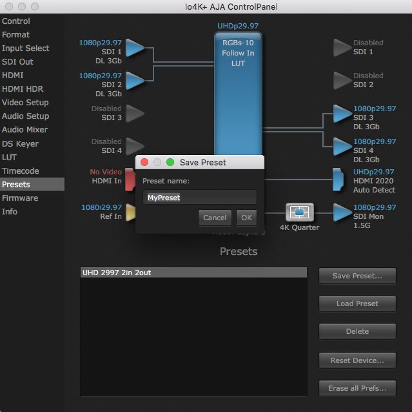
    Contents
                             Notices  .  .  .  .  .  .  .  .  .  .  .  .  .  .  .  .  .  .  .  .  .  .  .  .  .  .  .  .  .  .  .  .  .  .  .  .  .  .  2
                                    Trademarks .  .  .  .  .  .  .  .  .  .  .  .  .  .  .  .  .  .  .  .  .  .  .  .  .  .  .  .  .  .  .  .  .  .  .  .  .  .  .  .  .  .  .  2
                                    Copyright  .  .  .  .  .  .  .  .  .  .  .  .  .  .  .  .  .  .  .  .  .  .  .  .  .  .  .  .  .  .  .  .  .  .  .  .  .  .  .  .  .  .  .  .  2
                                    Contacting AJA Support .  .  .  .  .  .  .  .  .  .  .  .  .  .  .  .  .  .  .  .  .  .  .  .  .  .  .  .  .  .  .  .  .  .  .  2

                             Chapter 1 – Introduction .  .  .  .  .  .  .  .  .  .  .  .  .  .  .  .  .  .  .  .  .  .  .  .  .  .  .  5
                                    Overview .  .  .  .  .  .  .  .  .  .  .  .  .  .  .  .  .  .  .  .  .  .  .  .  .  .  .  .  .  .  .  .  .  .  .  .  .  .  .  .  .  .  .  .  .    5
                                       Features  .  .  .  .  .  .  .  .  .  .  .  .  .  .  .  .  .  .  .  .  .  .  .  .  .  .  .  .  .  .  .  .  .  .  .  .  .  .  .  .  .  .  .  .   5
                                       High Quality Down Conversion . . . . . . . . . . . . . . . . . . . . . . . . . . . . .                                                         6
                                       Io 4K Plus Audio  .  .  .  .  .  .  .  .  .  .  .  .  .  .  .  .  .  .  .  .  .  .  .  .  .  .  .  .  .  .  .  .  .  .  .  .  .  .  .          6
                                       AJA Software & Utilities  .  .  .  .  .  .  .  .  .  .  .  .  .  .  .  .  .  .  .  .  .  .  .  .  .  .  .  .  .  .  .  .  .  .                 6
                                    System Requirements .  .  .  .  .  .  .  .  .  .  .  .  .  .  .  .  .  .  .  .  .  .  .  .  .  .  .  .  .  .  .  .  .  .  .  .  .                 7
                                    What’s In The Box?  .  .  .  .  .  .  .  .  .  .  .  .  .  .  .  .  .  .  .  .  .  .  .  .  .  .  .  .  .  .  .  .  .  .  .  .  .  .  .           7
                                    In This Manual  .  .  .  .  .  .  .  .  .  .  .  .  .  .  .  .  .  .  .  .  .  .  .  .  .  .  .  .  .  .  .  .  .  .  .  .  .  .  .  .  .         7

                             Chapter 2 – Installation .  .  .  .  .  .  .  .  .  .  .  .  .  .  .  .  .  .  .  .  .  .  .  .  .  .  .  .  9
                                    Installation Overview .  .  .  .  .  .  .  .  .  .  .  .  .  .  .  .  .  .  .  .  .  .  .  .  .  .  .  .  .  .  .  .  .  .  .  .  .  9
                                       System Test Application .  .  .  .  .  .  .  .  .  .  .  .  .  .  .  .  .  .  .  .  .  .  .  .  .  .  .  .  .  .  .  .  .  . 9
                                       Cable Connections . . . . . . . . . . . . . . . . . . . . . . . . . . . . . . . . . . . . 10
                                       Connector Descriptions .  .  .  .  .  .  .  .  .  .  .  .  .  .  .  .  .  .  .  .  .  .  .  .  .  .  .  .  .  .  .  .  . 10
                                    Installing Software  .  .  .  .  .  .  .  .  .  .  .  .  .  .  .  .  .  .  .  .  .  .  .  .  .  .  .  .  .  .  .  .  .  .  .  .  .  . 11

                             Chapter 3 – Io 4K Plus Operation .  .  .  .  .  .  .  .  .  .  .  .  .  .  .  .  .  .  .  .  .  13
                                    Front Panel Operation .  .  .  .  .  .  .  .  .  .  .  .  .  .  .  .  .  .  .  .  .  .  .  .  .  .  .  .  .  .  .  .  .  .  .  .13
                                       Monitor Output and Gain Control .  .  .  .  .  .  .  .  .  .  .  .  .  .  .  .  .  .  .  .  .  .  .  .  .  .  .13
                                       Audio Level Meters .  .  .  .  .  .  .  .  .  .  .  .  .  .  .  .  .  .  .  .  .  .  .  .  .  .  .  .  .  .  .  .  .  .  .  . 13
                                       Power LED .  .  .  .  .  .  .  .  .  .  .  .  .  .  .  .  .  .  .  .  .  .  .  .  .  .  .  .  .  .  .  .  .  .  .  .  .  .  .  .  .  .14
                                    AJA Control Panel Overview  .  .  .  .  .  .  .  .  .  .  .  .  .  .  .  .  .  .  .  .  .  .  .  .  .  .  .  .  .  .  .  .14
                                       AJA Control Panel User Interface .  .  .  .  .  .  .  .  .  .  .  .  .  .  .  .  .  .  .  .  .  .  .  .  .  .  .  .14
                                       Controlling Application . . . . . . . . . . . . . . . . . . . . . . . . . . . . . . . . . 16
                                       Presets .  .  .  .  .  .  .  .  .  .  .  .  .  .  .  .  .  .  .  .  .  .  .  .  .  .  .  .  .  .  .  .  .  .  .  .  .  .  .  .  .  .  .  . 16
                                       Default Preferences  .  .  .  .  .  .  .  .  .  .  .  .  .  .  .  .  .  .  .  .  .  .  .  .  .  .  .  .  .  .  .  .  .  .  .  .16
                                       Function Screens .  .  .  .  .  .  .  .  .  .  .  .  .  .  .  .  .  .  .  .  .  .  .  .  .  .  .  .  .  .  .  .  .  .  .  .  .  .18
                                    Using Io 4K Plus for UltraHD/4K  .  .  .  .  .  .  .  .  .  .  .  .  .  .  .  .  .  .  .  .  .  .  .  .  .  .  .  .  .  .18
                                       4K/UltraHD Transport Modes .  .  .  .  .  .  .  .  .  .  .  .  .  .  .  .  .  .  .  .  .  .  .  .  .  .  .  .  .  .18
                                    Io 4K Plus Audio Monitoring .  .  .  .  .  .  .  .  .  .  .  .  .  .  .  .  .  .  .  .  .  .  .  .  .  .  .  .  .  .  .  . 20
                                    AJA Control Panel Function Screens  .  .  .  .  .  .  .  .  .  .  .  .  .  .  .  .  .  .  .  .  .  .  .  .  .  .  .22
                                       Control Screen .  .  .  .  .  .  .  .  .  .  .  .  .  .  .  .  .  .  .  .  .  .  .  .  .  .  .  .  .  .  .  .  .  .  .  .  .  .  . 22
                                       Format Screen  .  .  .  .  .  .  .  .  .  .  .  .  .  .  .  .  .  .  .  .  .  .  .  .  .  .  .  .  .  .  .  .  .  .  .  .  .  .  . 24
                                       Input Select Screen .  .  .  .  .  .  .  .  .  .  .  .  .  .  .  .  .  .  .  .  .  .  .  .  .  .  .  .  .  .  .  .  .  .  .  . 25
                                       SDI Output Screen .  .  .  .  .  .  .  .  .  .  .  .  .  .  .  .  .  .  .  .  .  .  .  .  .  .  .  .  .  .  .  .  .  .  .  .  .27
                                       HDMI Screen  .  .  .  .  .  .  .  .  .  .  .  .  .  .  .  .  .  .  .  .  .  .  .  .  .  .  .  .  .  .  .  .  .  .  .  .  .  .  .  . 29
                                       HDMI HDR Screen  .  .  .  .  .  .  .  .  .  .  .  .  .  .  .  .  .  .  .  .  .  .  .  .  .  .  .  .  .  .  .  .  .  .  .  .  .31
                                       Video Setup Screen  .  .  .  .  .  .  .  .  .  .  .  .  .  .  .  .  .  .  .  .  .  .  .  .  .  .  .  .  .  .  .  .  .  .  .  .33
                                       Audio Setup Screen .  .  .  .  .  .  .  .  .  .  .  .  .  .  .  .  .  .  .  .  .  .  .  .  .  .  .  .  .  .  .  .  .  .  .  .35
                                       Audio Mixer Screens .  .  .  .  .  .  .  .  .  .  .  .  .  .  .  .  .  .  .  .  .  .  .  .  .  .  .  .  .  .  .  .  .  .  .  .36
                                       Audio Mixer Capture Monitor Mode Screen .  .  .  .  .  .  .  .  .  .  .  .  .  .  .  .  .  .  .  .  .38
                                       Audio Mixer Playback Monitor Mode Screen  .  .  .  .  .  .  .  .  .  .  .  .  .  .  .  .  .  .  .  .39
                                       DS Keyer Screen .  .  .  .  .  .  .  .  .  .  .  .  .  .  .  .  .  .  .  .  .  .  .  .  .  .  .  .  .  .  .  .  .  .  .  .  .  . 41
                                       LUT Screen .  .  .  .  .  .  .  .  .  .  .  .  .  .  .  .  .  .  .  .  .  .  .  .  .  .  .  .  .  .  .  .  .  .  .  .  .  .  .  .  .  .43
                                       Timecode Screen .  .  .  .  .  .  .  .  .  .  .  .  .  .  .  .  .  .  .  .  .  .  .  .  .  .  .  .  .  .  .  .  .  .  .  .  .  .45
                                       Presets Screen  .  .  .  .  .  .  .  .  .  .  .  .  .  .  .  .  .  .  .  .  .  .  .  .  .  .  .  .  .  .  .  .  .  .  .  .  .  .  . 47
                                       Firmware Screen .  .  .  .  .  .  .  .  .  .  .  .  .  .  .  .  .  .  .  .  .  .  .  .  .  .  .  .  .  .  .  .  .  .  .  .  .  .48
                                       Info Screen .  .  .  .  .  .  .  .  .  .  .  .  .  .  .  .  .  .  .  .  .  .  .  .  .  .  .  .  .  .  .  .  .  .  .  .  .  .  .  .  .  .49

                             Appendix A – Specifications .  .  .  .  .  .  .  .  .  .  .  .  .  .  .  .  .  .  .  .  .  .  .  .  50
                                    Audio Connection Pinouts .  .  .  .  .  .  .  .  .  .  .  .  .  .  .  .  .  .  .  .  .  .  .  .  .  .  .  .  .  .  .  .  . 52

                             Appendix B – Safety and Compliance .  .  .  .  .  .  .  .  .  .  .  .  .  .  .  .  .  .  53

Io 4K Plus Capture, Display, Convert v15.1                                                         3                                                                                      www.aja.com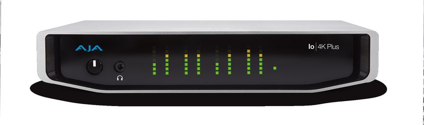
                             Warranty and Liability Information  .  .  .  .  .  .  .  .  .  .  .  .  .  .  .  .  .  .  .  . 61
                                    Limited Warranty on Hardware .  .  .  .  .  .  .  .  .  .  .  .  .  .  .  .  .  .  .  .  .  .  .  .  .  .  .  .  .  . 61
                                    Limitation of Liability .  .  .  .  .  .  .  .  .  .  .  .  .  .  .  .  .  .  .  .  .  .  .  .  .  .  .  .  .  .  .  .  .  .  .  .  .62
                                    Governing Law and Language; Your Rights.  .  .  .  .  .  .  .  .  .  .  .  .  .  .  .  .  .  .  .  .  .  .62

                             Index .  .  .  .  .  .  .  .  .  .  .  .  .  .  .  .  .  .  .  .  .  .  .  .  .  .  .  .  .  .  .  .  .  .  .  .  .  .  . 63

Io 4K Plus Capture, Display, Convert v15.1                                                   4                                                                                www.aja.com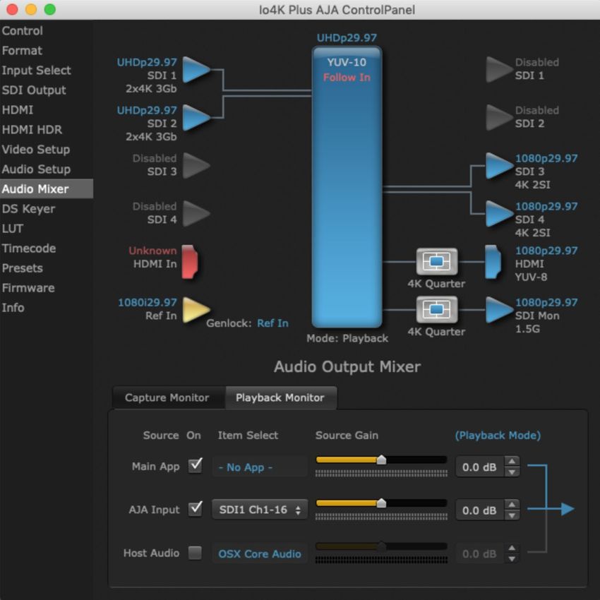
Chapter 1 – Introduction

Overview
                        AJA Io 4K Plus offers a full set of professional video and audio connectivity with
                        support for the latest 4K and UltraHD devices and High Frame Rate workflows.
                        The power of Thunderbolt 3 enables Io 4K Plus to handle a wide range of formats
                        from SD to HD, UltraHD and full 4K over both SDI and HDMI and support 4K frame
                        rates up to 60p, plus HDR 10 and HLG support over HDMI for HDR workflows.
                        Io 4K Plus is the ideal companion for lightning-fast video capture, playback and
                        editorial. Io 4K Plus connects with a single Thunderbolt cable and provides a
                        second Thunderbolt connector for flexibility, making it perfect for on set, or in
                        the edit suite.

         Features
                         • Two Thunderbolt 3 ports (a pass-through daisy-chaining)
                         • Four bidirectional SDI BNCs configurable for up to four inputs, or four outputs,
                           or two inputs and two outputs.
                         • Single Link I/O for 4K/UltraHD, HD and SD across 12G-SDI, 6G-SDI, 3G-SDI, and
                           1.5G-SDI
                         • Dual Link I/O for 1.5G-SDI and 3G-SDI (2 x BNC)
                         • Quad Link I/O for 1.5G-SDI, 3G-SDI (4 x BNC)
                         • Supports Quadrant or Two Sample Interleave transport
                         • Automatically downconverts Single Link 4K/UltraHD 12G input to HD on the
                           Io 4K Plus SDI 4 output
                         • HDMI 2.0 Input and Output
                         • HDR (HDR10 or HLG via HDMI, 12 Bit RGB, BT2020)
                         • Dedicated realtime 4K/UltraHD to HD down-conversion output (SDI Monitor
                           out BNC)
                         • Eight-channel Embedded HDMI audio
                         • Choice of Eight-Channel In, Eight-Channel Out, or Four-Channel In/Out analog
                           audio (DB25 cable, Line Level)
                         • Front panel LED VU meters and Headphone output w/level control
                         • Reference In/LTC In (selectable)
                         • LTC Output
                         • RS-422 control via 9-pin
                         • Rugged Chassis, Small Size
                         • 12V DC, 4-pin XLR Power (AC adapter included)

Io 4K Plus Capture, Display, Convert v15.1                       5                                            www.aja.com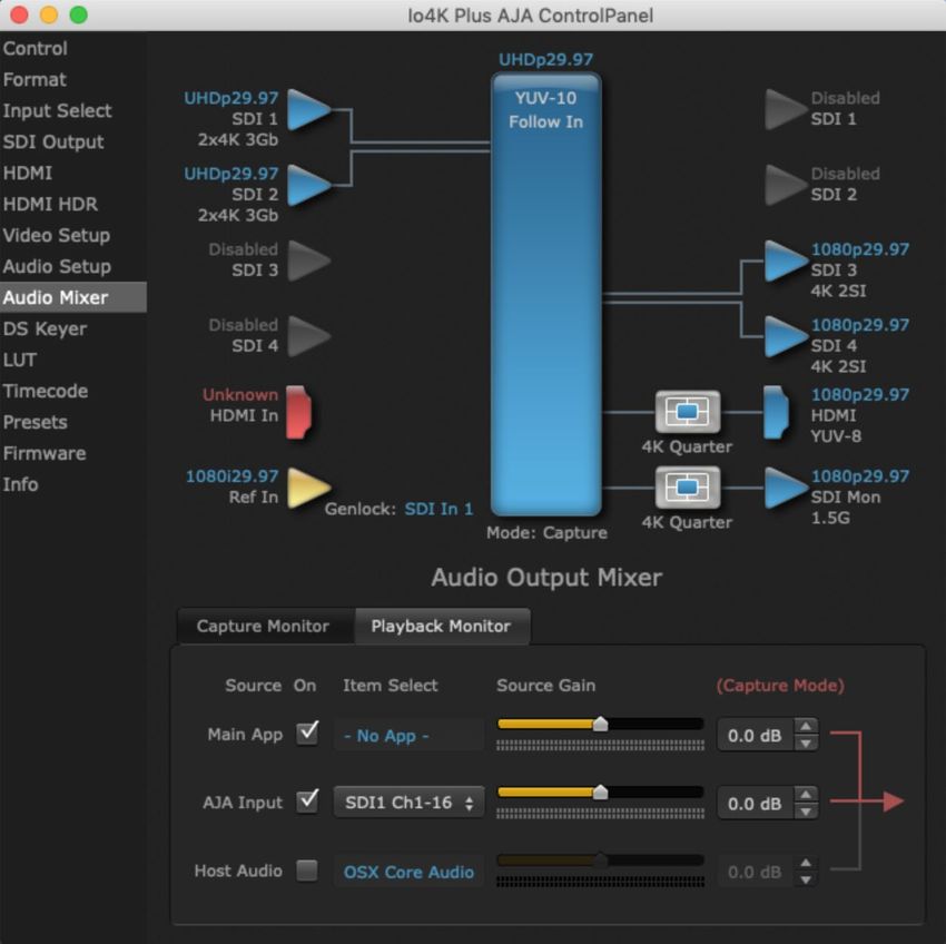
                 Video Formats
                        For a list of supported video formats, see "Appendix A Specifications" on page 50.

         High Quality Down Conversion
                        The Io 4K Plus built-in down-conversion 3G monitor spigot, uses large multi-point
                        digital interpolators, anti-alias filtering and interpolation. Because these functions
                        are in hardware, they are available full time, all the time—with no CPU load.

         Io 4K Plus Audio
                        Io 4K Plus provides up to 16 channels of SDI embedded audio, and up to eight
                        channels of embedded HDMI audio. Eight channels of analog audio I/O is
                        supported via a DB25 industry standard Tascam style audio breakout cable. The
                        eight analog audio channels can be configured as either Ch 1-8 input, Ch 1-8
                        output, Ch1-4 input with Ch 5-8 output or, Ch 1-4 output with Ch 5-8 input.

         AJA Software & Utilities
                        Io 4K Plus operates with AJA's Desktop software package, developed for powerful
                        integrated video/audio capture, editing, and production with a variety of 3rd-
                        party software. AJA software is distributed as a unified package which includes all
                        the software, firmware, plugins, and utility programs for the Io 4K Plus, as well as
                        AJA’s Io, KONA, and T-TAP products.
                        Two retail packages are available, one for Mac and one for Windows.

                 Mac and Windows Packages
                        These packages include:

                        Drivers
                        AJA device drivers for tightly integrated hardware/software operation.

                        AJA Control Panel
                        The Control Panel provides:
                         • Source selection and control of your AJA hardware.
                         • A block diagram to show visually what routing and processing is being
                           performed.

                        AJA Control Room
                        Control Room is a cross-platform software application for ingest, playback and
                        output with AJA products.

                        AJA System Test
                        System Test provides accurate and detailed evaluations of drive and PCIe
                        performance statistics, allowing you to measure the capabilities of your system
                        for recording and playing back various resolutions and codecs.

                        3rd-Party Plugins
                        Plugins for popular 3rd-party Professional Video Applications from Adobe, Avid,
                        Apple, Telestream, and others.

Io 4K Plus Capture, Display, Convert v15.1                        6                                              www.aja.com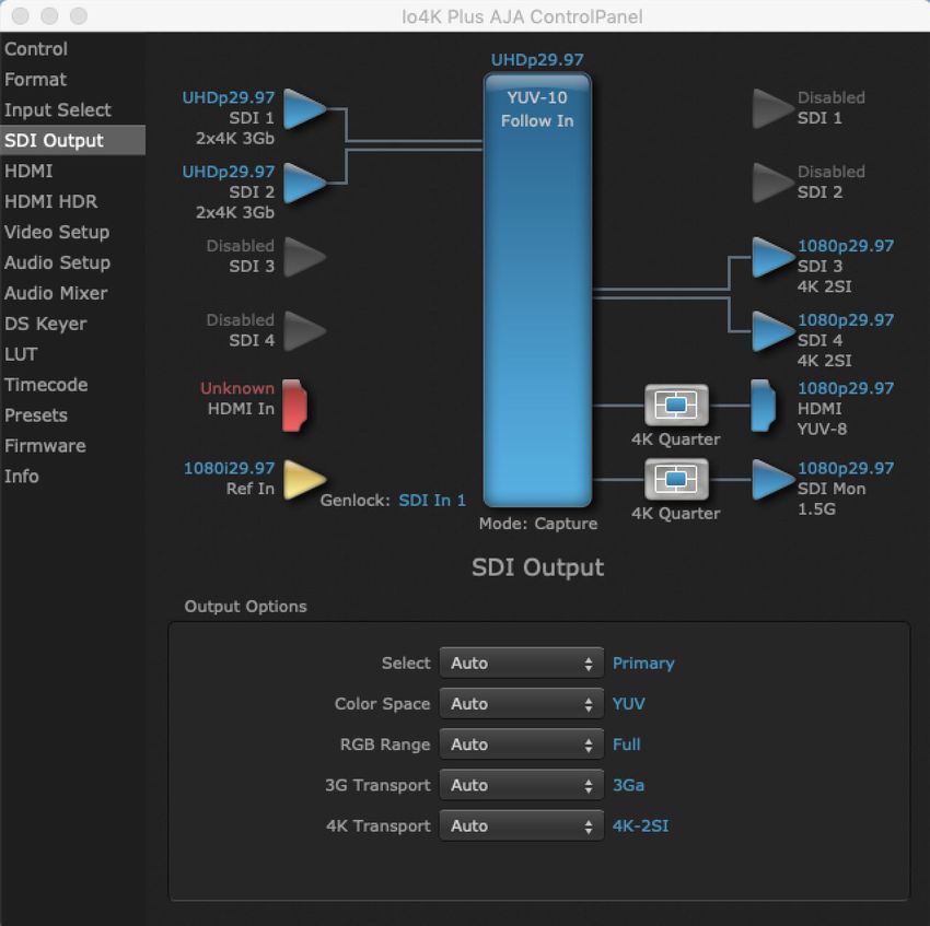
System Requirements
                        Your system should meet minimum hardware and software requirements to
                        achieve a satisfactory level of performance. Updates to system requirements are
                        subject to change.
                    NOTE: See Software Vendor system requirements for GPU and additional hardware
                          recommendations.
                        Recommended system specifications:
                         • Mac OS 10.12 Sierra or later
                         • Win 10 or later with all updates
                         • 2.5 GHz quad core i7 minimum, for HD
                         • 3.5 GHz eight core minimum, faster processors and more cores recommended,
                           for UltraHD/4K workflows, especially with high frame rate*
                         • 16GB RAM minimum, 32GB or more recommended, especially for UltraHD/4K
                           or High Frame Rate applications
                         • A reasonably fast and powerful graphics card, with plenty of on-board
                           memory. Examples (may be specific to application version and/or host CPU)
                           include:
                           • Nvidia K5200
                           • Nvidia K4200
                           • Nvidia M6000
                           • Nvidia M5000
                           • Nvidia M4000
                           • AMD W7100
                           • AMD W8100
                         • Media storage with adequate bandwidth to sustain the capture and playback
                           of the material you expect to be working with.
                    NOTE: For large scale installations with shared storage, or for very high performance
                          requirements, consultation with an experienced a system integrator is
                          recommended. A consultant will be able to assist with many important variables.

What’s In The Box?
                        As you unpack the shipping box, carefully examine the contents. Ensure you
                        received everything and that nothing was damaged during shipment.
                        If you find any damage, immediately notify the shipping service and supply them
                        with a complete description of the damage, and contact your dealer or distributor
                        for details on how to have your Io 4K Plus repaired or replaced.
                        Save packing materials and the shipping box for future use should you need to
                        transport your system or return it for service.
                        Inside the box you’ll find the following components:
                         • Io 4K Plus
                         • 12V power adapter and power cord

In This Manual
                        Chapter 1 - Introduces the product briefly, listing features and system
                        requirements.

Io 4K Plus Capture, Display, Convert v15.1                       7                                          www.aja.com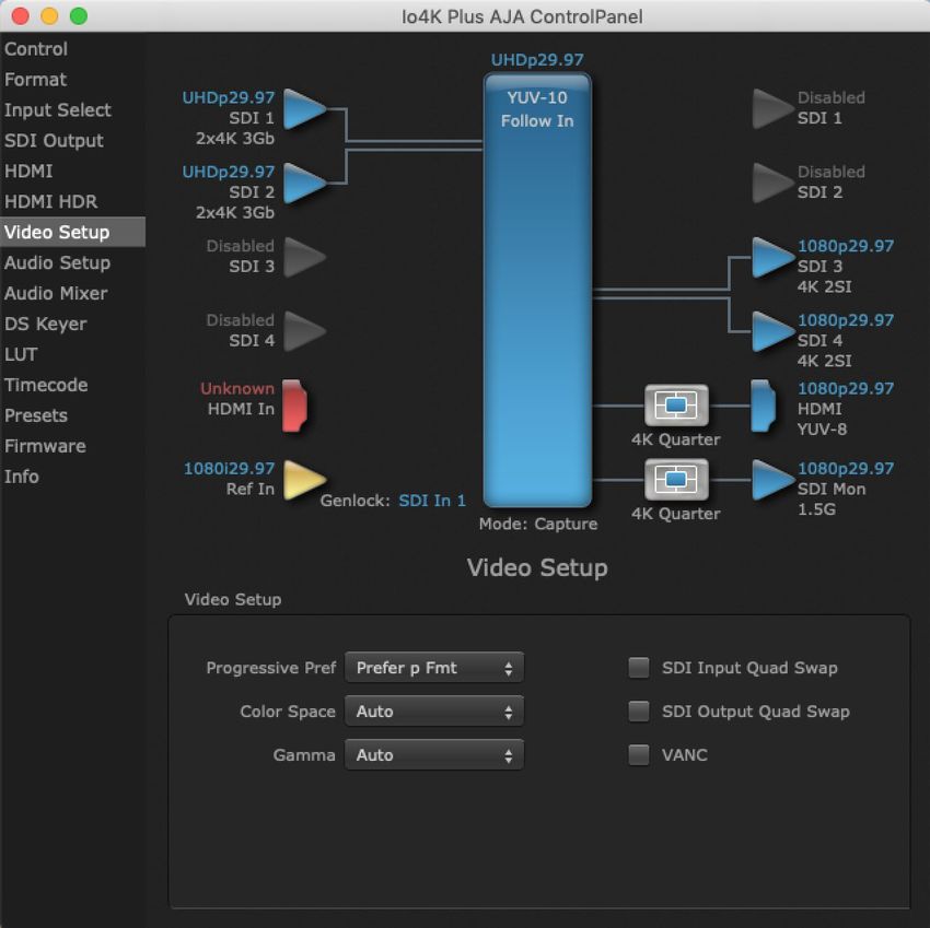
                        Chapter 2 - Provides complete instructions for installing and configuring the
                        product.
                        Chapter 3 - Discusses operational aspects and how to work with 3rd-party
                        software.
                        Appendix A - Presents a list of technical specifications for the product.
                        Appendix B - Provides important Safety and Compliance information.

Io 4K Plus Capture, Display, Convert v15.1                        8                                     www.aja.com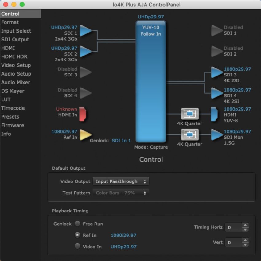
Chapter 2 – Installation

Installation Overview
                        1. If not previously installed on your Thunderbolt equipped computer, ensure
                           that appropriate third party application software is installed as detailed in
                           its user documentation.
                        2. Download and install the latest Io 4K Plus software from:
                            https://www.aja.com/en/support/downloads
                        3. Connect your Io 4K Plus to your computer using an appropriate Thunderbolt
                           cable.
                        4. Connect the video and audio inputs and outputs.
                        5. Power up the unit (AC supply or battery). The Io 4K Plus will startup
                           automatically.
                        6. AJA recommends that you now run AJA Control Panel, as this allows you to
                           verify that the installation has completed successfully.
                    NOTE: AJA Control Panel will prompt you to update firmware (if the new software
                          package contained a firmware update for your AJA device).

         System Test Application
                        AJA System Test is a utility for measuring system performance. The application
                        includes:
                         • System Disk Test
                         • AJA Device Test
                         • Disk + Device Test
                         • System Report
                        The application tests Read and Write, Capture and Playback speeds tests in both
                        Megabytes per second and Frames per second. The disk speed tests differ from
                        standard disk I/O performance applications in that they specifically test the
                        system under conditions typically encountered with video capture, playback, and
                        editing.
                        Theoretically the best test is to fill your storage disk to 80% and then test capture
                        at the highest data rate you will use.

Io 4K Plus Capture, Display, Convert v15.1                        9                                             www.aja.com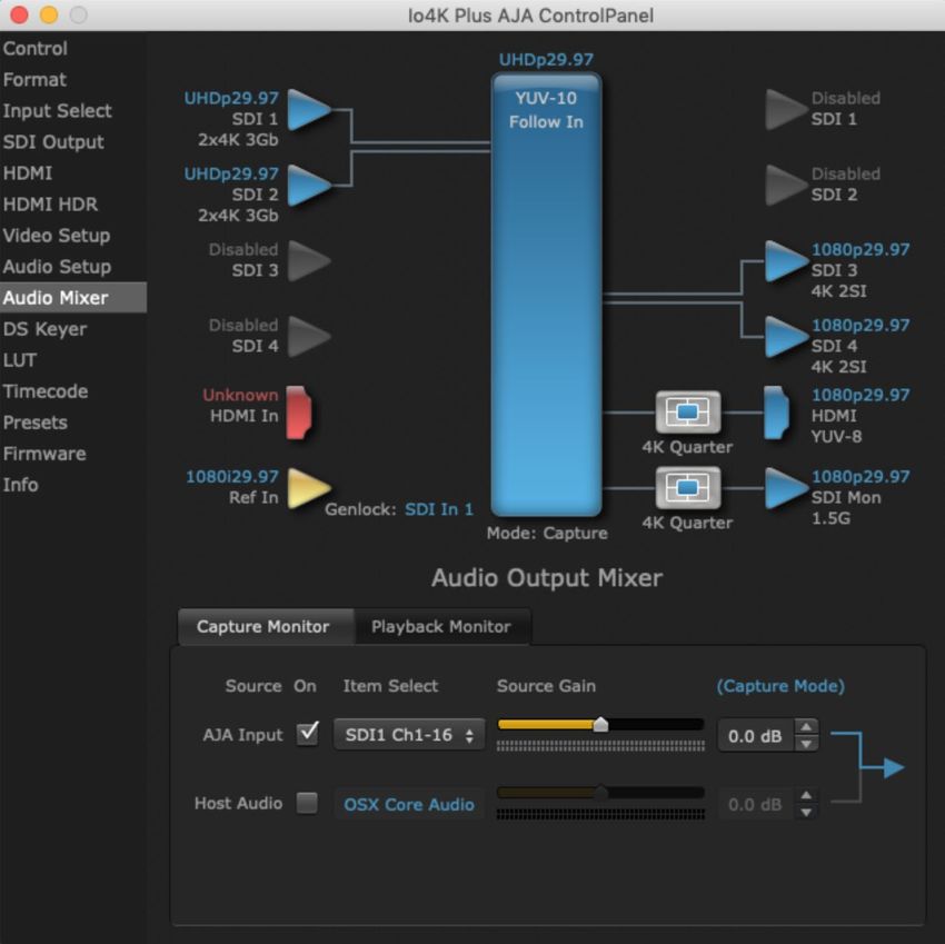
         Cable Connections
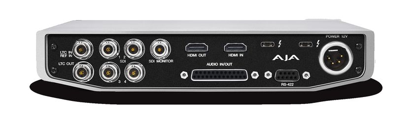
                        Figure 1. Io 4K Plus Connectors
                                      Bidirectional
                              12G/6G/3G/HD/SD-SDI BNCs (4)
                       Reference or              HD/SD-SDI     HDMI          HDMI    Thunderbolt 3
                        LTC Input              Monitor Out BNC Output        Input     Ports (2)

                        LTC Output                Balanced Audio In/Out      DB-9F RS-422              4-Pin XLR
                                                      DB-25F (8-Ch)         Machine Control          DC Power Input

         Connector Descriptions

                 Thunderbolt 3
                        The Io 4K Plus provides the third-generation Thunderbolt 3 (USB-C) ports to
                        support increased bandwidth between host computer and I/O device. Two ports
                        are provided for daisy-chained network configurations.

                 Bi-directional SDI I/O
                        Four bidirectional BNC connectors can be configured in a variety of ways via the
                        AJA Control Panel, including:
                         • Two HD/SD inputs (SDI 1 and SDI 2) and two outputs (SDI 3 and SDI 4)
                         • Two 4K/UltraHD single-link 6/12G inputs (SDI 1 and SDI 2) and two 4K/UltraHD
                           single-link 6/12G outputs (SDI 3 and SDI 4)
                         • One 4K/UltraHD two-link 3G input (SDI 1 and SDI 2) and one and one two-link
                           3G output (SDI 3 and SDI4)
                         • One 4K/UltraHD four-link 1.5/3G input (SDI 1, SDI 2, SDI 3, and SDI4) input,
                           Quadrant or 2SI.
                         • One 4K/UltraHD four-link 1.5/3G output (SDI 1, SDI 2, SDI 3, and SDI4) output,
                           Quadrant or 2SI.

                 Dedicated SDI HD/SD Output
                        One BNC connector is provided for full-time, real-time output of HD/SD video. 4K
                        video is down-converted to 2K HD and UltraHD is down-converted to HD.

                 HDMI Input and Output
                        Two HDMI connectors provide input and output of HDMI video and multi-
                        channel embedded audio.
                         • HDMI 2.0 input and output, supporting UltraHD and 4K resolutions at up to
                           60p (4:2:2), 10-bit and 8-bit
                         • Supports two or eight channel HDMI audio input and output

Io 4K Plus Capture, Display, Convert v15.1                     10                                                www.aja.com
                        HDMI output also supports:
                         • HDR 10 Support - HDR Infoframe metadata, compatible with HDMI 2.0a/CTA-
                           861.3
                         • HLG Support - compatible with HDMI 2.0b/CTA-861-G
                    NOTE: HDCP is not supported on either input or output. 4K HDMI output does not have
                          HDCP, and input sources having HDCP are not supported.
                        The HDMI input is designed to support long cable runs—up to 100 ft. when using
                        22 or 24AWG HDMI cable, or up to 50 ft. using 28 or 30AWG HDMI cable. The
                        HDMI output supports standard HDMI cables only.

                 RS-422 Machine Control
                        A female DB-9 connector provides connection for VTRs, camcorders, disk media
                        servers, and other devices using RS-422 SMPTE (Sony) protocol.

                 Reference Video and LTC Input
                        Two BNC connectors provide reference Input and LTC output. The Reference
                        Video input can also be used for LTC input. The selection of Reference (sync) or
                        LTC is set using the AJA Control Panel ("Input Select Screen" on page 25).
                        Supplying a reference signal to the Reference input allows you to synchronize
                        Io 4K Plus outputs to your house analog reference video signal (or black burst).
                        When connecting a reference video source, the locking signal should be the
                        same as the input format. It is possible in some circumstances to use an alternate
                        format video signal as long as the basic frame rate is compatible.

                 Balanced Analog Audio Input and Output
                        A 25-pin connector provides 8-channel balanced analog audio, 24-bit 48kHz
                        sample rate D/A and A/D, for use with an industry standard 8x XLR on DB‑25
                        breakout cable (cable not included). The eight analog audio channels can be
                        configured four different ways:
                         • Ch 1-8 Output
                         • Ch 1-4 Input and Ch 5-8 Output (default)
                         • Ch 1-4 Output and Ch 5-8 Input
                         • Ch 1-8 Input

                 12V Power Connector
                        A standard 4-pin XLR type connector is provided for either battery or line source
                        power using the supplied AC power adapter.

Installing Software
                    NOTE: If your computer has previously had another video capture or multimedia device
                          installed, ensure you uninstall any related software before installing Io 4K Plus.
                          This will prevent any hardware or software conflicts.
                        Before installing the software package, ensure that your capture/editing
                        application is installed as detailed in its user documentation. Before using
                        Io 4K Plus with Avid Media Composer or other NLE application, it is best practice
                        to have installed and run the software at least once on your workstation. Next,
                        install the AJA software package.

Io 4K Plus Capture, Display, Convert v15.1                       11                                            www.aja.com
                        If at a later date you add any Io 4K Plus supported applications that require
                        drivers, you must run the AJA install program again to install them.

Io 4K Plus Capture, Display, Convert v15.1                       12                                     www.aja.com
Chapter 3 – Io 4K Plus Operation
                                                                      Audio Level     Power
                                                                       Meters (8)      LED

                        Monitor                 Monitor Output
                      Gain Control            Connector 1/8 in. TRS

Front Panel Operation
                        The Io 4K Plus front panel has the following controls and indicators:

         Monitor Output and Gain Control
                        A 1/8 inch TRS connector is available for monitoring two channels of audio,
                        selectable in channel pairs using the Control Panel application. Typically used
                        with a pair of headphones.
                        The Monitor Gain knob on the left adjusts the monitor output level. Pushing in
                        the knob extends it (for adjustment) or recesses it (to prevent accidental changes).

         Audio Level Meters
                        The Audio Level Meters in the center of the front panel indicate:
                         • During Capture - The first 8 channels of the audio source selected (SDI, HDMI,
                           Analog).
                         • During Playback - The sum of whatever sources are being played out via
                           the AJA hardware; i.e. NLE timeline and mix of host system audio output (if
                           applicable).
                        The meter's LEDs are colored to indicate the amount below 0dBfs when averaged
                        over a one millisecond time interval:

                         dBfs                LED Color and Location
                         -2 db               Red LED 1 (top)
                         -12 db              Yellow LED 2
                         -20 db              Yellow LED 1
                         -30 db              Green LED 4
                         -40 db              Green LED 3
                         -50 db              Green LED 2
                         -60 db              Green LED 1 (bottom)
                    NOTE: These audio level meters are for guidance only. Third-party audio metering
                          should be employed when doing critical audio editing and mixing.

Io 4K Plus Capture, Display, Convert v15.1                            13                                       www.aja.com
         Power LED
                         The power LED lights up yellow when power is provided via the power supply.
                         Once a Thunderbolt 3 connection is made, and the host is in an active state, the
                         light turns green.

AJA Control Panel Overview
                         The AJA Control Panel is a software application that provides a simple visual
                         showing how the Io 4K Plus hardware is currently configured and allows you to
                         make changes. You can change signal input and output parameters and define
                         the video processing that will be performed.
                         The AJA software installer automatically installs the Control Panel application on
                         your computer. You’ll find the AJA Control Panel application in your Applications
                         folder.

         AJA Control Panel User Interface
                         The AJA Control Panel user interface includes a visual block diagram of the unit’s
                         current configuration. The current status, input and output settings, and many
                         other details are depicted in the color-coded block diagram. Below this block
                         diagram are various controls for changing operating parameters, which will vary
                         depending on which function screen has been selected.
                         The left side of the AJA Control Panel provides a navigation list of available
                         function screens. Clicking on a link (or alternatively, a related element in the block
                         diagram) displays a function screen corresponding to that topic.
                         Figure 2. Io 4K Plus, Block Diagram set for UltraHD Format
                                                                                   Framebuffer Format (Primary)
               Currently
               Selected                                                                                            Controlling
               Function                                                                                            Application
                Screen

                Inputs
                                                                                                                       Outputs

                                                                                                                  Operating
                                                                                                                   Mode

              Parameter
               Controls

Io 4K Plus Capture, Display, Convert v15.1                         14                                               www.aja.com
                 Block Diagram Area
                        The top block diagram area of the Control Panel screen is a visual representation
                        of the processing, if any, that’s currently occurring, including inputs/outputs,
                        reference source, and system status. Lines between inputs, the framebuffer, and
                        outputs, show a video path. Where there are no lines, there is no connection; this
                        can be because an input or output isn’t selected in the Input Select menu. The
                        lines will also show whether the outputs are video or video + key.
                        You can click any of the function screen selection links in the left column to view
                        its current settings or click on an icon to call up its related settings screen. You can
                        also right-click or Control-click to see context-sensitive information and choices
                        (Figure 3).
                        Figure 3. Context Sensitive Menu

                 Color Meanings
                        All items in the AJA Control Panel block diagram are color-coded to show what is
                        happening in real time. This applies to both icons and text. These colors indicate:
                        Blue - Video is same format as the Primary Format (framebuffer)
                        Yellow - Reference video (black burst or other reference source)
                        Red - The selected operation cannot be performed

                 Input/Output Icons
                        The input and output icons are triangles that together with their color show all
                        the input and outputs and their status (selected, not selected, input present or
                        not, format, etc.). A complete video path is shown when inputs and outputs are
                        connected with lines going to/from the framebuffer.
                        Figure 4. Input/Output Icons

                 Framebuffer
                        The framebuffer is the “engine” where your third-party applications interface with
                        the AJA device. The framebuffer has a format (called the “Primary Format”) and
                        color space that it follows, as defined in the linked menu screens or via external
                        application software.

                 Primary Format
                        The Primary Format is the media format written to disk and used in your project.
                        This is the format that the framebuffer will use and is shown in the Control Panel
                        using the color blue. It is the format that the third-party application software will
                        either receive from the AJA hardware, or is sending to the hardware. All icons in
                        blue are the same as the Primary Format used by the framebuffer. Also any text
                        descriptions in the block diagram that appear in blue indicate that something is
                        in the primary format.

Io 4K Plus Capture, Display, Convert v15.1                        15                                               www.aja.com
         Controlling Application
                        It is important to understand that the computer can contain many applications
                        that can use the AJA device (as you switch from window to window) and it may
                        not always be obvious which currently controls it.
                        Figure 5. Control Panel In Use Message (in red)

                        In the top right corner, the Control Panel displays the name of the application
                        controlling the unit. In some cases, applications may not always properly “let go”
                        of the I/O interface as another takes over—you’ll be able to tell by looking at the
                        Control Panel.

         Presets
                        Setups can be named and saved as a snapshot (Preset) for recall at any time. You
                        can save various AJA device Control Panel configurations associated with your
                        frequent tasks. You don’t have to spend time resetting interface configurations,
                        just load the previously saved Preset for each task. See "Saving, Loading and
                        Deleting Presets" on page 47 for more information.
                        If you work on multiple systems and want to carry your saved setups to another
                        location, you can copy your saved Preset files on to movable storage and load
                        them into any computer running the AJA Control Panel application.

                        Mac OS Preset Files Storage Location
                         • From the Finder, hold down the Option key (to display the Library directory)
                           and click on Go/Library/Application Support/AJA//Presets/

                        Windows Preset Files Storage Location
                         • c:\Users\\AppData\Local\AJA\Control Panel\
                           Presets\

         Default Preferences
                        When an AJA device starts up, a preference can determine what settings it will
                        have it when it begins to operate. The AJA Control Panel offers two default
                        preference settings:
                         • Local Preference - A preference stored from the last AJA device's Control Panel
                           settings to be used on next startup of AJA Control Panel. This occurs on next
                           restoration of the default state (triggered by start up of host CPU, startup of
                           the AJA device, or when a third-party application releases the AJA device).
                         • Global Preference - A preference saved for use as a global default start state
                           for an AJA device that can be shared by multiple users, applied on first startup,
                           or by pressing the Control Panel Reset Device... button.

Io 4K Plus Capture, Display, Convert v15.1                       16                                            www.aja.com
                 Local Preference
                        The Local Preference file (com.aja.devicesettings) exists to immediately and
                        automatically store all parameter changes made by a user on a particular AJA
                        device. When any control is changed in the Control Panel, that change is recorded
                        in the Local Preference file stored in a unique location on that computer that is
                        dedicated to that particular device, serial number, and logged-in user. Then, when
                        AJA Control Panel is restarted for any reason, the AJA device being controlled
                        restores the settings being used when Control Panel was last closed.
                        The Local Preference file can be accessed at the following locations.
                        On Mac:
                           • From the Finder, hold down the Option key (to display the Library directory)
                             and click on Go/Library/Preferences/com.aja.devicesettings.
                        On Windows:
                           • C:\Users\\AppData\Local\aja\com.aja.devicesettings
                    NOTE: Clicking on the AJA Control Panel "Erase All Prefs" button deletes the existing
                          Local Preference file from this location. This file will be recreated as soon as any
                          Control Panel setting is changed.
                    NOTE: Clicking on the AJA Control Panel "Reset Device..." button will delete the existing
                          Local Preference file. If a Global Preference file is found, these settings are
                          reloaded. If a Global Preference file is not found, “factory defaults” are loaded and
                          the device is set to that state

                 Global Preference
                        An administrator can establish a house standard for an AJA device by copying
                        a preference file to a shared computer location. Once placed at that location, it
                        becomes a Global Preference file where it will establish a standard default startup
                        state for all users of that AJA device using that computer system. These settings
                        preempt the initial AJA factory default settings, and are applied when an AJA
                        device is first powered up, or when the Control Panel Reset Device button is
                        pressed.
                        To establish a Global Preference, the administrator first configures the AJA device
                        (which automatically creates a "com.aja.devicesettings" Local Preference file in
                        the location identified above) and then copy or move or that file to the correct
                        computer locations (manually or by pushing it out across the network) on all the
                        computers that use the AJA device.
                    NOTE: If the user makes changes to an AJA Device's Control Panel settings, those
                          changes are saved to the Local Preference file, which will take priority over the
                          Global Preference file.
                        The shared computer locations for a Global Preference file are:
                        On Mac:
                         • From the Finder, click on Go/Computer//Users/Shared/AJA/
                           and copy or move the "com.aja.devicesettings file" described above to this
                           location.
                    NOTE: The "AJA" folder needs to be created manually at this location before moving the
                          preference file into it.
                        On Windows there are three possible shared locations depending on your system:
                         • C:\Users\Public\Aja\
                         • C:\Users\All Users\Aja\
                         • C:\ProgramData\Aja
                            Copy or move the "com.aja.devicesettings file" described above to one of
                            these locations.

Io 4K Plus Capture, Display, Convert v15.1                         17                                             www.aja.com
                    NOTE: The AJA Control Panel Info screen displays the path to the Global Preference file
                          on that computer.
                    NOTE: Clicking on the AJA Control Panel Erase All Prefs button does NOT delete an
                          existing Global Preference file from this location.

         Function Screens
                        Listed below are the function screens for Io 4K Plus and what they are used for.

                        Table 1. Io 4K Plus Function Screens
                         Screen              Functions
                         Control             Configure basic Io 4K Plus operation options and output timing.
                         Format              Select the framebuffer primary video format settings.
                         Input Select        View and edit input selections and audio mapping.
                         SDI Out             Select output format.
                         HDMI                Configure the HDMI I/O
                         HDMI HDR            Configure High Dynamic Range settings for HDMI output
                         Video Setup         Configure Video such as composite black level, progressive format and
                                             ancillary data (Closed Caption) option.
                         Audio Setup         Configures Audio options such as analog audio input and output
                                             channels, audio monitor level, and audio delay.
                         Audio Mixer         Select and mix audio sources for monitoring.
                         DS Keyer            Setup and control the insertion of keyed video from the frame buffer or
                                             graphics files with alpha channel.
                         LUT                 Load a lookup table (LUT) file to adjust the calibration of color for any
                                             source.
                         Timecode            Monitors SMPTE 12M-2 timecode and configure timecode window burn
                                             output.
                         Presets             Add or delete saved preset configurations (handy for quick and easy recall
                                             of different Io 4K Plus settings for varied workflows).
                         Firmware            Install firmware from your currently installed AJA software package.
                         Info                Display status information and the firmware version number. This
                                             information is generally intended for troubleshooting/support.

Using Io 4K Plus for UltraHD/4K
         4K/UltraHD Transport Modes
                        The 4K and UltraHD SDI formats can use different transport modes, associated
                        with the number of links used to transport the signal, the data rates involved, and
                        the way the image data is organized.
                        Io 4K Plus supports both Quadrant and Two Sample Interleave (2SI) transport
                        standards. Many different combinations of modes and data organization exist.
                        In 4K mode, single link transport is available as either 12G or 6G (which are both
                        2SI). Whether the video is auto-sensed as 12G vs. 6G is dependent on the data rate
                        of the incoming or outgoing signal. For example, 4K p30 at 8bit 4:2:0 requires 6G
                        only.

Io 4K Plus Capture, Display, Convert v15.1                           18                                                  www.aja.com
                        Besides single link transport, Io 4K Plus also supports the following multiple link
                        transport modes for UltraHD and 4K:
                         • Quadrant 4-wire (transported on four links)
                         • Quadrant 2-wire (transported on two links)
                         • 2SI (two or four links automatically selected)
                        The amount of data in the signal affects the number of links and data rates
                        necessary to carry that signal.

                 Quadrant Mode
                        In Quadrant Mode you can use four HD or 2K signals (1.5G) to input / output
                        UltraHD or 4K at 30fps or below, or four 3G signals to enable HFR and / or deep
                        color. Whether using four 1.5G or four 3G wires, each represents individual
                        quadrants of the higher definition UltraHD 3840x2160 or 4K 4096x2160 4K
                        formats. Physical connections of the quadrants will be mapped to the SDI
                        connectors as shown. Monitoring one of these HD signals on a standard SDI
                        monitor will display one quadrant of the picture.
                        Figure 6. Mapping of Quad SDI Outputs

                 2SI Mode
                        Two Sample Interleave is an alternative method to organize the data of SDI
                        UltraHD and 4K formats. Instead of dividing the picture raster into quadrants,
                        this method samples pixels to create four lower resolution versions of the entire
                        picture. These are combined later to create the full resolution image.
                        Figure 7. Mapping of 2SI Outputs

                        For 2SI UltraHD or 4K SDI video at 30 fps or less, monitoring one of these four
                        signals on a standard SDI monitor displays the entire picture, but at a lower
                        resolution. Above 30 fps, 3G bandwidth is required, so a 3G capable monitor is
                        required.”
                    NOTE: In some versions of AJA Control Panel, the 2SI method is referred to as ‘425’ which
                          is a reference to the SMPTE 425 standard which defines this method.

                 2-Wire and 4‑Wire Modes
                        Using higher data rates, it is possible to carry UltraHD and 4K signals on two SDI
                        links, instead of four. In this situation, half (two quarters) of the image data is
                        carried on one link, with the other half carried on the other link. These types of
                        signals also cannot be viewed on a standard SDI monitor using one connector.

Io 4K Plus Capture, Display, Convert v15.1                       19                                             www.aja.com
                        You can choose 2-wire or 4-wire input and output (depending on the type of
                        signal). If the number of links selected is not sufficient, the number of links is
                        automatically increased to accommodate the signal. UltraHD or 4K SDI signals 30
                        fps and below can be input and output simultaneously, using two connectors in
                        each direction. However, all four connectors are required above 30 fps. You will be
                        able to either input or output a high frame rate SDI signal, not both at the same
                        time. In this situation, you can use the down-converted SDI monitor output to
                        monitor the input signal, or use the HDMI output. Note that to monitor incoming
                        UltraHD/4K SDI as HDMI UltraHD/4K, the SDI input transport must be 2SI. Quad
                        SDI will be down-converted to HD on the HDMI output.
                        Specifying the number of wires for output forces Quadrant mode. You cannot
                        specify the number of links when 2SI output is selected (the lowest number of
                        links will be set automatically).

                 Single-Wire Modes
                        KONA 5 supports 12G SDI and 6G transport over a single link. All formats
                        described above can be carried on this link, but the associated source and
                        destination equipment must support single-link 12G (high frame rate) or 6G
                        (lower frame rate) video.
                        In Single-Wire 12G output mode, KONA 5 automatically outputs a down-
                        converted 2K or HD signal on SDI output 4, along with the 4K/UltraHD signal sent
                        to SDI output 3.

Io 4K Plus Audio Monitoring
                        Io 4K Plus hardware can be used as your single audio monitoring solution
                        whether you are auditioning music in a web browser, playing a movie file on
                        the desktop, creating music, or playing a YouTube clip. As long as the output of
                        your work or application is normally output via the host system audio, your AJA
                        hardware can route this audio for monitoring. This cuts down on unnecessary
                        cabling, and means you can take advantage of a consistent audio monitoring
                        environment whatever you are currently doing with your host system.
                    NOTE: On first use, you will need to tell your operating system to use AJA hardware as
                          the default Input and Output hardware.
                        Io 4K Plus lets you listen to Host System audio concurrently with your NLE audio.
                        This is useful if you need to audition music tracks against playback of your NLE
                        timeline, or if you need to Skype with a remote producer during an edit session,
                        or for a myriad of other reasons.
                        You can also listen to Io 4K Plus Input concurrently with your NLE (with the
                        exception of Avid Media Composer). This is useful if you need to listen out for the
                        readiness of talent, or the presence of some other feed, whilst you continue to
                        work.
                        Io 4K Plus audio monitoring is routed and mixed using the Control Panel
                        application's Audio Mixer screen. You can select sources to be monitored, and
                        can adjust their levels. If you are using the 1/4 inch monitor output connector, an
                        additional overall mix gain control is conveniently available on the Io 4K Plus's
                        front panel.
                        The mixed audio monitor signal is also routed to:
                         • SDI Audio out
                         • HDMI Audio Out
                         • Analog Audio Out (via DB25 cable)

Io 4K Plus Capture, Display, Convert v15.1                       20                                           www.aja.com
                    IMPORTANT: Even though you can hear changes in the signals and levels adjusted with
                          the Audio Mixer screen, these changes are NOT recorded to disk during NLE
                          Capture or Audio Punch In / Voice Over to Timeline. The Audio Mixer screen is
                          dedicated for monitoring only, not program mixing.

                        Figure 8. Io 4K Plus Audio Monitoring Routing Diagram
                                             Audio Capture
                                           Punch In/Voice Over
                                              Record to File

                          Non Linear
                          Video Editor             NLE
                                                Application                 NOTE: NLE audio
                                                                            output is disabled
                                                                            in Capture mode.

                                Control Panel                                            Control Panel
                                                                                                                            AJA Hardware
                                 Input Select                                             Audio Mixer
                                   Screen
                                                                                                                           Audio Monitoring
                                                                             NLE            Screen
                                                                             Audio                                            SDI Embedded
                                                                                                                               Audio Output
                                                                 AJA Hardware Audio
                                                                                                                             HDMI Embedded
                          AJA Hardware                                                                    Mixer               Audio Output
                                                                                                         Controls
                           Audio Input                                                                                        Analog Audio
                           SDI Embedded                                                                                         Output
                            Audio Input                                                                                        Front Panel
                                                                             Host                                             Monitor Output
                          HDMI Embedded                                    Computer
                            Audio Input                                     Audio                                   Gain
                                                                                                                    Knob
                           Analog Audio
                              Input

                          Host Computer Audio Input
                            Audio File
                            Playback
                                                Mac or PC
                             YouTube            Computer
                              Other               Audio
                             Sources

                        To control which AJA hardware audio is used during recording, you use the
                        Control Panel application's Input Select Screen, Audio Input Select drop down to
                        select from
                         • SDI embedded
                         • HDMI embedded
                         • Analog (via DB25 cable)
                        Any level adjustments to Capture or Audio Punch In / Voice Over to Timeline
                        recording operations will either need to be made upstream of the AJA input, or
                        else via adjustments within the main NLE application (e.g. via a pass through mix
                        tool).

Io 4K Plus Capture, Display, Convert v15.1                                    21                                                             www.aja.com
AJA Control Panel Function Screens
         Control Screen

                        The Control Screen is where you set the Default Output, what the device outputs
                        when no application has control of the board. This screen also has controls for
                        setting the genlock source, and for setting the Horiz and Vert timing offsets. The
                        top of the Control Screen shows the current state of the device and also shows
                        the name of the Application which has control of the board, if there is one.

                 Default Output
                        Many video applications can grab control of the Io 4K Plus, so its outputs can
                        change dynamically. The Default Output settings are used to select what will be
                        output when no third-party video application is controlling Io 4K Plus.

                        Video Output
                         • Input Passthrough - This selection directs Io 4K Plus to route video from its
                           selected input through the card for processing and output.
                         • Test Pattern - This selection directs Io 4K Plus to output a preset pattern
                           when no other application is in control. The pattern is selected from the Test
                           Pattern dropdown list below, or a graphic file can be chosen.
                         • Hold Last App - This selection directs Io 4K Plus to hold and output the last
                           frame of video from the last application to control Io 4K Plus. This can be
                           helpful when operating in an environment where you’re switching back and
                           forth between multiple application windows.

Io 4K Plus Capture, Display, Convert v15.1                      22                                           www.aja.com
                        Test Pattern
                        With Test Pattern selected above, you can choose the pattern type. Select from:
                         • Black, Color bars (75% or 100%), Ramp, Multiburst, Line Sweep, Multi Pattern,
                           or Flat Field, Check Field, White, Border, Linear Ramp, Slant Ramp, Zone Plate,
                           Color Quadrant, or Color Quad Border.

                        Graphic File Display
                        In addition to the test patterns above, a “Load File...” selection at the bottom
                        of the Test Pattern dropdown menu allows you to load a standard RGB/RGBA
                        graphics file (.tif,.psd, etc.) into the frame buffer for display (including alpha
                        channel). Some graphics formats and bit depths may not be supported. Files that
                        have been loaded are listed for quick reuse. Loaded graphic files are retained for
                        redisplay if another test pattern is selected, and even if Io 4K Plus is power cycled.
                    NOTE: A loaded graphics file will not be scaled to fit. If it’s smaller than the current frame
                          buffer format,Io 4K Plus will center it in the frame. If larger than the current frame
                          buffer format it will be cropped.
                         • Clear Files - This selection on the pulldown clears all the Graphic Display files.

                 Playback Timing
                        Use these controls to set the Genlock source and Timing adjustment.

                        Genlock
                        Selects how Io 4K Plus will synchronize program video:
                         • Freerun: Generates sync without an external reference source
                         • Ref In: Use the Ref Video source for sync (usually an analog black burst video
                           signal)
                         • Video In: Use whichever video input source has been selected in the Inputs
                           screen for sync
                        For video stability and proper system operation, you can genlock all equipment
                        to house sync. However genlock is not required for Io 4K Plus due to its excellent
                        freerun accuracy. On the Io 4K Plus house sync is connected to “LTC/Ref In”.
                        Alternatively, Io 4K Plus can receive externally supplied Linear Time Code on that
                        same input connector. The LTC/Ref setting on the Input Select screen (see "LTC/
                        Ref" on page 26) selects how that input signal will be used.

                        Timing (Horiz and Vert)
                        These two pull-downs allow output timing adjustment with reference to the Ref
                        Video source selected.
                         • Horizontal: The Horizontal reference can be adjusted by selecting a number of
                           pixels (clocks) to offset
                         • Vertical: The vertical reference can be adjusted by specifying a number of lines
                           to offset.

Io 4K Plus Capture, Display, Convert v15.1                         23                                                www.aja.com
         Format Screen

                        The Format Screen shows the video format currently in use by the Io 4K Plus
                        framebuffer (called the Primary Format) and allows you to change it. All
                        throughout the Control Panel, choices are always presented based on what
                        Io 4K Plus can do with the signals available and the inputs/outputs selected.
                    IMPORTANT: Do not confuse this Format function screen conversion, which uses AJA
                          hardware and operates on either Mac or PC, with the separate Conversion
                          function screen, which uses QuickTime for conversion and is only available on
                          Mac OS.

                 Primary (Frame Buffer) Format
                        Format
                        This pull-down menu shows the currently selected format. When a change is
                        made via the Video Format pull-down or by clicking an icon and selecting a new
                        format via a contextual menu, the block diagram will change to reflect the new
                        format.
                    NOTE: The Format control is not active when an application has control of the Io 4K Plus.

                        Follow Input
                        Enabling the Follow Input checkbox allows the Control Panel Buffer to auto-
                        switch to whatever is the detected input format. This feature works if the
                        controlling application supports input-based capture—Avid Media Composer
                        or AJA Control Room for example. Follow Input can also be active when there
                        is no 3rd party controlling application and the Default Output setting is Input
                        Passthrough (see "Video Output" on page 22).

Io 4K Plus Capture, Display, Convert v15.1                       24                                             www.aja.com
                        Pixel Format
                        Use this pulldown menu to choose from:
                         • YUV-10, YUV-8, RGB-10, ARGB-8, or RGB-12

                        RGB Range
                        The RGB Range pulldown menu allows you to select either:
                         • Full range (0-1023)
                         • SMPTE range (typically 64-940) for RGB color output.
                    NOTE: RGB Range is only used when the SDI input or output is configured for RGB.

         Input Select Screen

                        On the Input Select screen you can view or set the currently selected video and
                        audio input sources and map audio sources to the channels supported by your
                        editing application. Two information panes in the screen are provided: Video
                        Input and Audio Input.

Io 4K Plus Capture, Display, Convert v15.1                     25                                         www.aja.com
                 Video Input
                        Source
                        The pulldown menu allows you to select the currently selected video input
                        source. Select from:
                         • Auto - Automatically selects the source depending on input format.
                         • SDI 1
                         • SDI 2
                         • SDI 2xHD
                         • SDI 2x4K
                         • SDI 4x4K
                         • HDMI

                        SDI Color Sp
                        Sets the color space. Select from Auto, YUV, or RGB.

                        SDI RGB Rng
                        Sets the RGB range. Select from Auto, SMPTE, or Full.

                        LTC/Ref
                        Use the LTC/Ref menu pulldown to identify the type of signal being received by
                        the LTC/Ref BNC:
                         • Reference - BNC is used as a video reference input.
                         • LTC- BNC is used for linear time code (LTC) input.

                 Audio Input
                        Select
                        This pulldown menu allows you to pick where the audio comes from. Select from:
                         • Auto
                         • Analog
                         • HDMI
                         • SDI 1 Ch1-16
                         • SDI 2 Ch1-16

                        Ch Map
                        If only two channels were selected in the third-party application you are using,
                        you can select which two channels will be mapped to that application. Different
                        Audio Input selections have different channel mapping capabilities. Select from:
                          • 1-2 to 1-2
                          • 3-4 to 1-2
                          • 5-6 to 1-2
                          • 7-8 to 1-2
                          • 9-10 to 1-2
                          • 11-12 to 1-2
                          • 13-14 to 1-2
                          • 15-16 to 1-2
                    NOTE: This setting does not affect the embedded audio being sent to the Io 4K Plus's
                          BNC or HDMI output connectors.

Io 4K Plus Capture, Display, Convert v15.1                      26                                         www.aja.com
         SDI Output Screen

                        The SDI Out screen shows the current settings for the SDI outputs. The outputs
                        can be configured independently. If an input/output has no video, it will be
                        indicated on the block diagram (“No Video”).

                 Output Options
                        Select
                         • Auto - Automatically selects the output format, based on the input or selected
                           format.
                         • Primary - Selects the framebuffer format for output.
                         • Video+Key - When selected, this indicates that the SDI 3 video is set to the
                           same format as the framebuffer. SDI 4 is set to a video key signal associated
                           with SDI 3 (the shape to be cut out from the video - this will appear as a black
                           and white image/matte). Using the second KONA output as an Alpha Channel
                           key, with the video output, may be useful for feeding production switchers,
                           DVEs or other professional video equipment.

                        Color Space
                        Sets the color space. Select from Auto, YUV, or RGB.

                        RGB Range
                        Sets the RGB range. Select from Auto, SMPTE, or Full.

Io 4K Plus Capture, Display, Convert v15.1                      27                                            www.aja.com
                        3G Transport
                        Sets the output transport. Select from:
                         • Auto - Auto selection based on input or selected format
                         • 3Gb - Single link HD output using one BNC. The Level B-DS format is the dual-
                           stream carriage of two independent HD-SDI/SMPTE 292M signals (720p up
                           to 60 fps or 1080i/1080p up to 30 fps) in a single serial digital interface at the
                           nominal 3 Gbit/s.
                         • 3Ga - Single link HD output using one BNC. The Level A format is the direct
                           mapping of uncompressed 1080p (up to 60 fps) video into a serial digital
                           interface at the nominal 3 Gbit/s.
                         • 2xHD-DL: Dual link HD output using two BNCs. The Level B-DL format is the
                           mapping of dual-link HD-SDI/SMPTE 372M (i.e.: 1080p up to 60 fps) in a single
                           serial digital interface at the nominal 3 Gbit/s.

                        4K Transport
                        Sets the 4K output transport. Select from:
                         • Auto - Automatically selects the transport, based on the input or selected
                           format.
                         • 4K-2si - Sets 2si output, using multiple links.
                         • 1x 4K-12G (KONA 5 only) - Single link 12G output. This signal will also
                           automatically be downconverted and routed to the SDI 4 output.
                         • 2x 4K-Quad - Dual Link 4K/UltraHD output, SQD.
                         • 4x 4K-Quad - Quad Link , SQD.
                         • 1x 4K-Quarter - Downconverts the 4K/UltraHD signal to HD.
                    NOTE: The 4K Transport setting also affects the Io 4K Plus HDMI output signal, even if the
                          SDI inputs are not being used. A 12G/6G 1-Wire or SMPTE 2Si setting is required for
                          UltraHD/4K HDMI output. Other 4K Transport settings will down-convert HDMI
                          output to HD or 2K.

Io 4K Plus Capture, Display, Convert v15.1                       28                                              www.aja.com
         HDMI Screen

                        The HDMI input and output are configured with this screen.
                    NOTE: The 4K Transport setting on the SDI Out screen also affects the Io 4K Plus HDMI
                          output signal, even if the SDI inputs are not being used. A 12G/6G 1-Wire or
                          SMPTE 2Si setting is required for UltraHD/4K HDMI output. Other 4K Transport
                          settings will down-convert HDMI output to HD or 2K.

                 HDMI Output
                        Source
                        For UltraHD/4K formats, this pulldown lets you choose:
                         • Primary – Full 4K or UltraHD format
                         • 4K Quarter - Down-converts 4K to 2K, and UltraHD to HD.

                        Audio Ch
                        This pulldown allows you to select the number of embedded audio channels for
                        the HDMI output. Two or eight channels can be chosen. Select from:
                         • 2 Ch 1-2 through 15-16
                         • 8 Ch 1-8
                         • 8 Ch 9-16

Io 4K Plus Capture, Display, Convert v15.1                      29                                          www.aja.com
                        Ch 3/4 Swap
                        This checkbox controls HDMI input audio channel placement. Some multi-
                        channel audio decoder systems route the low frequency effects audio to channel
                        4, and some to channel 3. If you want to monitor or pass audio though to another
                        device, this control can be used to align these two channels correctly.
                         • Checked - (default) HDMI audio channel 3 is moved to channel 4's location,
                            and input channel 4 is moved to channel 3's location.
                         • Unchecked - HDMI audio retains the original 3 and 4 channel locations.

                        Protocol
                        This pulldown allows you to choose:
                         • Auto Detect - Selects HDMI or DVI depending on signal.
                         • HDMI - Selects HDMI.
                         • DVI - Selects DVI. Use when outputting to a DVI monitor using an HDMI to DVI
                           adapter.

                        Color Space
                        Sets the color space bit depth. Select from:
                         • RGBA 8bit
                         • RGB 10bit

                        RGB Range
                        This pulldown lets you configure video output range. Choose from:
                         • SMPTE
                         • Full

                 HDMI Input
                        The detected HDMI input video format is displayed and you’re given a chance to
                        configure the RGB range of the HDMI input.

                        Audio Ch 3/4 Swap
                        This checkbox controls HDMI output audio channel placement. Some multi-
                        channel audio decoder systems route the low frequency effects audio to channel
                        4, and some to channel 3. If you want to monitor multi-channel audio directly or
                        pass audio though to another device, this control can be used to place these two
                        channels correctly.
                         • Checked - (default) HDMI audio channel 3 is moved to channel 4's location,
                            and input channel 4 is moved to channel 3's location.
                         • Unchecked - HDMI audio retains the original 3 and 4 channel locations.

                        RGB Range
                        Choose from:
                         • SMPTE
                         • Full

Io 4K Plus Capture, Display, Convert v15.1                      30                                         www.aja.com
         HDMI HDR Screen

                        The HDMI-HDR screen provides a mechanism to inform an HDMI sink device (such
                        as a TV or monitor) that the video content is HDR. This includes generation of the
                        Dynamic Range and Mastering Infoframe and the static metadata descriptors as
                        defined in CTA-861.3 and HDMI v2.0a. Included are preset primaries values for
                        BT.2020 and DCI P3 color gamuts.

                        HDR Mode
                         • Off - HDR Mode disabled (default).
                         • DCI-P3 D65 - Only Display Mastering Luminance available for Digital
                           Primaries.
                         • BT.2020 - Typically used with HDR.
                         • Custom - Allows custom values for the Digital Primaries.

                        EOTF
                        The Electrical Optical Transfer Function metadata bit tells the HDMI display which
                        EOTF to use. Most TV’s will require this to be set to ST 2084 for their HDR modes.
                         • Trad Gamma SD
                         • Trad Gamma HD
                         • ST 2084 (PQ, HDR-10)
                         • HLG (Hybrid Log Gamma) - No metadata for Digital Primaries.

                        Ext. Color
                        Most TV’s require this be set to Non-Const Luma to go into their HDR modes.

Io 4K Plus Capture, Display, Convert v15.1                      31                                           www.aja.com
                 Digital Primaries
                        Selecting Custom HDR Mode allows the editing of digital primaries information
                        that is passed as metadata accompanying the video signal. However, when HLG
                        selected as the EOTF digital primaries information cannot be edited, because HLG
                        does not use metadata.

                        Display Mastering Luminance
                        Represents the minimum and maximum Display Mastering Luminance.
                         • Minimum: Defines the floor of the SMPTE ST 2086 color volume (in the case of
                           HDR) and is determined by the mastering environment.
                           • Range: 0.0000 cd/m2 to 1.0000 cd/m2.
                           • Step size: 0.0002 cd/m2.
                         • Maximum: Defines the ceiling of the SMPTE ST 2086 color volume (in the case
                           of HDR) and is determined by the mastering environment.
                           • Range: 1 cd/m2 to 65535 cd/m2.
                           • Step size: 1 cd/m2.

                        Maximum Content Light Level (CLL)
                        Represents the highest-value pixel component in an entire scene. It is
                        determined by analyzing each frame of video, and can be determined in the post
                        environment.
                         • Range: 1 cd/m2 to 65535 cd/m2.
                         • Step size: 1 cd/m2.

                        Maximum Frame Average Light Level (FALL)
                        Represents the maximum of frame-based average light levels taken over an entire
                        scene, and can be determined in the post environment.
                         • Range: 1 cd/m2 to 65535 cd/m2.
                         • Step size: 1 cd/m2.

Io 4K Plus Capture, Display, Convert v15.1                     32                                          www.aja.com
         Video Setup Screen

                        The Video Setup screen shows various other settings which will affect how video
                        inputs and outputs behave, and how Io 4K Plus interacts with some software
                        applications.

                 Video Setup
                        Progressive Pref
                        This feature is used to default the hardware to use either p or PsF output over SDI
                        when it has not been specified by the application. Choose between:
                         • Prefer p Format - progressive frames non-interlaced output
                         • Prefer psf Format - progressive segmented frames
                    NOTE: If you change this option while your NLE is open and running, you may need to
                          then make a change in one of your NLE settings in order for this to be reflected
                          dynamically in the project. For example in Media Composer, simply toggling
                          the Video Quality menu in the Timeline should cause a project format refresh to
                          occur, thus recognizing the change you just made in Control Panel.

                        Color Space
                        Sets the video color space. Select from:
                         • Auto
                         • Rec 601
                         • Rec 709

Io 4K Plus Capture, Display, Convert v15.1                         33                                         www.aja.com
                        Gamma
                        Sets the video gamma. Intended for use with legacy Apple displays. Select from:
                         • Auto
                         • Gamma 1.8

                        SDI Input Quad Swap
                        When checked (default setting), changes the input Quad to SDI quadrant
                        mapping from 1 to 1 to:

                         Quad1        SDI3
                         Quad2        SDI4
                         Quad3        SDI1
                         Quad4        SDI2
                        See "Automatic Io 4K Plus 4-Link to 2-Link Switching" on page 34 for more detailed
                        information.

                        SDI Output Quad Swap
                        Same as SDI Input Quad Swap above, but is applied to the SDI outputs.

                        VANC Checkbox
                        When checked, the VANC checkbox tells the Io 4K Plus to capture and process
                        any ancillary data in the SDI stream. This can include different types of metadata.
                        Applications such as Premiere Pro and Final Cut Pro will not capture or output this
                        data through the Io 4K Plus if this box is not checked.
                    NOTE: Io 4K Plus does not require enabling the VANC checkbox for Closed Captioning.

                 Automatic Io 4K Plus 4-Link to 2-Link Switching
                        You can use Quad Swap settings to automatically switch Io 4K Plus 4K operation
                        from 4-Link to 2-Link transport, without the need to repatch Io 4K Plus BNCs for
                        each transport change. This can be useful if, for example, you want to connect
                        Io 4K Plus's outputs to an SDI monitor that sometimes views 4-Link 4K/UltraHD
                        inputs, and sometimes views 2-Link or Single-Link HD inputs. All that is required
                        is to re-orient Io 4K Plus's output BNC connectors once, and turn on SDI Output
                        Quad Swap.

                        Auto Link Switching Configuration Example
                        For 4K/UHD monitoring (Frame Buffer set to 4K raster – transport set to 4x 4K):
                        1.   Connect the Io 4K Plus output SDI BNCs in the following manner:
                         •   Io 4K Plus SDI 1 Output -> to -> Monitor SDI 3 Input
                         •   Io 4K Plus SDI 2 Output -> to -> Monitor SDI 4 Input
                         •   Io 4K Plus SDI 3 Output -> to -> Monitor SDI 1 Input
                         •   Io 4K Plus SDI 4 Output -> to -> Monitor SDI 2 Input
                             At this time when you view 4K/UHD over the 4x 3G-SDI links on the monitor,
                             the quadrants will not be displayed correctly.
                        2. Enable the Control Panel “SDI Output Quad swap” feature. Now the 4K/UHD
                           monitor will display the quadrants correctly.
                        To make the monitor display a single or dual link 2K/HD RGB or YUV output,
                        simply set the Io 4K Plus framebuffer to 2K Raster and the transport to 2xHD-DL.
                        With the settings above, Io 4K Plus will automatically change its outputs to SDI 3
                        and SDI 4, and the monitor will display the 2K/HD image correctly, and vice versa.

Io 4K Plus Capture, Display, Convert v15.1                       34                                           www.aja.com
                        The reverse function is also possible, using “SDI Input Quad swap”, allowing
                        swapping back and forth between quad 4K input and dual link 2K input without
                        having to re-patch.

         Audio Setup Screen

                        The Audio Setup screen shows the current settings for the analog audio output,
                        allowing you to re-configure it when desired.

                        Audio Monitor
                        This control selects which pair of channels from the NLE will be monitored. For
                        most editing scenarios this should remain as Ch 1-2, since most NLEs default to
                        dual track / stereo monitoring as a sum of the entire timeline.
                    NOTE: This setting only applies to dual channel monitoring environments (for example,
                          the headphone jack on the front of the Io 4K Plus).
                        Select from:
                         • Ch 1-2 through Ch 15-16

                        Analog Audio Monitor Level
                        This selection determines the analog audio output level (“FSD” is full-scale-
                        deflection reading as measured on a VU meter). In addition to the front panel
                        monitor (headphone) output, this setting also effects the analog output via the
                        DB25 cable. Select from
                         • +24dBu, +18dBu, +15dBu, or +12dBu

Io 4K Plus Capture, Display, Convert v15.1                      35                                          www.aja.com
You can also read


