LUEHR FILTER Single and multi-stage procedures for the gas treatment downstream incineration plants
←
→
Page content transcription
If your browser does not render page correctly, please read the page content below
Rüdiger Margraf                                     Single and multi-stage procedures for the gas treatment
                                                                            downstream incineration plants
____________________________________________________________________________________________________________

              LUEHR FILTER
         Single and multi-stage procedures for the gas
            treatment downstream incineration plants

                                                Author:
                                            Rüdiger Margraf

                              Event of VDI Wissensforum

                          9 – 10 November 2009, Hamburg
________________________________________________________________________
Event of VDI Wissensforum
9 - 10 November 2009, Hamburg                                                                            1
Rüdiger Margraf                                                      Single and multi-stage procedures for the gas treatment
                                                                                             downstream incineration plants
____________________________________________________________________________________________________________

Contents
1    Introduction ................................................................................................................................ 3
2    Procedures with utilisation of Ca-containing additive powder qualities ..................................... 4

     2.1 Dry sorption with gas conditioning ....................................................................................... 4

                   2.1.1 Process description ........................................................................................... 4
                   2.1.2 Application examples ........................................................................................ 6

     2.2 Chemisorption with particle conditioning and possibly gas conditioning ............................. 7

                   2.2.1 Process description ........................................................................................... 7
                   2.2.2 Application examples ........................................................................................ 8

                              2.2.2.1 Sludge incineration ............................................................................. 8
                              2.2.2.2 Domestic waste incineration ............................................................... 9

     2.3 Conditioned dry sorption with graded additive powder injection........................................ 12

                   2.3.1 Design variants ............................................................................................... 12
                   2.3.2 Application examples for RDF incinerations ................................................... 12

     2.4 Concepts for low emission limit values, considering NOx .................................................. 14

                   2.4.1 Preliminary remark .......................................................................................... 14
                   2.4.2 Application example SNCR with NH3 separation ............................................ 14

3    Dry sorption with utilisation of NaHCO3 ................................................................................... 17

     3.1 General design, advantages and disadvantages .............................................................. 17
     3.2 Application examples......................................................................................................... 19

                   3.2.1 Tyre combustion .............................................................................................. 19
                   3.2.2 Domestic waste incineration ........................................................................... 19

4    Process selection .................................................................................................................... 21

________________________________________________________________________
Event of VDI Wissensforum
9 - 10 November 2009, Hamburg                                                                                                            2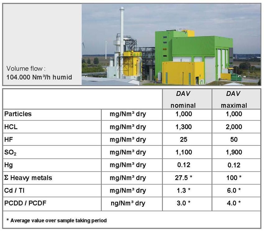
Rüdiger Margraf                                     Single and multi-stage procedures for the gas treatment
                                                                            downstream incineration plants
____________________________________________________________________________________________________________

1 Introduction

The dry and semi-dry chemisorption of acid crude gas components such as HF, HCl and
SOx, possibly with separation of dioxins / furans as well as Hg and/or Hg compounds and
other heavy metals, gained increasing importance with regard to the range of applications
of incineration plants. As a result of the further development of the sorption procedures
applied in this connection, this technology became an effective, reliable and cost-effective
alternative compared to e.g. the wet scrubbing system. In chapter 5 of the BVT-leaflet
concerning the best available technologies for waste incineration (July 2005) these
procedures are mentioned as best available technologies.

Table 1 shows the crude gas concentrations to be expected in the flue gas downstream
boiler for different types of fuels. The wide range to be covered makes clear, that regarding
the plant design and the additive powder selection, the plant constructor has to provide
individual concepts that are tailored to the special needs of the corresponding application.

        Fuel                           approx. range
                                       HCl [mg/Nm³ dry]                 SO2 [mg/Nm³ dry]
        Wood, grade A I - A IV         100 – 500                        100 – 500

        Sewage sludge                  < 100                            800 – 2,000

        Domestic waste                 750 – 2,500                      250 – 1,000

        RDF                            750 – 4,000                      500 – 3,000

       Tab. 1: Concentrations of acid crude gases for selected fuels

In the following different process technologies are introduced. Special emphasis lies in this
respect on the chemisorption of acid crude gas components. However, it should be
mentioned as reservation, that beside the presented variants, further alternative solutions
are available on the market, which are realised in practice.

________________________________________________________________________
Event of VDI Wissensforum
9 - 10 November 2009, Hamburg                                                                            3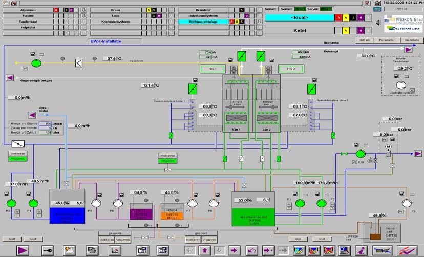
Rüdiger Margraf                                      Single and multi-stage procedures for the gas treatment
                                                                             downstream incineration plants
____________________________________________________________________________________________________________

2     Procedures with utilisation of Ca-containing additive powder qualities
2.1   Dry sorption with gas conditioning
2.1.1 Process description

The base variant is shown in illustration 1. It mainly comprises the units fabric filter and
additive powder injection device. To improve the efficiency, they are often completed by
the component parts reactor with particle re-circulation and evaporative cooler.

       Illustration 1: Dry sorption with gas conditioning

In principle commercially available calcium hydroxide, Ca(OH)2, with a specific surface of
approx. 18 up to 20 m2/g is injected into the flue gas flow upstream filter. As alternative
high-reactive Ca(OH)2 qualities with a specific surface of up to 40 m2/g with an at the same
time high pore volume > 0.2 cm³/g are available. The reaction equations as well as the
additive powder injection and remainder quantities at an additive powder efficiency of
100% are listed in table 2 below.

                                               Ca(OH)2 - injection         Resulting residual particle
                                            quantity related to crude      quantity (with crystal water
              Equations of reaction          gas at 100% conversion           content according to
                                                       (i=1)              experience) related to crude
                                                                                       gas
        2HF + Ca(OH)2 -> CaF2 + 2H2O                1.85    kg/kg                   1.95 kg/kg
        2HCl + Ca(OH)2 -> CaCl2 + 2H2O              1.01    kg/kg                   2.02 kg/kg
        SO3 + Ca(OH)2 -> CaSO4 + H2O                0.93    kg/kg                   2.15 kg/kg
        SO2 + Ca(OH)2 -> CaSO3 + H2O                1.16    kg/kg                   2.02 kg/kg

       Tab. 2: Reaction equations for Ca(OH)2

________________________________________________________________________
Event of VDI Wissensforum
9 - 10 November 2009, Hamburg                                                                             4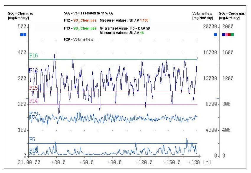
Rüdiger Margraf Single and multi-stage procedures for the gas treatment
downstream incineration plants
____________________________________________________________________________________________________________
In practice the additive powder has to be injected above-stoichiometric (normally 1.5 times
up to 3 times) in order to observe reliably the requested emission levels in the clean gas.
It is verifiable that especially in case of high additive powder recycle rates, the particle re-
circulation will lead to a clear improvement of the degree of separation for acid crude gas
components and/or to a reduction in the additive powder injection quantity.
The residence time of additive particles in the system is increased
Near reactor upstream filter there is a higher additive particle density (resulting
reaction time in reactor up to > 2 sec.)
Achievement of a frequent, spatial re-orientation of the re-circulated particulate with re-
deposition of the filter cake on the filter fabric
Due to the requested, necessary high particle recycle rates and in order to grant an
optimum additive powder efficiency, the utilisation of re-circulation systems becomes
necessary which can reliably handle considerable recycling quantities – even if larger
quantities of difficult particles, such as CaCl2, are present in the particle spectrum.
Illustration 2 shows a technology which has been applied successfully for many years for
various fields of application. It is characterised by high reliability and a homogeneous
distribution of the re-circulated particulate in the flue gas flow upstream filter. Conveying
with pneumatic methods, which is prone to frequent breakdowns, is not used.
Illustration 2: Conditioning Rotor – Recycle Process (KUV)
The following order of reaction results for the temperature range of 100°C and 220°C
typical for fabric filters:
SO3 > HF >> HCl >>> SO2
________________________________________________________________________
Event of VDI Wissensforum
9 - 10 November 2009, Hamburg 5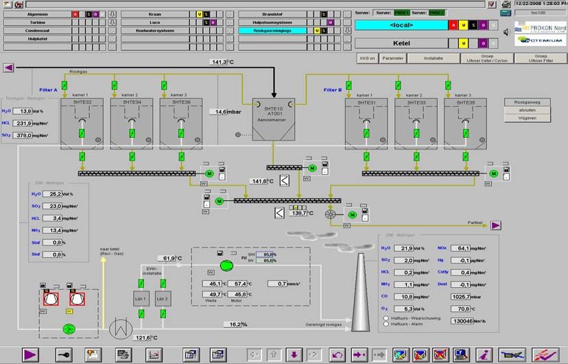
Rüdiger Margraf Single and multi-stage procedures for the gas treatment
downstream incineration plants
____________________________________________________________________________________________________________
The dry temperature as well as the absolute and relative humidity have a decisive
influence on the HCl and SO2 separation, however, the separation of SO3 and HF does not
present any problems within the stated temperature range. In order to save additive
powder, it is often useful to cool down the crude gas temperature upstream reactor to
optimal operating temperatures by means of recuperative heat exchange or preferably by
using an evaporative cooler. The min. admissible operating temperature has to be chosen
that way, that adhesion and blockages especially due to the hygroscopic characteristics of
the CaCl2 particles in the plant will be avoided. Illustration 3 shows the preferred
temperature range, depending on the dew point temperature.
Dew point temperature [°C]
70,0
Soliduslinie
Solidus line CaCl2*2H2O
65,0
Soliduslinie
Solidus line CaCl2*1H2O Area of formation of
60,0
calcium chloride preferred
Bereichsgrenz eA
limit of area A
solution operational
55,0
limit of area B
Bereichsgrenz eB area
50,0
45,0
40,0
35,0
30,0
25,0
20,0
20 30 40 50 60 70 80 90 100 110 120 130 140 150 160 170
Dry temperature [°C]
Reference: Dr. Mosch, Karpf
Illustration 3: Phase diagram CaCl2 x H2O
2.1.2 Application examples
This process variant is especially used for the gas treatment downstream incinerators for
wood grade A I – A IV. To support the separation efficiency, high-reactive Ca(OH)2 can be
used.
The application example described in illustration 4 clearly shows the evaporative cooler,
installed upstream filter. Based on the chosen process technology, a commercially
available Ca(OH)2 with low purchase costs can be used for this plant. The particle re-
circulation has in addition a positive effect on the consumption rates for activated coke,
which is injected for the separation of dioxins/furans and Hg as well as Hg-compounds.
________________________________________________________________________
Event of VDI Wissensforum
9 - 10 November 2009, Hamburg 6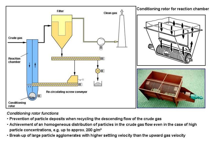
Rüdiger Margraf Single and multi-stage procedures for the gas treatment
downstream incineration plants
____________________________________________________________________________________________________________
Volume flow: 18.000 Nm³/h humid
Temperature upstream quench: 210 °C
Temperature upstream filter: 140 °C
Crude gas values downstream boiler:
Particles : 5.000 mg/Nm³ dry
HCl : 145 mg/Nm³ dry
HF : 20 mg/Nm³ dry
Ca(OH)2 HOK* SO2 : 195 mg/Nm³ dry
H2O +
PCDD/PCDF : 2 ng/Nm³ dry
Compressed air
Hg : 0,15 mg/Nm³ dry
from the
boiler Condi-
tioning Guarantee:
rotor
Reactor
KUV Particles : 10 mg/Nm³ dry
HCl : 10 mg/Nm³ dry
HF : 1 mg/Nm³ dry
SO2 : 50 mg/Nm³ dry
PCDD/PCDF : 0,1 ng/Nm³ dry
* Open-hearth
furnace coke
Hg : 0,03 mg/Nm³ dry
Illustration 4: Application example: Chemisorption with gas conditioning and particle re-circulation
downstream waste wood incinerator with grate bar firing
2.2 Chemisorption with particle conditioning and possibly gas conditioning
2.2.1 Process description
As described before and as a result of the increase in the absolute and relative humidity of
the flue gas, the gas conditioning has a positive effect on the sorption output. However, a
good additive powder efficiency, especially for the separation of SO2, can only be achieved
if the water steam partial pressure close to the recycled particulate lies at least for a short
time in the range of the saturation steam pressure. This will be achieved by using the
conditioned chemisorption with particle conditioning (illustration 5). Regarding this type of
process, the recycled particulate is wetted prior to reintroduction into the reactor. The
wetting causes an increase in the water steam content at the surface of the additive
powder particles, thus improving the reactivity in comparison to the acid crude gas
components.
Due to the limited proportional wetting of the recycled particulate and depending on the
gas temperature upstream reactor, it might be useful to install an upstream located
evaporative cooler for the adjustment of optimum reaction conditions.
________________________________________________________________________
Event of VDI Wissensforum
9 - 10 November 2009, Hamburg 7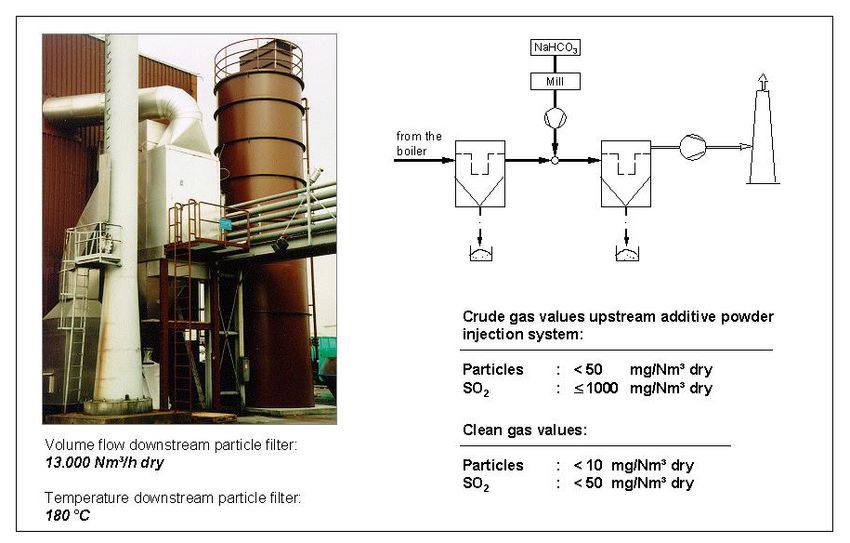
Rüdiger Margraf                                      Single and multi-stage procedures for the gas treatment
                                                                             downstream incineration plants
____________________________________________________________________________________________________________

       Illustration 5: Chemisorption with particle and gas conditioning

2.2.2 Application examples
2.2.2.1 Sludge incineration

The application example given in illustration 6, shows a sorption stage for the separation of
SO2 and Hg installed downstream of ESP for fly ash separation.

         Illustration 6: Application example: Sludge incineration

________________________________________________________________________
Event of VDI Wissensforum
9 - 10 November 2009, Hamburg                                                                             8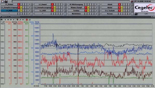
Rüdiger Margraf                                      Single and multi-stage procedures for the gas treatment
                                                                             downstream incineration plants
____________________________________________________________________________________________________________

Illustration 7 reflects the efficiency of the chosen technology on the basis of a record of
measuring values of a continuous SO2 crude gas and clean gas measurement over a
period of three hours. The indicated results have been achieved due to the utilisation of a
particle conditioning at a gas temperature downstream reactor of 120°C. A closer
approach of the temperature to the water dew point for the reliable observance of the
requested emission levels will not be necessary in this case.

         Illustration 7: SO2 separation at sludge incineration

2.2.2.2 Domestic waste incineration

Another example for the efficiency of the chemisorption with particle and gas conditioning
is the domestic waste incinerator shown in illustration 8. The requested limit values, mainly
in accordance with 17 BImSchV. can reliably be observed even in case of crude gas
contents for HCl of up to 2,000 mg/Nm³ and for SO2 up to 1,000 mg/Nm³ - in each case
indicated as DAV (illustration 9). The additive powder injection lies in this case at an
stoichiometric factor of 2.

________________________________________________________________________
Event of VDI Wissensforum
9 - 10 November 2009, Hamburg                                                                             9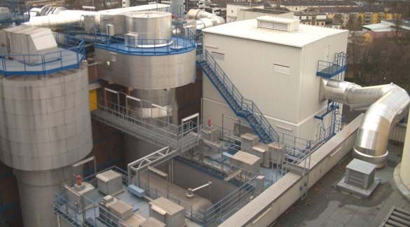
Rüdiger Margraf                                                                                                                                                                                             Single and multi-stage procedures for the gas treatment
                                                                                                                                                                                                                                    downstream incineration plants
____________________________________________________________________________________________________________

                                                                       5000                                                                                                                                                                      20

                                                                       4500
                                                                       4000
                                                                                          SO2 downstream boiler                                                                         HCl dow nstream boiler                                   18

                                                                       3500
                                                                       3000                                                                                                                                                                      16
         HCl -, SO2- cr u de g as, SO2- cl ean g as [ mg /Nm ³ dr y]

                                                                       2500
                                                                       2000                                                                                                                                                                      14

                                                                                                                                                                                                                                                        HCl-c lea n g a s, Sto ich io m et ry
                                                                       1500
                                                                       1000                                                                                                                                                                      12

                                                                        500
                                                                          0                                                                                                                                                                      10

                                                                       -500
                                                                       -1000                                                                                                                                                                     8

                                                                       -1500
                                                                                           SO2 stack                                                                    HCl stack
                                                                       -2000                                                                                                                                                                     6

                                                                       -2500
                                                                       -3000                                                                                                                                                                     4

                                                                       -3500
                                                                       -4000                                                                                                                                                                     2

                                                                       -4500                                            Stoichiometry
                                                                       -5000                                                                                                                                                                     0
                                                                          25. 05. 06   25 .05 .06   25 .05 .06   2 5.0 5.0 6   25 .05 .06   2 5.0 5.0 6   2 5.0 5.0 6   25. 05. 06   2 5.0 5.0 6   25 .05 .06   25. 05. 06   25 .05 .0 6   26 .05 .06
                                                                            00: 00      02 :00       04 :00        0 6:0 0      08 :00        1 0:0 0       1 2:0 0       14: 00       1 6:0 0      18 :00        20: 00      22 :00        00 :00

         Illustration 8: Conditioned dry sorption in MHKW Ludwigshafen

The conditioned dry gas cleaning system installed in 2004 replaced a definitely more
complex wet process, consisting of spray dryer, electrostatic precipitator, multi-stage
scrubber and aerosol separator (illustration 9).

         Illustration 9: Upgrading of MHKW Ludwigshafen from „wet“ to „conditioned dry“

________________________________________________________________________
Event of VDI Wissensforum
9 - 10 November 2009, Hamburg                                                                                                                                                                                                                                                                   10
Rüdiger Margraf Single and multi-stage procedures for the gas treatment
downstream incineration plants
____________________________________________________________________________________________________________
Up to the year 2008, another wet flue gas treatment plant had been operated in parallel at
the MHKW Ludwigshafen until its conversion in 2008, thus allowing a direct comparison of
both installed variants. Illustration 10 shows the average values of the year 2005 for
selected substances.
Verg leic h R R A t roc ken / n aß 20 05 MH K W L u d wig sh af en
50
Crude ga s v a lue s :
45
HCl 13 35 m g/ Nm ³
SO 2 30 3 m g/Nm ³
40
NO X 29 0 m g/Nm ³
Hum idity 1 3 %Vol.
35
30
Conce ntration
dry en
R RA 2 trock
25
wet
R RA 3 naß
20
15
10
5
0
H Cl SO2 Hg SDust
taub Cg es.
t otal N H3 NO2
C rude ga s com pone nt
Illustration 10: Comparison of gas cleaning systems „wet“ and „conditioned dry“ (2005)
The comparison shows that the conditioned dry sorption process is equal to the more
complex wet system. The only difference is the reference variable for the separation of the
acid crude gas components, i.e. SO2 for the scrubber and HCl for the conditioned dry
sorption.
The high degree of separation of SOx combined with a nearly 100 per cent SO3 sorption by
means of the conditioned dry sorption process allows the reduction of the operating
temperature of the downstream installed SCR plant from 300°C to 230°C.
An additional advantage as to the saving of energy costs is the higher gas temperature
upstream SCR stage of approx. 140°C.
It should be mentioned in addition, that compared to the spray sorption, an important
advantage of the conditioned dry sorption is the better degree of separation for SO2. This
is especially important in case of downstream installation of SCR plants.
________________________________________________________________________
Event of VDI Wissensforum
9 - 10 November 2009, Hamburg 11Rüdiger Margraf Single and multi-stage procedures for the gas treatment
downstream incineration plants
____________________________________________________________________________________________________________
2.3 Conditioned dry sorption with graded additive powder injection
2.3.1 Design variants
In case of increasing crude gas values for HCl and SO2, the stoichiometry of basic variant
of the conditioned dry sorption has to be increased partly definitely above a typical base
value of 2 without any additional measures in order to observe reliably the emission limit
values. At rising crude gas values it will therefore be advisable to apply a graded additive
powder injection, thus using in addition the reaction chamber of evaporative cooler / spray
absorber when indicated. Illustration 11 shows different, corresponding process variants.
For all concepts, the main quantity of additive powder is injected into the reactor
downstream evaporative cooler in the nominal case. The injection of additive powder
upstream or within evaporative cooler / spray absorber mainly serves for the corrosion
protection as well as for the smoothening of crude gas peaks.
Illustration 11: Conditioned dry sorption with graded additive powder injection
2.3.2 Application examples for RDF incinerations
The separation potential is exemplary shown in illustration 12 by means of a gas cleaning
system downstream RDF incinerator. In this case the additive powder injection takes place
in steps, using NaOH in the evaporative cooler and Ca(OH)2 in the reactor of conditioned
dry sorption. At mean crude gas values for HCl of 1,800 up to 2,500 mg/Nm³ as well as
1,000 up to 1,500 mg/Nm³ for SO2, combined with definitely higher crude gas peaks for
both crude gases, the limit values of 17 BImSchV. will reliably be undercut with at the
same time acceptable additive powder consumption.
________________________________________________________________________
Event of VDI Wissensforum
9 - 10 November 2009, Hamburg 12Rüdiger Margraf Single and multi-stage procedures for the gas treatment
downstream incineration plants
____________________________________________________________________________________________________________
Illustration 12: Gas cleaning with graded additive powder injection downstream RDF incinerator
Illustration 13 shows the RDF heat-and-power-station Stavenhagen as representative for
several realised plants and illustration 14 presents some trend curves from the control
system of this plant as result for the separation efficiency.
The average stoichiometric factor actually reached in continuous operation has repeatedly
been determined by means of remainder analyses. It lies in a range of 1.8 up to 2.0. The
chloride content in the remainder totals to approx. 20 up to 22 % thus lying in a range
noncritical for the product handling.
Illustration 13: RDF HKW Stavenhagen
________________________________________________________________________
Event of VDI Wissensforum
9 - 10 November 2009, Hamburg 13Rüdiger Margraf Single and multi-stage procedures for the gas treatment
downstream incineration plants
____________________________________________________________________________________________________________
Temperature crude gas Volume flow clean gas
Temperature clean gas Humidity crude gas
SO2 crude gas
HCl crude gas
SO2 clean gas HCl clean gas
Hg clean gas
Illustration 14: Trend curves crude/clean gas values, temperatures, gas humidity and volume flow
2.4 Concepts for low emission limit values, considering NOx
2.4.1 Preliminary remark
Since a couple of months, increased discussions are hold on the European scale
concerning a tightening of the emission limit values. In this connection, e.g. the request
for a NOx limit value of < 100 mg/Nm³ dry with at the same time limitation of NH3 slippage
is being discussed. Operating results gathered from modern incineration plants with
SNCR procedures for the NOx reduction demonstrated that in most of the cases the
reliable observance of the tightened NOx limit value of 100 mg/m³ will be possible. Even
in case of requested lower NOx emission limit values, the installation of a catalyst is not
imperative. Also in this case a SNCR procedure can be applied, but then a further
separation stage for NH3 has possibly to be integrated in the concept, depending on the
max. admissible NH3 slippage.
2.4.2 Application example SNCR with NH3 separation
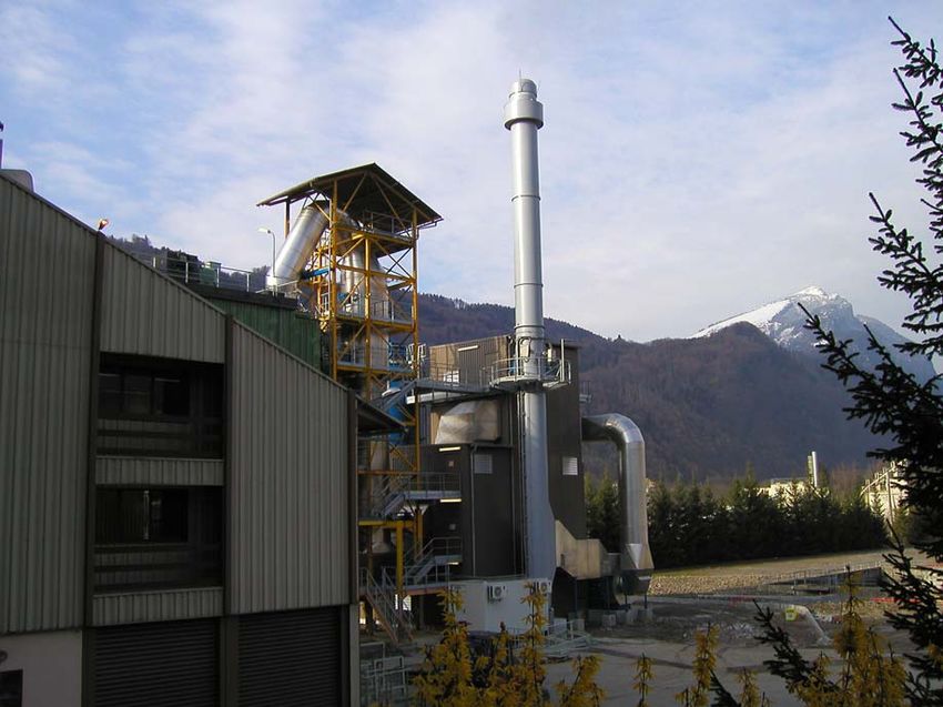
Illustration 15 shows an example for a gas cleaning system downstream circulating vortex
bed for biomass combustion in the Netherlands. In order to observe the requested NOx
limit value of 70 mg/m³, the constructor of boiler installed a SNCR plant. The NH3 slippage
downstream boiler is limited to max. 15 mg/m³. In addition to this, illustration 15 shows a
table with the requested emission limit values to be observed by means of the downstream
installed gas cleaning system.
________________________________________________________________________
Event of VDI Wissensforum
9 - 10 November 2009, Hamburg 14Rüdiger Margraf Single and multi-stage procedures for the gas treatment
downstream incineration plants
____________________________________________________________________________________________________________
The following concept has been chosen for this gas cleaning system:
Cyclones for separate fly ash removal
Conditioned dry sorption at approx. 150° C
Heat exchanger for cooling down of gases to approx. 100°C
Wet ESP with integrated acid and basic stage
Emission li mit values DAV HAV AAV
Particles content, total mg/Nm³ dry 3 15 1
HCl cont ent mg/Nm³ dry 5 60 3
HF content mg/Nm³ dry. 0,5 4 0,2
SO2 content mg/Nm³ dry 30 200 10
NH3 content mg/Nm³ dry 5 5
Hg content mg/Nm³ dry 0,03 0,005
Cd content mg/Nm³ dry 0,005
TI content mg/Nm³ dry 0,005
Cd and TI content mg/Nm³ dry 0,051) 0,01
2)
Sb - Sn content, total mg/Nm³ dry 0,251) 0,05
Dioxin /Fu ran content TEQ ngN/m³ dry 0,051) 0,02
1)
Average value over sample t aking period
2) Sum Sb - Sn : Sb + As + Pb + Cr + Co + Cu + Mn + Ni + V + Sn
• Vo lume flow :
105.000 Nm³/h humid
Illustration 15: Gas cleaning downstream biomass combustion HVC, Alkmaar/ Netherlands
In addition to an integrated NH3 separation, this concept also offers the reliable
observance of extremely low emission values in a cost-effective way
Illustration 16 shows the structure of this plant, based on the scheme taken from the
process control system. The wet stage downstream conditioned dry sorption serves for the
reliable undercut of all requested emission limit values.
________________________________________________________________________
Event of VDI Wissensforum
9 - 10 November 2009, Hamburg 15Rüdiger Margraf Single and multi-stage procedures for the gas treatment
downstream incineration plants
____________________________________________________________________________________________________________
Illustration 16: Schematic view of gas cleaning system for biomass combustion HVC, Alkmaar/
Netherlands
The NH3 separation takes place in the acid scrubbing stage (illustration 17) which is
installed upstream of wet ESP. The pH-value of this stage is adjusted to approx. 5.6. In
order to grant a sufficient SO2 separation, a ph-value of 6.1 has been chosen for the
second scrubbing stage.
Illustration 17: Schematic view of wet ESP with integrated two-stage scrubbing process
________________________________________________________________________
Event of VDI Wissensforum
9 - 10 November 2009, Hamburg 16Rüdiger Margraf Single and multi-stage procedures for the gas treatment
downstream incineration plants
____________________________________________________________________________________________________________
The waste water from the basic scrubbing stage is reused in the humidifying mixers for the
conditioned dry sorption. The NH3-laden water from the acid stage (max. approx. 0.5 m³/h)
is directed towards a central water processing of location.
3 Dry sorption with utilisation of NaHCO3
3.1 General design, advantages and disadvantages
The dry sorption with NaHCO3 is competing with process technologies using Ca-containing
additive powder qualities. The quite simple process technology of the basic variant is
shown in illustration 18. The additive powder is pulverised and injected into the gas flow
upstream filter. In case of crude gas temperatures of > 150°C, a thermal activation of
sodium hydrogen carbonate will take place which becomes quicker with rising
temperatures. The result is a high reactive sodium carbonate. The reaction time from
injection point of additive powder until the arrival at the filter fabric should last at least 2
sec.
Illustration 18: Basic variant of dry sorption with NaHCO3
________________________________________________________________________
Event of VDI Wissensforum
9 - 10 November 2009, Hamburg 17Rüdiger Margraf Single and multi-stage procedures for the gas treatment
downstream incineration plants
____________________________________________________________________________________________________________
Tab.3 shows the chemical reaction equations as well as the injection and remainder
quantities on the basis of an additive powder efficiency of 100%. Normally the required
emission limit values are reliably achieved in continuous operation with the adequate plant
design with an over stoichiometric factor of 1.2 – max. 1.5. Especially in case of
temperatures lower than 160°C, the multiple re-circulation of the particles separated in the
filter into the flue gas flow upstream filter can be advantageous.
Tab. 3: Reaction equations for NaHCO3
The main advantages of this technology are:
High reactivity of additive powder
Simple plant design
Remainder quantity is reduced compared to the additive powder injection (advantage in
case of high disposal costs)
Lower hygroscopic nature of resulting salts
The facing disadvantages are:
Unfavourable mass ratio of additive powder to crude gas
Necessary pulverisation of additive powder prior to injection into the flue gas flow
High specific purchase costs of the additive powder
As alternative there are further additive powder qualities on sodium basis available, such
as e.g. Na2CO3 or NaOH. These additive powder qualities, however, will not be taken into
consideration in the context of this lecture.
________________________________________________________________________
Event of VDI Wissensforum
9 - 10 November 2009, Hamburg 18Rüdiger Margraf Single and multi-stage procedures for the gas treatment
downstream incineration plants
____________________________________________________________________________________________________________
3.2 Application examples
3.2.1 Tyre combustion
The plant example shown in illustration 18 demonstrates the advantages of this type of
process. The complexity of equipment for achieving a degree of separation of SO2 > 95 %
is very low. A fabric filter with corresponding additive powder injection has been installed
downstream existing filter for fly ash separation. A particle conditioning is not used.
Illustration 19: Application example tyre combustion
3.2.2 Domestic waste incineration
Illustration 20 shows an application example for a gas cleaning plant downstream
domestic waste incinerator. Compared to the basic variant shown in illustration 18, this
plant is additionally provided with an evaporative cooler for the adjustment of the gas
temperature as well as with a particle re-circulation.
In 2009 extensive examinations have been realised at this plant in order to determine the
influence of operating temperature and particle re-circulation on the additive powder
consumption. Whereas temperatures in a range between 150°C and 180°C do only have a
very low, hardly recognisable influence, the operation with and without particle re-
circulation shows a considerable difference. Illustration 21 clearly shows the influence of
the particle re-circulation. In case of an adequately dimensioned plant and integration of a
particle re-circulation system, stoichiometrics of < 1.2 can reliably be kept in continuous
operation.
________________________________________________________________________
Event of VDI Wissensforum
9 - 10 November 2009, Hamburg 19Rüdiger Margraf Single and multi-stage procedures for the gas treatment
downstream incineration plants
____________________________________________________________________________________________________________
NaHCO3
Mill HOK*
H2O
from
ESP Cond.
rotor
reactor
KUV
* Open-hearth
furnace coke
Crude gas values :
Particles : 90 mg/Nm³ dry
HCl : 1200 mg/Nm³ dry
HF : 20 mg/Nm³ dry
SO2 : 300 mg/Nm³ dry
Volume flow : PCDD/PCDF : 3 ng/Nm³ dry
34.000 Nm³/h humid Hg : 0,4 mg/Nm³ dry
Temperature upstream quench : Guarantee :
250 °C
Particles : 10 mg/Nm³ dry
HCl : 10 mg/Nm³ dry
HF : 1 mg/Nm³ dry
SO2 : 50 mg/Nm³ dry
PCDD/PCDF : 0,1 ng/Nm³ dry
Hg : 0,05 mg/Nm³ dry
Illustration 20: Application example: Domestic waste incinerator
dP filter: 11 - 12 mbar - Volume flow: 26,500 Nm³/h dry - Additive powder dosage: 35 kg/h (Min. quantity) - i calculated from current filter discharge
21.07.09 IRH Cluses
Temp. downstr. quench 150°C Temp. downstr. quench 150°C
Re-circulation 90 % until 10:30 as of 10:30 Re-circulation 10 %
1500 50
1350
1200 45
1050
900 40
HF crude gas, HCl stack SO2 stack, HF stack
750
600 35
HCl crude gas, SO2 crude gas
450
300 30
150
0 25
-150
i=1.11 i=1.17 i=1.12 i=1.24 i=1.44 i=1.36
-300 20
-450
-600 15
-750
-900 10
-1050
-1200 5
-1350
-1500 0
00:00 02:00 04:00 06:00 08:00 10:00 12:00 14:00 16:00 18:00 20:00 22:00 00:00
Time
HCl crude gas mg/Nm³ dry SO2 crude gas mg/Nm³ dry HF crude gas mg/Nm³ dry
I HCl stack mg/Nm³ dry SO2 stack mg/Nm³ dry HF stack mg/Nm³ dry
llustration 21: Influence of particle re-circulation on the additive powder consumption
________________________________________________________________________
Event of VDI Wissensforum
9 - 10 November 2009, Hamburg 20Rüdiger Margraf Single and multi-stage procedures for the gas treatment
downstream incineration plants
____________________________________________________________________________________________________________
4 Process selection
The introduced examples of process technologies only reflect a selection of concepts that
have been realised for the gas treatment downstream incinerators for waste, RDF, sludge
or biomass. Independent of this, from the author’s point of view, with regard to the design
of new plants, the conditioned dry sorption with utilisation of Ca(OH)2/CaO and the dry
sorption with NaHCO3 gained an outstanding position in the last years in Germany and
became accepted especially when compared to wet systems. Due to the corresponding
requirements and conditions of the separate applications, it will be necessary to adjust the
base variant from case to case by means of complementary measures or also by
additional separation stages.
This introduction of process technologies did not include a comparative assessment as
this has to take place on a project-related basis. All systems have their strengths and
weaknesses. There is no most suited procedure for all types of applications.
Each application has to be considered separately. Criterions of choice for the assessment
are:
Requested degrees of separation (nominal and max. values as well as peaks)
Emission limit values
Investment costs
Operating costs as e.g. additive powder supply and disposal as well as energy costs
for power and compressed air
Costs for maintenance and repair
Plant availability and reliability of operation
Part load behaviour
Flexibility with regard to changing crude gas values, emission limit values and specific
operating costs
________________________________________________________________________
Event of VDI Wissensforum
9 - 10 November 2009, Hamburg 21Rüdiger Margraf Single and multi-stage procedures for the gas treatment
downstream incineration plants
____________________________________________________________________________________________________________
Enzer Straße 26
31655 Stadthagen
GERMANY
Phone: +49 5721 708 - 200
Fax: +49 5721 708 – 154
E-Mail: info@luehr-filter.com
Internet: www.luehr-filter.com
________________________________________________________________________
Event of VDI Wissensforum
9 - 10 November 2009, Hamburg 22You can also read