Mechanical Effect of Performance Pressure Boots on Cadaveric Equine Hindlimb Fetlock Biomechanics - MDPI
←
→
Page content transcription
If your browser does not render page correctly, please read the page content below
animals
Article
Mechanical Effect of Performance Pressure Boots on Cadaveric
Equine Hindlimb Fetlock Biomechanics
Jennifer Symons

                                          Shiley School of Engineering, University of Portland, Portland, OR 97203, USA; symons@up.edu;
                                          Tel.: +1-503-943-7435

                                          Simple Summary: Pressure boots are performance enhancing equipment used by showjumping
                                          horses. Showjumping is scored by knocked down obstacle rails and time. Similar to weighted
                                          boots, pressure boots are intended to improve the hindlimb retraction of jumping horses to reduce
                                          the likelihood of knocking down rails on course. Manufacturers describe pressure boots as using
                                          acupressure to improve a horse’s awareness of their own limbs. However, this mechanism has not
                                          been verified within the scientific literature. The size and shape of features on the interior boot
                                          surface suggest a mechanical mechanism may affect anatomical structures within the lower limb.
                                          This research aims to characterize the mechanical effect of pressure boots by measuring forces and
                                          joint angles of cadaveric limbs with and without a pressure boot applied. Cadaveric limbs with a
                                          pressure boot applied required greater compressive loads to flex the fetlock joint than limbs without
                                          a pressure boot applied. This difference in compressive loads increased with increasing fetlock
                                          flexion angle. Differences in limb compressive loads contributed to greater tensile loads of palmar
                                          tendons and ligaments, specifically the suspensory apparatus. Greater tensile loading of tendons
                                and ligaments may increase the likelihood of musculoskeletal injury and warrant concern for animal

                                          welfare of equine showjumping athletes.
Citation: Symons, J. Mechanical
Effect of Performance Pressure Boots
                                          Abstract: Pressure boots are applied to hind limbs of showjumping horses with the intent to enhance
on Cadaveric Equine Hindlimb
                                          jumping form. Manufacturers claim acupressure points enhance proprioception of hind limbs.
Fetlock Biomechanics. Animals 2021,
                                          With this increased awareness, horses are expected to retract their hind limbs to clear jump rails.
11, 958. https://doi.org/10.3390/
ani11040958
                                          This research aimed to investigate a more direct, mechanical effect of pressure boots on hind limb
                                          biomechanics. Cadaveric hind limbs (n = 6) were mechanically loaded in axial compression (3 cycles
Academic Editors: Jane M. Williams        at 0.25 Hz, displacement control ~3300 N) with (2 trials) and without (2 trials) a pressure boot applied.
and Gillian Tabor                         During mechanical loading, fetlock angle was measured using bone fixed pins with retroreflective
                                          markers (30 Hz). Changes in limb load and fetlock angle between unloaded and loaded states, as
Received: 19 January 2021                 well as average fetlock joint stiffness, were compared between trials with and without the pressure
Accepted: 26 March 2021                   boot via ANOVA. Differences in measured loads between trials with and without the boot were
Published: 30 March 2021                  observed in both unloaded (∆ = 6 N, p = 0.05) and loaded states (∆ = 25 N, p = 0.002). Trials with
                                          the boot had greater average fetlock stiffness (∆ = 3 N/degree, p = 0.001). Differences in loads with
Publisher’s Note: MDPI stays neutral      and without boots may increase with greater fetlock angles when cantering and jumping. These
with regard to jurisdictional claims in
                                          mechanical effects of pressure boots may contribute to greater tensile loading of palmar tendons and
published maps and institutional affil-
                                          ligaments, and likelihood of musculoskeletal injury that can be related to animal welfare issues.
iations.

                                          Keywords: horse; metatarsophalangeal joint; suspensory ligament; jumping; pressure boots; pinch; flick

Copyright: © 2021 by the author.
Licensee MDPI, Basel, Switzerland.
                                          1. Introduction
This article is an open access article
distributed under the terms and
                                               Equine athletes in many disciplines undergo rigorous training. This training is neces-
conditions of the Creative Commons
                                          sary to maximize horses’ potential to perform well in competition. Horse owners, riders,
Attribution (CC BY) license (https://     and trainers implement many different strategies to maximize performance in equine
creativecommons.org/licenses/by/          athletes. Strategies may include nutrition, stabling environment, veterinary treatments,
4.0/).

Animals 2021, 11, 958. https://doi.org/10.3390/ani11040958                                                 https://www.mdpi.com/journal/animals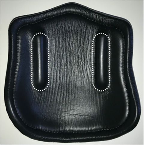
Animals 2021, 11, 958                                                                                           2 of 9

                        physiotherapy, massage, chiropractic work, acupuncture, training practices, arena surface
                        management, shoeing, and equipment/tack choices.
                              Within showjumping, the design of distal limb coverings has been used to influence
                        equine athlete performance, particularly hindlimb boots. Past studies have demonstrated
                        the ability of boots to alter equine limb biomechanics. Several different types of limb
                        coverings have been shown to decrease the amount of fetlock dorsiflexion during forelimb
                        loading [1,2]. Additionally, weighted boots have been shown to alter the speed and degree
                        of hindlimb retraction [3,4].
                              Prior research findings have supported the implementation of several rules regulating
                        the design and use of distal limb coverings in equestrian competition. Within the past
                        several years, both the FEI (Fédération Équestre Internationale) and United States Eques-
                        trian Federation (USEF) have implemented rule changes narrowing hind boot designs
                        permitted in showjumping competitions [5,6]. These changes outline boot weight, dimen-
                        sions, interior surface, strap compliance, and fastener types. Within the FEI, these rules
                        were first applied to all horse and rider age-restricted classes. USEF hind boot rules were
                        only applied to horse age-restricted classes, specifically young jumper classes (ages 5–8).
                        The FEI recently extended these rules to all classes [5]. However, USEF presently has no
                        reported plans to extend these rules to additional classes.
                              Several years ago, pressure boots were designed as an alternative to weighted boots
                        that had been banned. These performance enhancing boots anecdotally produce similar
                        increased limb retraction to clear obstacles in showjumping. Pressure boots incorporate
                        protrusions on the medial and lateral interior surfaces of each boot. Manufacturers describe
                        these protrusions as pushing on acupressure points intended to improve proprioception
                        of the limb. Unfortunately, no prior published research has verified this proposed neu-
                        ral mechanism.
                              Similar to weighted boots, pressure boots are not permitted within FEI and USEF rules
                        governing open, rider and/or horse age-restricted classes. However, pressure boots are
                        permitted in open classes within USEF, whereas weighted boots are not permitted in open
                        classes within either governing bodies. Rule changes related to hind boots have received
                        mixed support from riders and trainers globally. The gradual implementation of hind boot
                        rules within competition brings into question whether public opinion within the industry
                        will influence these rules being broadened or narrowed in the future.
                              The use of performance enhancing equipment within equestrian sports spurs concerns
                        of both unfair advantage in competition and animal welfare associated with possible
                        musculoskeletal injury of strained tendons and ligaments during training and competition.
                        Existing rules that restrict performance enhancing boots in horse and rider age-restricted
                        classes may address both concerns in competition, but do not address the possibility of
                        animal welfare issues during training. While the competitive advantage of performance
                        enhancing equipment may be debated by riders in open classes, the lack of restrictions in
                        some open classes fails to universally protect the welfare of all equine athletes.
                              The size and placement of protrusions on the interior surface of pressure boots may
                        affect palmar fetlock musculoskeletal structures, like the suspensory apparatus. This study
                        aimed to investigate the mechanical effect of pressure boots on fetlock biomechanics in the
                        absence of neural influences, including nociception and proprioception. Pressure boots
                        were hypothesized to alter joint stiffness as it pertains to fetlock dorsiflexion and loading
                        of palmar elastic energy storing tendons and ligaments. Specifically, limbs with a pressure
                        boot applied were expected to have greater fetlock stiffness and require greater compressive
                        loads to flex the fetlock joint compared to limbs without a pressure boot applied. Changes
                        in fetlock stiffness and preferential increased loading of musculoskeletal structures may
                        affect risk of injury, which has the potential to negatively impact animal welfare.

                        2. Materials and Methods
                            Hindlimbs from cadavers of 6 horses were used in this study. Known horse ages
                        ranged from 2 to 6 years (Table 1). Limbs were provided through a donation program that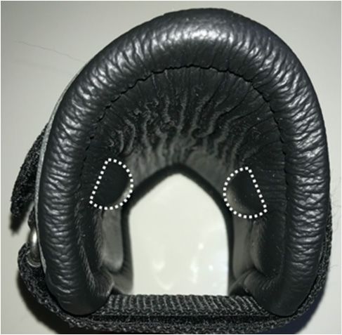
Animals 2021, 11, 958 3 of 9
accepts racehorses and pleasure riding horses after euthanasia. Horses had no diagnosed
hindlimb musculoskeletal injuries when euthanized. No gross structural defects were
observed in any study limbs. Racehorses donated typically range in age from 2 to 8 years,
whereas pleasure horses donated are of adult to senior age. While study limbs differed in
age and/or size compared to limbs of typical showjumping horses, all study limbs had
normal, intact, distal limb anatomical structures of interest in this study. Limb sidedness
(left or right) was assigned randomly to each horse, while ensuring an equal number of
each limb side.
Table 1. Horse age, breed, cadaver limb side, and starting condition.
Horse Age (years) Breed Hindlimb Starting Condition
1 2–3 TB L Without boot
2 6 TB R Without boot
3 unknown TB R Without boot
4 unknown Pleasure L With boot
5 unknown TB L With boot
6 unknown Pleasure R With boot
Each cadaveric limb was dissected of all muscles proximal to the point of the hock.
Dissection of these muscles altered the proximal attachments of the superficial and deep
digital flexor tendons that cross the fetlock. The lack of muscle activations and disruption
of proximal attachment sites altered fetlock stiffness in cadavers compared to live horses.
However, these alterations were uniform throughout all subsequent mechanical tests with
and without a pressure boot applied.
Each tibia was cut approximately 11 cm proximal to the point of the hock to facilitate
casting of the distal tibia in polymethyl methacrylate using a cylindrical mold. Spherical
motion capture markers (n = 14, 13 mm diameter) were mounted to each limb via a series
of bone mounted fixation pins (n = 8). Transcortical mediolateral pins were placed at the
proximal aspect of the third metatarsal bone, as well as the first and second phalanges.
Lateral pins were placed at the distal aspect of the third metatarsal bone and first phalanx, as
well as the hoof. Dorsal pins were placed at the distal aspect of the second phalanx and hoof.
Pin and marker placement relative to anatomical structures were recorded via dorsopalmar
and lateral radiographs with a calibration marker (70 kVp, 2 mAs). Protrusions on the
interior surface of the pressure boots were positioned 6 cm proximal from a depression
intended to wrap around the point of the fetlock (i.e., ergot or tuft of hair). Distance
between the junction of the suspensory ligament and suspensory branches, and the point
of the fetlock was measured to relate boot morphology (i.e., protrusion size and location)
to limb anatomy.
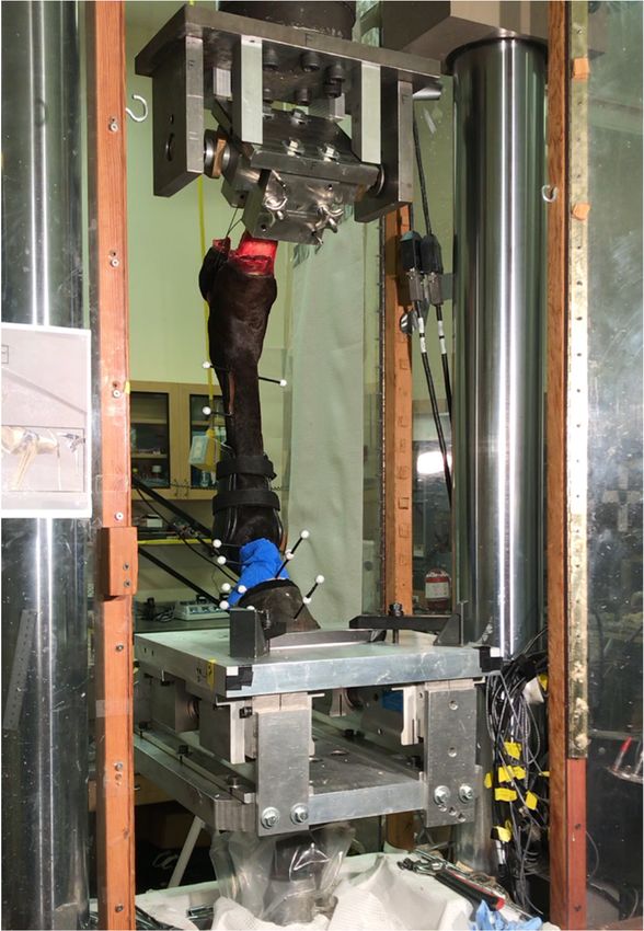
Each cadaveric limb was mounted proximally in a material testing system (MTS) using
a custom clamping fixture (Figure 1). The fixture angle (i.e., tibial orientation) was 38◦
caudal from vertical, which was informed by previous published kinematics data [7] and
institutional lab knowledge of prior mechanical testing setups. To fix the hock angle in the
absence of palmar muscle tendon units, the calcaneus was tethered to the proximal fixture.
Skin and superficial soft tissues were removed from the medial and lateral aspects of the
calcaneus to drill a mediolateral hole through this bone. Aircraft cable was then threaded
through this bone hole, as well as through a hole in the proximal fixture, and tightened
until the third metatarsal bone was roughly 5◦ caudal from vertical. This initial caudal
position was needed to allow for some settling during preconditioning that would achieve
vertical orientation prior to mechanical testing trials.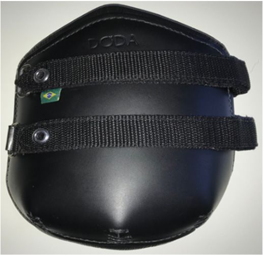
Animals 2021, 11, 958 4 of 9
Animals 2021, 11, x 4 of 9
Figure1.1.Cadaveric
Figure Cadavericlimbs
limbswere
weretransected
transectedat atthe
the middle
middle of
of the
the tibia
tibia and
and mounted
mounted proximally
proximally in
in aa
material testing system. The distal steel platform allowed for craniocaudal translation during limb
material testing system. The distal steel platform allowed for craniocaudal translation during limb
loading. Motion capture markers were mounted to bone fixed pins in the third metatarsal bone,
loading. Motion capture markers were mounted to bone fixed pins in the third metatarsal bone, first
first and second phalanges, as well as the hoof.
and second phalanges, as well as the hoof.
Distally within the MTS, the hoof was placed directly onto a steel platform that was
Distally within the MTS, the hoof was placed directly onto a steel platform that was
able to translatecranially
able to translate cranially and
and caudally
caudally during
during limb
limb loading.
loading. AAtoe toeblock
blockwaswasmounted
mountedin
front of the hoof to prevent translation of the hoof relative to the
in front of the hoof to prevent translation of the hoof relative to the platform. Initial platform. Initial com-
pressive loading was controlled manually (i.e., not controlled by
compressive loading was controlled manually (i.e., not controlled by computer) up to computer) up to 1800 N.
EachN.limb
1800 Each was then
limb waspreconditioned for 200 for
then preconditioned cycles200atcycles
0.25 Hz fromHz
at 0.25 approximately 500 N to
from approximately
500 N to 1800 N (displacement controlled by computer, ∆d unique to each limb).precon-
1800 N (displacement controlled by computer, Δd unique to each limb). After this After
ditioning,
this each thirdeach
preconditioning, metatarsal bone maintained
third metatarsal a verticala orientation
bone maintained under allunder
vertical orientation loads
greater than 500 N. Compressive loading was then manually increased
all loads greater than 500 N. Compressive loading was then manually increased to 3300 N to 3300 N (approx-
imate peak load
(approximate peakatload
walk).
at walk).
Eachlimb
Each limbwas
wastested
testedforfor44trials,
trials,while
whilealternating
alternatingconditions
conditionswith withand
andwithout
withouta a
pressureboot
pressure boot(Doda
(DodaJumping
JumpingBoots BootsModel
ModelI,I,Mikmar
MikmarBit BitCompany,
Company,Divide,
Divide,CO,CO,USA;
USA;
Figure 2) between each trial (2 trials with boot and 2 trials without boot).
Figure 2) between each trial (2 trials with boot and 2 trials without boot). The pressure boot The pressure
boot
was was applied
applied manually
manually by aoperator
by a single single operator
who waswho was with
familiar familiar
theirwith theirappropriate
use and use and ap-
propriate strap tension on live horses. Each trial consisted of 3 cycles
strap tension on live horses. Each trial consisted of 3 cycles at 0.25 Hz from approximately at 0.25 Hz from ap-
proximately
400 N to 3300 400 N to 3300 N (displacement
N (displacement controlled
controlled controlled controlled∆d
by computer, by unique
computer, Δd unique
to each limb).
to each limb).load
Compressive Compressive
and strokeload andMTS,
of the strokeasofwell
the as
MTS, as well as three-dimensional
three-dimensional motion capture mo-
tion capture
video via two video via two
high-speed, high-speed, high-resolution
high-resolution cameras (Fastcam cameras (FastcamTokyo,
PCI, Photron, PCI, Photron,
Japan)
Tokyo, Japan)
oriented orientedand
dorsomedially dorsomedially
dorsolaterally,andwere
dorsolaterally,
collected atwere 30 Hz.collected at 30 Hz.Animals 2021, 11, 958 5 of 9
Animals 2021, 11, x
(a) (b) (c)
Figure 2. Pressure
Figureboot: (a) Bootboot:
2. Pressure exterior flat,exterior
(a) Boot (b) Bootflat,
interior flat,interior
(b) Boot (c) Bootflat,
interior folded.
(c) Boot Protrusions
interior (1 cm × 1.5 cm × 8.5
folded. Protrusions
cm, dotted outlines) were located roughly 8.5 cm from the distal edge of the boot and 3.5 cm
(1 cm × 1.5 cm × 8.5 cm, dotted outlines) were located roughly 8.5 cm from the distal edge of palmar from thethe
medial and
lateral leading edges of the boot.
boot and 3.5 cm palmar from the medial and lateral leading edges of the boot.
Motion capture Motion
videos capture videos were
were processed usingprocessed
motion using
analysismotion analysis
software software
(Motus, Vicon(Motus, V
Motion Systems,Motion Systems,
Oxford, UK).Oxford, UK). Discrepancies
Discrepancies between pin/markerbetween pin/marker
positions positions
and boneand bone
gitudinal
longitudinal axes wereaxes were accounted
accounted for by usingfor by usingmarkers
virtual virtual markers
based on based on radiographic m
radiographic
measurements. Fetlock joint angles were filtered using a 3 Hz lowpass, Butterworth filter.
urements. Fetlock joint angles were filtered using a 3 Hz lowpass, Butterworth
filter. Duringing
thethe 3 cycles
3 cycles within
within each
each trial,
trial, 3 maximum
3 maximum loads
loads were
were recorded,asaswell
recorded, wellasas 2 mini
loads. Limb
2 minimum loads. Limb loading loading and unloading
unloading were each observed twice within thesemaximum
were each observed twice within these
maximum and minimum
minimumloads loadsrecorded
recordedduring
duringeacheachtrial.
trial. Typically, stiffness of
Typically, torsional stiffness of a joint
ported
a joint is reported asas
thethe change
change inin angle(◦(°)
angle ) ininresponse
responsetotoan anapplied
appliedtorque
torque(Nm).
(Nm). The The testing s
allowedfor
testing setup allowed forananaccurate
accurate measure
measure of load
of load applied
applied tolimb,
to the the limb,
but did butnot
did not allow f
allow
for an accurateaccurate
measuremeasure of changing
of changing moment arm momentduring armlimb during
loading limb loading torque.
to calculate to calculate to
Therefore,
Therefore, fetlock fetlock
stiffness stiffness was
was reported as thereported
ratio of as the ratio
change of change
in load to changein load to change in fe
in fetlock
angle during angle during or
limb loading limb loading or
unloading. unloading.
Loads, Loads,and
joint angles, jointfetlock
angles,stiffnesses
and fetlock werestiffnesses
statistically compared (p =compared
statistically 0.05) between trialsbetween
(p = 0.05) with and without
trials with aand
pressure
without boot applied boot ap
a pressure
using a one-wayusingANOVA
a one-way (PROC
ANOVA MIXED,
(PROC SASMIXED,
Institute,SAS Cary, NC, USA)
Institute, Cary, to NC,allow
USA)for to allow fo
repeated measures
peated within each within
measures subject.each
Fixed effects Fixed
subject. included condition
effects included (with and without
condition (with and wi
boot), as wellboot),
as theasinteraction
well as theof conditionofand
interaction horse. and
condition Duehorse.
to theDue smallto sample
the small size,
sample siz
assumptions of the ANOVA were satisfied by visual assessment of residual
sumptions of the ANOVA were satisfied by visual assessment of residual distributio distribution.
3. Results 3. Results
Changes in fetlock
Changesangle and load
in fetlock during
angle and cadaveric
load during distal hindlimb
cadaveric compression
distal hindlimb compre
within a material testing system (MTS) were compared between
within a material testing system (MTS) were compared between trials trials with andwith
trials
and trials
without a pressure boot applied. Results from one cadaveric limb (Horse 1) were
out a pressure boot applied. Results from one cadaveric limb (Horse 1) were removed removed
due to hoof translations with respect
to hoof translations to the
with steelto
respect platform in platform
the steel the absence in of
thea absence
toe block.ofAll
a toe block
reported results reflect the remaining five limbs.
reported results reflect the remaining five limbs.
No statistically significant differences were observed in fetlock angle between trials
No statistically significant differences were observed in fetlock angle between
with and trials without the pressure boot (Table 2). However, statistically significant
with and trials without the pressure boot (Table 2). However, statistically significan
differences were observed in the load measured by the MTS. Trials with the pressure boot
ferences were observed in the load measured by the MTS. Trials with the pressure
applied had greater compression resisting loads (+6 N, F = 4.27) in the unloaded condition
applied had greater compression resisting loads (+6 N, F = 4.27) in the unloaded cond
(~400 N, minimum/starting load) compared to trials without the pressure boot. Trials with
(~400 N, minimum/starting load) compared to trials without the pressure boot. Trials
the pressure boot applied had greater differences in compression resisting loads (+25 N,
the pressure boot applied had greater differences in compression resisting loads (+25
F = 10.78) in the loaded condition (~3300 N, maximum load) compared to trials without
= 10.78) in the loaded condition (~3300 N, maximum load) compared to trials withou
the pressure boot.
pressure boot.
Differences in compression resisting loads during unloaded and loaded conditions
Differences in compression resisting loads during unloaded and loaded condi
contributed to differences in fetlock stiffness metrics. Fetlock stiffness was calculated as the
ratio of changecontributed
in MTS load to to
differences
change in in fetlock
fetlock stiffness
angle during metrics. Fetlock
unloading (fromstiffness
~3300 N was
to calculat
~400 N) or loading (from ~400 N to ~3300 N). Trials with the pressure boot applied had (from ~
the ratio of change in MTS load to change in fetlock angle during unloading
N to ~400 N)greater
statistically significantly or loading (from
fetlock ~400 N
stiffness (+3toN/
~3300
◦ , F N). Trialscompared
= 11.55) with the pressure
to trials boot ap
had statistically
without the pressure boot. significantly greater fetlock stiffness (+3 N/°, F = 11.55) compared to
without the pressure boot.Animals 2021, 11, 958 6 of 9
Pressure boot interior features interface with some suspensory apparatus structures.
Measurements from the point of the fetlock to the junction of the suspensory ligament and
branches ranged from 10 to 12 cm. Overlap between suspensory branches and protrusions
ranged from 4 to 6 cm on the medial and lateral aspects of the limb. In most horses (except
Horse 3), this measurement of overlap was strongly correlated (r = 0.88) with changes in
fetlock stiffness between trials without and trials with the pressure boot applied. That is,
larger measurements of overlap were concurrent with larger changes in fetlock stiffness
when the pressure boot was applied.
Table 2. Statistical comparison of load within materials testing system (MTS), fetlock angle, and
fetlock stiffness between trials with and without a pressure boot applied during loaded (3300 N) and
unloaded (400 N) states. Fetlock angle is the dorsal angle between the third metatarsal bone and the
first phalanx (i.e., angles less than 180◦ indicate dorsiflexion).
Variables (Loading Phase(s)
Without Boot With Boot Difference p-Value
Underlined)
Unloaded
MTS load (N) 402 ± 2 408 ± 2 6±3 0.05
Fetlock angle (◦ ) 170 ± 0 170 ± 0 0±0 0.08
Loaded
MTS load (N) 3337 ± 5 3361 ± 5 25 ± 7 0.002
Fetlock angle (◦ ) 145 ± 0 145 ± 0 0±0 0.94
Unloading/Loading
∆MTS load (N) 2934 ± 4 2951 ± 4 18 ± 5 0.002
∆Fetlock angle (◦ ) 25 ± 0 25 ± 0 0±0 0.03
Fetlock stiffness 121 ± 1 124 ± 1 3±1 0.001
4. Discussion
The mechanical effects of pressure boots were assessed by examining compression
resisting loads and fetlock angles of cadaveric limbs with and without a pressure boot
applied. Limbs with a pressure boot applied had greater compression resisting loads
compared to limbs without a pressure boot applied. Furthermore, limbs with a pressure
boot applied had greater fetlock stiffness, that is they required greater additional compres-
sive loads to increase dorsiflexion of the fetlock joint. Therefore, the mechanical effect of
pressure boots resists dorsiflexion of the fetlock. In the absence of limb coverings, palmar
tendons and ligaments act to resist dorsiflexion of the fetlock. These findings may indicate
manipulation and increased loading of palmar musculoskeletal structures by pressure
boots that could negatively impact animal welfare.
The mechanical effects of pressure boots suggest involvement of palmar elastic energy
storing structures. The fetlock joint primarily flexes dorsally and palmarly within the
sagittal plane [8,9]. Therefore, any changes in fetlock joint stiffness may be attributed to
dorsal and/or palmar loads that contribute to moments about the fetlock joint. These
dorsal and palmar loads may be from external structures like leg coverings and/or internal
structures like tendons and ligaments. Prior studies have investigated leg coverings with
the ability to apply dorsal loads to the proximal phalanx and alter fetlock moments and
range of motion [1,2]. However, pressure boots have open fronts that are not capable of
applying dorsal loads to the pastern. Therefore, pressure boots are altering fetlock stiffness
by influencing palmar tendons and/or ligaments of the fetlock.
In this experiment, fetlock biomechanics were primarily influenced by the passive
suspensory apparatus. Cadaveric limbs in this study were transected at the middle of
the tibia, so origins and muscle bodies of the superficial and deep digital flexor tendons
were disrupted. These origins and muscle bodies will likely contribute to greater loads
and fetlock stiffnesses in live horses. The deep digital flexor tendon has an accessory
ligament tethered to the tarsus that gives this muscle-tendon unit some ligament properties.
However, hindlimb accessory ligaments are substantially less developed than those in theAnimals 2021, 11, 958 7 of 9
forelimbs and hypothesized to contribute less in locomotion [10,11]. Therefore, accessory
ligament contributions to fetlock biomechanics were present, but minimal. The suspensory
apparatus was the only palmar fetlock support structure unaltered in cadaveric specimens,
and thus is primarily responsible for any changes in observed fetlock stiffness with the
application of pressure boots. However, these results do not fully capture how pressure
boots may preferentially alter suspensory apparatus loading relative to palmar fetlock
tendons in a live horse.
Non-elastic pressure boot straps may contribute to suspensory ligament strain and
fetlock stiffness. A previous study observed no change in fetlock biomechanics over a
wider range of motion (up to 70◦ dorsiflexion) when the limbs of live horses were covered
by compliant bandages and neoprene boots that fully encompassed the cannon bone [1].
Conversely, pressure boots used in this experiment have nylon straps that minimally
elongate when loaded in tension. This lack of compliance maintains a rigid circumference
binding the suspensory ligament to the palmar aspect of the third metatarsal bone. This
restriction causes the ligament to strain and bow, particularly during limb loading. Similar
effects would be expected for the superficial and deep digital flexor tendons in a live
horse. Furthermore, non-elastic boot straps with high stiffness are not exclusive to pressure
boots and may be present in other types of fore and hind limb coverings, which pose
similar concerns.
Protrusions on the interior surface of pressure boots may alter suspensory ligament
strain and fetlock stiffness. When a pressure boot is applied to a horse’s distal limb, these
protrusions are positioned adjacent to the medial and lateral branches of the suspensory
apparatus. With the aid of non-elastic circumferential straps, pressure from these protru-
sions draws the medial and lateral suspensory branches axially toward each other. If the
length of the suspensory apparatus is held constant at two fixed endpoints, this inward
movement requires the branches to elongate. Elongation or strain within the branches
transmits tensile loads to all proximal and distal structures in series. Therefore, pressure
boot strain of suspensory branches can contribute indirectly to suspensory ligament strain.
Furthermore, the magnitude of overlap between protrusions and suspensory branches
appears to be related to the mechanical effect size of pressure boots on fetlock stiffness in
some horses. Placement of protrusions to increase this overlap may increase the observed
mechanical effects of pressure boots.
Prior equine biomechanics research may inform projections of loads during cantering
and jumping with pressure boots. Due to the repeated measures of this study, tests were
limited to in vivo walking loads. Under these conditions, fetlock angles reached 35◦
dorsiflexion. However, previous studies have observed up to 75◦ fetlock dorsiflexion in
horses jumping 1.5 m [12]. This additional 40◦ of flexion, coupled with an estimated limb
stiffness of 3 N/◦ , would contribute to 120 N added to the observed compression resisting
loads measured by the MTS. Furthermore, prior analyses have verified that loads within
palmar tendons and ligaments of the fetlock exceed ground reaction forces measured at
the hoof during stance. A galloping racehorse, which has a similar magnitude of fetlock
dorsiflexion as jumping horses, is expected to have suspensory ligament loads 1.5 times
greater than ground reaction forces at the hoof [13]. Based on these previous estimates,
showjumping horses could experience up to an additional 218 N applied to the suspensory
ligament when jumping with pressure boots (i.e., 1.5 × [25 N + 40◦ × 3 N/◦ ]). Suspensory
ligament loads have been estimated to exceed 11 kN in galloping racehorses [13,14] and
15 kN in jumping horses without pressure boots applied [15]. These baseline estimates
during galloping and jumping meet or exceed failure stresses of cadaveric suspensory
ligaments [16] and likely contribute to plastic deformations of tendon and ligament fibers
in live horses. Therefore, additional loads from pressure boots may alter limb loading
and warrant concerns for risk of musculoskeletal injury, particularly when considering
repetitive loading in showjumping training and competition.
The presence of neural mechanisms proposed by manufacturers may exaggerate the
observed mechanical effects of pressure boots. Proprioception is most often physiologicallyAnimals 2021, 11, 958 8 of 9
assessed by sensory mechanoreceptors within tendons and ligaments that cross joints.
These mechanoreceptors send signals to the central nervous system to inform voluntary
and involuntary control strategies. For instance, the patellar reflex test in humans produces
excitatory and inhibitory muscle signals in response to strains in the patellar tendon.
Proprioceptive mechanisms in the equine distal limb are poorly understood but have
been hypothesized to involve distal structures of the suspensory apparatus [17]. If similar
excitatory reflexes exist in horses, strain in the suspensory apparatus to activation of palmar
muscle tendon units like the superficial and deep digital flexor tendons could further
contribute to increased resistance to fetlock dorsiflexion and enhance palmar flexion.
The findings of this research are limited by the use of a limited number of cadaver
limbs and a single type of pressure boot. Cadaveric limbs are limited in examining any
structures with active, neural components. Results represent passive musculoskeletal struc-
tures and do not fully capture biomechanics of live horses, particularly neural control and
muscle activation. Additional studies investigating live horses are required to characterize
these components. Furthermore, cadaveric limbs were obtained through postmortem
donations. Therefore, the age and breed of donated limbs were based on availability. The
age and breed of donated limbs differed from typical showjumping horses. Donated limbs
were obtained from younger and/or smaller breed horses. Limbs from typical showjump-
ing horses that are older and/or from larger breeds would be expected to have the same
anatomical structures, but of larger size compared to measured limbs. These anatomical
size differences may affect the magnitude of observed mechanical effects of pressure boots.
Therefore, the observed limbs serve to establish the presence of a mechanical effect of
pressure boots, but the magnitude of this effect will likely vary between individual horses
based on anatomical differences in distal limbs. Additionally, a single type of pressure boot
was investigated in this study. Many brands offer pressure boots that all share protrusions
on the medial and lateral interior surfaces of boots. However, the size, shape, and location
of these protrusions may differ between brands. The interaction of differences in limb and
boot morphology may alter the magnitude of reported effects of pressure boots on limb
biomechanics.
5. Conclusions
In the absence of neural mechanisms like nociception and proprioception, pressure
boots mechanically effect musculoskeletal structures in cadaveric distal hindlimbs of
horses, particularly the suspensory apparatus. High level showjumping contributes to high
loads within the suspensory apparatus near failure loads. Additional loads applied to the
suspensory apparatus by pressure boots may alter fetlock stiffness and limb loading, as well
as influence risk of musculoskeletal injury. Organizations governing equine showjumping
competitions should consider the mechanical effects of pressure boots on musculoskeletal
structures when establishing rules to permit or not permit their usage. Similarly, owners,
riders, and trainers should be educated about the mechanical effects of pressure boots and
any potential negative impacts to musculoskeletal tissues.
Funding: This research was funded by a Butine Award and Shiley School of Engineering Dean’s
Discretionary Funds, both from the University of Portland.
Institutional Review Board Statement: Not applicable.
Data Availability Statement: Not applicable.
Conflicts of Interest: The author declares no conflict of interest. The funders had no role in the design
of the study; in the collection, analyses, or interpretation of data; in the writing of the manuscript, or
in the decision to publish the results.Animals 2021, 11, 958 9 of 9
References
1. Smith, R.K.W.; McGuigan, M.P.; Hyde, J.T.; Daly, A.S.G.; Pardoe, C.H.; Lock, A.N.; Wilson, A.M. In vitro evaluation of nonrigid
support systems for the equine metacarpophalangeal joint. Equine Vet. J. 2010, 34, 726–731. [CrossRef] [PubMed]
2. Kicker, C.J.; Peham, C.; Girtler, D.; Licka, T. Influence of support boots on fetlock joint angle of the forelimb of the horse at walk
and trot. Equine Vet. J. 2004, 36, 769–771. [CrossRef] [PubMed]
3. Murphy, J. Weighted boots influence performance in show-jumping horses. Vet. J. 2009, 181, 74–76. [CrossRef] [PubMed]
4. Clayton, H.M.; Lavagnino, M.; Kaiser, L.J.; Stubbs, N.C. Swing phase kinematic and kinetic response to weighting the hind
pasterns. Equine Vet. J. 2011, 43, 210–215. [CrossRef]
5. Fédération Equestre Internationale. FEI Jumping Rules; 2.4–6; Fédération Equestre Internationale: Lausanne, Switzerland, 2020;
p. 257.
6. United States Equestrian Federation. USEF Rulebook; Jumper Division; United States Equestrian Federation: Lexington, KY, USA,
2020; pp. 111–116.
7. van Weeren, P.R.; Jansen, M.O.; van den Bogert, A.J.; Barneveld, A. A kinematic and strain gauge study of the reciprocal apparatus
in the equine hind limb. J. Biomech. 1992, 25, 1291–1301. [CrossRef]
8. Childs, B.A.; Pugliese, B.R.; Carballo, C.T.; Miranda, D.L.; Brainerd, E.L.; Kirker-Head, C.A. Three-dimensional kinematics of the
equine metacarpophalangeal joint using x-ray reconstruction of moving morphology-a pilot study. Vet. Comp. Orthop. Traumatol.
2017, 30, 1–8. [CrossRef] [PubMed]
9. Clayton, H.M.; Sha, D.; Stick, J.; Elvin, N. 3D kinematics of the equine metacarpophalangeal joint at walk and trot. Vet. Comp.
Orthop. Traumatol. 2007, 20, 86–91. [PubMed]
10. Eliashar, E.; Dyson, S.J.; Archer, R.M.; Singer, E.R.; Smith, R.K.W. Two clinical manifestations of desmopathy of the accessory
ligament of the deep digital flexor tendon in the hindlimb of 23 horses. Equine Vet. J. 2010, 37, 495–500. [CrossRef] [PubMed]
11. Muylle, S.; Vanderperren, K.; Saunders, J.; Simoens, P. Morphometric data on the accessory ligament of the deep digital flexor
tendon in the equine hindlimb. Vet. J. 2010, 184, 298–302. [CrossRef] [PubMed]
12. Bogert, A.J.; Jansen, M.O.; Deuel, N.R. Kinematics of the hind limb push-off in elite show jumping horses. Equine Vet. J. 2010, 26,
80–86. [CrossRef]
13. Symons, J.E.; Hawkins, D.A.; Fyhrie, D.P.; Upadhyaya, S.K.; Stover, S.M. Hitting the ground running: Evaluating an integrated
racehorse limb and race surface computational model. J. Biomech. 2016, 49, 1711–1717. [CrossRef] [PubMed]
14. Harrison, S.M.; Whitton, R.C.; Kawcak, C.E.; Stover, S.M.; Pandy, M.G. Relationship between muscle forces, joint loading and
utilization of elastic strain energy in equine locomotion. J. Exp. Biol. 2010, 213, 3998–4009. [CrossRef] [PubMed]
15. Meershoek, L.S.; Schamhardt, H.C.; Roepstorff, L.; Johnston, C. Forelimb tendon loading during jump landings and the influence
of fence height. Equine Vet. J. Suppl. 2001, 33, 6–10. [CrossRef] [PubMed]
16. Riemersma, D.J.; Schamhardt, H.C. In vitro mechanical properties of equine tendons in relation to cross-sectional area and
collagen content. Res. Vet. Sci. 1985, 39, 263–270. [CrossRef]
17. Dyson, S.J.; Genovese, R.L. Chapter 72—The Suspensory Apparatus. In Diagnosis and Management of Lameness in the Horse, 2nd
ed.; Ross, M.W., Dyson, S.J., Eds.; W.B. Saunders: Saint Louis, MO, USA, 2011; pp. 738–760, ISBN 978-1-4160-6069-7.You can also read