Modified PVC (PVC-M) Pressure Pipes
←
→
Page content transcription
If your browser does not render page correctly, please read the page content below
Revision 8c

                          ENGINEERING DESIGN GUIDE

                  Modified PVC (PVC-M)
                     Pressure Pipes

                    Blue Rhino,

                                     White Rhino and

Iplex Pipelines Australia Pty Limited
                                            Rhino (Irrigation)
ACN 079 613 308
Cnr South Pine and Johnstone Roads
(PO Box 5160)
BRENDALE QLD 4500

www.iplex.com.au
Telephone: (61 7) 3881 2797
Facsimile:   (61 7) 3881 1127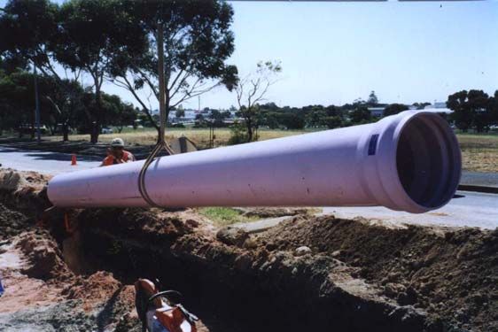
Important Disclaimer

The information, opinions, advice and recommendations contained in this publication are
offered only with the object of providing a better understanding of technical matters
associated with pipeline design etc, with Iplex Pipelines assuring no duty of care in respect
of them. This publication should not be used as the sole source of information. As it does
not refer to all relevant sources of information, reference should also be made to established
text books, and other published material. Readers should not act or rely upon any
information contained in this publication without taking appropriate professional advice which
relates to their particular circumstances. Pipes and fittings are shown as typical
configurations, however, in some cases, product dimensions may vary or be changed
without notice. If a dimension is critical please contact Iplex Pipelines Technical Marketing
Group for clarification.

Iplex Pipelines Australia                     2                                  3/11/2004
CONTENTS
                1.0 Introduction
                       1.1 Advantages
                       1.2 Applications
                2.0 Materials Properties
                       2.1 Physical Properties
                       2.2 Chemical Properties
                3.0 Product Specifications
                       3.1 Pipes
                       3.2 Rubber ring (dual hardness) joints
                       3.3 Rieber (fixed) ring joints
                       3.4 Solvent cements and priming fluids
                       3.5 Ductile iron fittings
                       3.6 PVC-U fittings
                       3.7 GRP fittings
                4.0 Product Codes
                       4.1 Pipes
                       4.2 Rubber rings
                       4.3 Jointing fluids
                       4.4 Solvent welding chemicals
                5.0 Product Range -Dimensions
                       5.1 Series 1 Rhino & White Rhino
                       5.2 Series 2 Blue Rhino
                       5.3 Fittings
                6.0 Hydraulic Design
                       6.1 Flow capacity determination
                       6.2 Pressure class selection
                       6.3 Water hammer, surges and cyclical effects
                7.0 Structural Design
                       7.1 Allowable cover heights
                       7.2 Thrust block design
                       7.3 Above ground suspended pipelines
                8.0 Installation
                       8.1 Handling and storage
                       8.2 Trench and embankment installation
                       8.3 Embedment
                       8.4 Jointing – using the solvent weld method
                       8.5 Jointing – using rubber ring seals
                       8.6 Expansion and contraction effects
                       8.7 Installing on curved alignments
                       8.8 Concrete encasement
                       8.9 Backfilling
                9.0 Field testing
                10.0 Case studies

                              -----ooo-----

Iplex Pipelines Australia                     3                        3/11/2004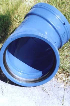
BLUE RHINO, WHITE RHINO & RHINO (Irrigation) PVC-M
                           PRESSURE PIPE
  1.0 INTRODUCTION

  Iplex modified PVC (PVC-M) pressure pipes are tough, high performance thermoplastic
  pipes which incorporate advanced technology and have superior physical characteristics
  over conventional unplasticized PVC (PVC-U) pipes. These include higher impact
  resistance, greater ductility, reduced weight and an increase in hydraulic capacity.

  Pipe outside diameters and pressure classes are in accordance with Australia/New Zealand
  Standard AS/NZS 4765 “Modified PVC (PVC-M) pipes for pressure applications” . These
  dimensions for Series 1 and 2 PVC-M are identical with Series 1 and 2 of AS/NZS 1477
  “PVC pipes and fittings for pressure applications”.

  Iplex Rhino pipes have been used extensively for irrigation since 1997. More recently, Blue
  Rhino and White Rhino pipes which are calcium / zinc stabilized, have been given a
  favourable assessment by the Water Services Association of Australia (WSAA) in Product
  Appraisal No.98/17. This document rates these Iplex pipes as Type “A” – that is for a life
  expectancy in excess of 100 years before major rehabilitation, when used in water and
  waste water pressure systems. It recommends these pipes for use in potable water supplies
  by municipal authorities.

  1.1 Advantages

  The increase in toughness and ductility of modified PVC-M permits the use of a higher
  design stress to produce a PVC pipe with reduced wall thickness but with improved overall
  performance. The larger bore will reduce pumping costs or for the same head there will be
  greater flow carrying capacity than would be the case for the equivalent PVC-U pipe.

                   Features                                                     Benefits

Increased internal diameter/hydraulic flow          Lower operating costs

Toughness and ductility                             Resistance to accidental handling/installation
                                                    damage
Excellent internal/external corrosion resistance    Long service life

Dimensions compatible with existing AS/NZS          Interchangeable with PVC-U      (and in the case of
1477-Series 1 and Series 2 systems                  Series 2 , ductile iron, HOBAS GRP and AC).

“Rieber” fixed ring jointing system                 Recently introduced system which eliminates
                                                    potential installation errors.

Special purpose deflection socket joint (Series 2   Up to 30 angular deflection off line after joining –
only) with dual hardness rubber ring                achievable with acceptable jointing effort

Light weight and larger bore.                       Ease of handling - approximately 30%
                                                    lighter than PVC-U together with significantly less
                                                    flow resistance

  1.2 Applications

  Iplex’s modified PVC pressure pipes are suitable for:-
  . major potable water supply trunk and reticulation mains

  Iplex Pipelines Australia                          4                                        3/11/2004
. industrial process pipelines
. effluent pipelines for pumped sewage, industrial and rural wastes
. slurry pipelines carrying abrasive and corrosive mine or quarry materials
. irrigation and turf watering systems
2.0 MATERIAL PROPERTIES
2.1 Physical properties:
The general physical properties of PVC-M are given in Table 2.1
Table 2.1 Physical properties
Property Value
Physical & mechanical
Specific gravity 1.42
Vicat softening temperaure – ISO 2507-2 ≥ 800C
Effect on potable water - AS 4020 Complies
Hydrostatic design stress - 17.5 MPa
Short term min. hoop stress at 1 hour and 200C 38.0 MPa
Minimum required strength (MRS) at 200C 24.5 MPa
extrapolated to 50 years
Minimum notched hoop strength at 200C 24.5 MPa
extrapolated to 50 years
Flexural modulus – ISO 9969 3000 MPa
Poisson’s Ratio 0.38 - 40
Thermal
Coefficient of linear thermal expansion 70 x 10-6 per degree C
Thermal conductivity 0.138 x 10⁻³ W/m.K
Specific heat 1045 J/kg.K
Maximum working temperature 60 oC
Fire resistance
Flammability Will not support
combustion
Ignitability – AS 1530 8
Smoke development – AS 1530 7
Spread of flame – AS 1530 0
Heat evolved – AS 1530 0
Electrical
Volume resistivity 1016 ohm.cm (60% RH)
Surface resistivity 1013 – 1014 ohm
Power factor 0.015 – 0.020 at 200C
Dielectric constant 3.4 – 3.6 at 250C (60 Hz)
Iplex Pipelines Australia 5 3/11/20042.1.1 Temperature effect on pressure rating:
Modified PVC pipes are suitable for service temperatures between 0°C and 50°C. For
temperatures above 20°C provision must be made for pressure de-rating in accordance with
Table 2.2 and are the same as for PVC-U.
Table 2.2 Thermal derating factors
Maximum Multiplication Factor
Service Temperature (°C) For Pressure Derating
20 1.00
30 0.90
40 0.70
50 0.50
2.2 Chemical resistance
Refer to the chemical resistance reference at www.iplex.com.au or the table for PVC-U
in AS 2032
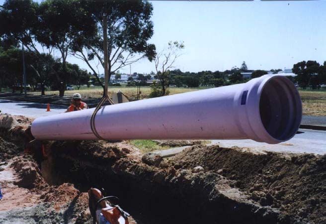
Iplex DN 450 PN12 Series 2 PVC-M pipes for recycled
water at Willunga, SA
Iplex Pipelines Australia 6 3/11/20043.0 PRODUCT SPECIFICATIONS
Iplex PVC-M pipes and associated materials are manufactured to relevant Australian
Standards under third party accredited quality assurance programs complying with AS/NZS
ISO 9002
3.1 Pipes:
Manufactured to Australian Standard AS/NZS 4765 “Modified PVC (PVC-M) pipes for
pressure applications”.
Iplex White Rhino (Series 1) and Blue Rhino (Series 2) PVC-M pipes
meet the requirements of WSAA Appraisal 98/17 for municipal water supplies .
Pipe Ends / Jointing:-
For Series 1 - spigot and socket for either solvent weld or rubber ring joints with either
fixed or separate seals.
For Series 2 - spigot and socket pipe with rubber ring joints with either fixed or separate
seals.
Pipe colour coding.
To readily distinguish between the types of Iplex Rhino modified PVC the pipes are normally
colour coded as given below. Other colours such as lilac/purple for recycled water, light grey
for sewage, and green for raw water may be specified at the time of ordering:-
Rhino ( Series 1) - pale green (originally) , e.g. for irrigation
White Rhino ( Series 1) - white – as per WSAA Appraisal 98/17
Blue Rhino (Series 2) - light blue – as per WSAA Appraisal 98/17
3.2 Dual hardness rubber ring joints:
Iplex dual hardness rubber rings which are supplied packed separately from the pipes
comply with AS 1646 “Ëlastomeric seals for waterworks purposes”
Series 1 pressure pipe rings are embossed with the letters “PR” and the nominal diameter of
pipe, e.g. “PR100” for jointing 100mm diameter pipe.
Series 2 carry the letter “PD” and are partially blue in colour.
Unless otherwise requested SBR rings are normally supplied. However, rings are
available in other polymers and which can be identified by a colour spot on the rear outer
circumference as follows:
Polymer Abbreviation Colour marking
Styrene-butadine rubber SBR Blue
Natural rubber NR Plain or white
Nitrile-butadine NBR Violet
Ethylene propylene-diene EPDM Green
3.3 Rieber rubber ring joints:
Iplex Rieber sealing rings which are fitted into the pipe socket at manufacture comply with
AS 1646 “Ëlastomeric seals for waterworks purposes”. They are manufactured from SBR
polymer. Colour coding is not visible.
Iplex Pipelines Australia 7 3/11/20043.4 Solvent weld joints, cements and priming fluids:
Iplex solvent welding chemicals are manufactured to AS 3879 (Int) .”Solvent cements and
priming fluids for use with PVC-M pipes and fittings”. These materials can be used for both
PVC-U and PVC-M pressure pipes and fittings. All Iplex premium solvent cements and
priming fluids are benzene free.
Iplex solvent cement – Type P is formulated for use in potable water pressure pipelines. It
develops high shear strengths when use in spigot and socket joints with interference fit.and
is green in colour for identification purposes. A clear version is also available.
Note that Type N is formulated for non pressure applications and has a gap filling capability.
It is generally coloured blue for identification purposes and must not be used for pressure
applications.
Iplex priming fluid must always be used when making solvent weld joints. It is generally
coloured pink for identification although clear is also available.
3.5 Ductile iron fittings
Conventional socketed fittings complying with AS 2544 – “Grey Iron Pressure Pipes and
Fittings” and AS 2280 – “Ductile Iron Pressure Pipes and Fittings” are generally suitable for
use with Blue Rhino as these pipes are Series 2, that is cast iron compatible. A complete
range of bends,tees reducers and flange-spigot pieces are available with Griptite rubber ring
sockets in sizes DN 100 to DN 450. A similar range of special cast iron fittings are also
available with Nortite rubber ring sockets for Series 1 Rhino and White Rhino in sizes DN
100 to DN 375. Other joint designs may also be acceptable. Iplex Pipelines should be
contacted to confirm the suitability of any particular range of fittings.
Example of a fusion bonded epoxy coated
ductile iron fitting
These fittings may be protected from corrosion using various alternatives.(i) fusion bonded
polymer (preferred) (ii) cement lining and polyethylene wrap.(. (iii) epoxy coating
Iplex Pipelines Australia 8 3/11/20043.6 PVC-U fittings The Iplex solvent weld PVC-U pressure fitting range is compatible with Series 1 Rhino and is available for pipes DN 100 and DN150. In the case of Series 2 Blue Rhino, the Iplex Blue Brute PVC-U fittings have been manufactured for many years but in the DN100 size only. Owing to the limited range it is likely these will become not stock items in the near future. The fittings are suitable for all classes of pipe up to PN16 and comply with the requirements of AS/NZS 1477 “PVC_U Pressure Pipes and Fittings”. Being socketed fittings they have the same deflection joints and dual hardness rubber rings as Blue Rhino pipes. All PVC fittings are electrically non conductive and do not require corrosion protection in aggressive environments. 3.7 GRP fittings Where non-metallic fittings are required for Blue Rhino pipes for sizes of DN150 Series 2 or greater, a complete range of Iplex GRP fittings complying with AS 2634 “Chemical Plant Equipment made from Glass-Fibre Reinforced Plastics (GRP) based on Thermosetting Resins” is available. Pressure ratings are the same as for Blue Rhino pipes.. Where socketed they will be supplied with dual hardness Blue Rhino rubber rings which are identical with the Series 2 pipe rubber rings. However these sockets are not be designed for deflection. All GRP fittings are electrically non conductive and do not require corrosion protection in aggressive environments. Iplex Pipelines Australia 9 3/11/2004
4.0 PRODUCT CODES

4.1 Pipes:

    The product computer identification codes used by Iplex Pipelines are given in the
    following table and are of the form “ÄAAA(A)BBCCC(D)” - the brackets indicate the
    symbol is used only where required

              Product description                 Pressure      Nominal      Pipe effective
                                                    class       diameter         length
                                   Code          PN     Code   DN    Code   metres    Code
                                 ”AAAA(A                “BB”        “CCC”             “(D)”
                                    )”
            Pipes for dual
       hardness rings –for
       ring Code see Cl 4.2
           Rhino Series 1         PPRR           6      06     100    100      1           A
         Lilac/purple Rhino       PPRRL          9      09     150    150      2           B
               Series 1
       Blue Rhino Series 2         PDRR          12     12     200    200      3           C
       Lilac Rhino Series 2       PDRRL          15     15     225    225      4           D
         Grey/cream Rhino         PDRRC          16     16     250    250      5           E
               Series 2
                                                 18     18     300    300      6               -
                                                 20     20     375    375
                                                               450*   450
        Pipes with Rieber
          fixed ring –ring
      included in pipe Code
          Rhino Series 1          PPHR           6      06     100    100      1           A
        Lilac/purple Rhino        PPHRL          9      09     150    150      2           B
              Series 1
       Blue Rhino Series 2         PDHR          12     12     200    200      3           C
       Lilac Rhino Series 2       PDHRL          15     15     225    225      4           D
        Grey/cream Rhino          PDHRC          16     16     250    250      5           E
              Series 2
                                                 18     18     300    300      6               -
                                                 20     20     375    375
                                                               450*   450

                            * and larger sizes
Examples:

    (i) The code for a DN 200 Blue Rhino (Series 2) Class 12 water pressure pipe with
deflection joint and in 3 m lengths is:
                                        “PDRR12200C”

    (ii)The code for a DN 150 Lilac Rhino ( Series 2 ) Class 16 recycled water pressure pipe
    with the Rieber fixed ring joint in 6 m lengths is :
                                        “PDHRL16150”

Iplex Pipelines Australia                         10                               3/11/2004
Figure 4.1a : Dual hardness rubber ring joint
(Series 1 pipe only –ring packed separately for
installation on site)
Figure 4.1b : Dual hardness rubber ring
deflection joint (Series 2 pipe only- ring packed
separately for installation on site)
Figure 4.2: Rieber rubber ring joint (Series 1 and 2 pipe -
ring supplied pre installed in pipe socket and cannot be
removed )
4.2 Dual hardenss rubber rings:
Product Codes for the separate Iplex dual hardness elastomeric (SBR) rings are as follow:
Diameter Series 1 Series 2
DN Code Code
100 PRRZ100SBR PRRB100SBR
150 PRRZ150SBR PRRB150SBR
200 PRRZ200SBR PRRB200SBR
225 PRRZ225SBR PRRB225SBR
250 PRRZ250SBR PRRB250SBR
300 PRRZ300SBR PRRB300SBR
375 PRRZ375SBR PRRB37SBRR
450 PRRB450SBR
Note: Natural rubber rings are no longer supplied. ( Codes for natural rubber did not include the letters
“SBR”)
Iplex Pipelines Australia 11 3/11/20044.3 Jointing fluids :
Product Codes for Iplex jointing fluids for rubber ring joints are as follows:
Container Code Code
Size (grams) Iplex Iplex Plus*
Standard (Bactericidal)
500 JLO10500 JLB10500
1000 JLO11000 JLB11000
4000 JLO14000 JLB14000
*The product is accredited under the Watermark Scheme MP 52
Specification 014 Licence No. W 103 and type tested to AS 4020.
4.4 Solvent welding chemicals:
Product Codes for Iplex solvent welding chemicals for pressure pipes
Solvent Cement - Type P
Container Code Colour
Size (ml)
125 JPG0125 Green
250 JPG0250 Green
500 JPG0500 Green
4000 JPG04000 Green
500 JPC0500 Clear
Priming Fluid
Container Code Colour
Size (ml)
250 JR0250 red
500 JR0500 red
1000 JR1000 red
4000 JR4000 red
250 JC0250 clear
500 JC0500 clear
Iplex Pipelines Australia 12 3/11/20045.0 PRODUCT RANGE – DIMENSIONS
5.1– SERIES 1 PVC-M
Table 5.1 Rhino & White Rhino Dimensions
Nominal Mean
Diameter Outside PN6 PN9 PN12 PN15 PN18
DN Diameter
T ID T ID T ID T ID T ID
100 114.3 3.2 108.7 3.2 108.0 4.1 106.1 5.1 104.2 6.0 102.3
150 160.3 3.7 152.9 4.3 151.7 5.7 148.9 7.1 146.2 8.3 143.7
200 225.3 5.2 215.0 6.1 213.1 8.0 209.3 9.9 205.5 11.7 202.0
225 250.4 5.8 238.8 6.7 237.0 8.8 232.8 10.9 228.6 13.1 224.3
250 280.4 6.4 267.6 7.5 265.5 9.9 260.6 12.4 255.6 14.5 251.4
300 315.5 7.2 301.1 8.4 298.7 11.2 293.2 13.8 288.0 16.3 282.9
375 400.5 9.2 382.1 10.6 379.3 14.1 372.3 17.5 365.6 20.7 359.1
All dimensions are in millimetres T = mean wall thickness ID = mean inside diameter
5.2 SERIES 2 PVC-M
Table 5.2 Blue Rhino Dimensions
Nominal Mean PN9 PN12 PN16 PN20
Diameter Outside T ID T ID T ID T ID
DN Diameter
100 121.9 - - 4.4 113.1 5.7 110.3 7.1 107.8
150 177.4 - - 6.3 164.8 8.3 160.8 10.2 157.0
200 232.3 - - 8.2 215.9 10.8 210.7 13.3 205.8
225 259.3 7.0 245.4 9.2 241.0 12.0 235.1 14.8 229.7
250 286.2 7.7 270.9 10.1 266.0 13.3 259.7 16.4 253.4
300 345.4 9.3 326.9 12.2 321.0 16.0 313.5 19.7 306.1
375 426.2 11.4 403.5 14.9 396.4 19.7 386.9 24.3 377.7
450 507.0 13.5 480.1 17.8 471.5 23.4 460.2 - -
All dimensions are in millimetres T = mean wall thickness ID = mean inside diameter
Effective Lengths. The standard length of all pipes is 6 m + 50, -0 mm, except for
diameters DN 100 to DN 225 S2 with deflection joints which have
lengths of 4 m + 50, - 0 mm .
5.3 FITTINGS
Bends, tees, reducers, valve connectors are available for the full size range of Iplex Series 1
and Series 2 modified PVC pipes with appropriate socketed joints. Refer to Section 3 for
relevant specifications which will in turn give dimensions.
Where a flange connection is required a flange-socket cast iron or flange-spigot non-
metallic ( i.e.PVC or GRP) adaptors should be used.
Iplex Pipelines Australia 13 3/11/20046 .0 HYDRAULIC DESIGN
6.1 Flow capacity determination
The capacity of a pipeline can vary due to various factors, which include:
. growth of slime which will vary with age of the pipeline and available nutrient in the water
. roughening, due to the wear by abrasive solids
. siltation or settlement of suspended particulate matter
. joint imperfections/fitting types and configurations
To assist the designer in selecting the appropriate diameter pipe flow calculation software is
available from Iplex. Alternatively flow resistance charts specifically for either Series 1 or 2
PVC-M are published in the Iplex brochures for Rhino and Blue Rhino. These tools will
enable the designer to determine the relationship between friction loss , discharge and
velocity for all available diameters and classes of the Iplex PVC-M range.
Calculations using either approach are based on the Colebrook White Transition Equation
and it is assumed pipes are flowing full. This equation takes into account, liquid viscosity and
pipe roughness, and is recognised as being one of the most accurate in general use but
requires an iterative solution. By using the Iplex software It is possible to vary the
temperature and pipe roughness to suit site conditions. Iplex flow resistance charts are by
necessity limited to the following fixed parameters.i.e.
Nominated temperature of 20°C which corresponds to a kinematic viscosity of water
υ = 1.01 x 10⁻⁶ m2/s
Wall equivalent roughness, k = 0.003 x 10⁻³ m
This value of the equivalent roughness coefficient “k” assumes the PVC-M pipeline is
straight, clean and concentrically jointed without fittings. Possible values ranging between
0.003 to 0.015 mm are given in AS 2200 “Design Charts for Water Supply and Sewerage”
for PVC. An approximate allowance for the effect of variation in water temperature can be
made by increasing the chart value of the head loss by 1% for each 3ºC below 20º and by
decreasing it by 1% for each 3ºC in excess of 20º. of pressure rating
6.2 Pressure class selection
The nominal pressure rating in kilopascals of a PVC-M pressure pipe is equal to PN
multiplied by 100. This rated pressure should not be exceeded at any location in the pipeline
by the maximum operating pressure including water hammer pressure surcharges. Where
the pipeline will be operating at elevated temperatures, that is higher than 20 0C nominal
rating should be multiplied by the re-rating factor for that temperature obtained from Table
6.1.
Table 6.1 Re-rating factors for elevated temperatures
Temperature 0C Re-rating factor
20 1.0
25 0.95
30 0.9
35 0.8
40 0.7
45 0.6
50 0.5
Iplex Pipelines Australia 14 3/11/2004Fatigue and structural considerations discussed in Sections 6.3 and 7.1 may also affect the
choice of a suitable class. For example the maximum design head should include the worst
case water hammer head. Typically this may occur due to pump stoppage caused by a
power failure.
Note that Class PN9 is the minimum which should be used for full vacuum conditions in a
buried pipeline assuming these pipes have been embedded in a properly compacted non-
cohesive material (such as sand or gravel) surrounding the pipe fully. Above ground
pipelines subject to full vacuum should be a minimum of Class PN12.
MAX. POSITIVE SURGE
MAX. POSITIVE SURGE
(ON STOPPING)
(ON STARTING)
HYDRAULIC
GRADIENT
DESIGN HEAD
(OPERATING
)
NO FLOW STATIC HEAD
MIN NEGATIVE SURGE
DISCHA
(ON STOPPING)
SUB ATMOSPHERIC PRESSURE
PUMP
Figure 6.1 Typical hydraulic grades and surge envelopes required for design
Combined air release and anti-vacuum valves must be installed at local high points in each
section of a pipeline, with a maximum spacing not exceeding 0.5 kilometres, so as to
maintain full flow and limit the occurrence of vacuum conditions.
6.3 Water hammer surges and cyclical effects
Water hammer effects in thermoplastic materials are considerably reduced in thermoplastic
materials including modified PVC when compared with iron steel and concrete due to the
much lower modulus of elasticity. Typical values for celerities for PVC-M pipes of different
wall classes and therefore thicknesses are given in the following table.
Table 6.1 Water hammer celerities
Nominal pressure Celerity
PN (m/s)
6 254
9 276
12 319
15 357
16 365
18 392
20 409
PVC-M has characteristics with respect to fatigue under cyclical pressures which are similar
to PVC-U. The designer should into account the frequency of pressure fluctuations during
the life of the pipeline. That is the amplitude of the pressure change between the maximum
and minimum steady state operating pressures plus water hammer effects, when divided by
Iplex Pipelines Australia 15 3/11/2004the load factor given in Table 6.2 should not exceed the nominal class pressure rating of the
pipeline.
In practice the pressure changes in water reticulation systems are seldom of sufficient
amplitude and frequency for fatigue to affect pipe class selection, but they can be an
important consideration for sewer rising mains. The amplitude will be the difference in the
hydraulic gradients for when the pump is running and when stopped
Table 6.2 PVC-M fatigue load factors
Frequency of Frequency per Fatigue load
pressure variation day for 50 years factor
26,400 1.4 1.00
100,000 5.5 0.67
250,000 14 0.51
500,000 27 0.41
750,000 41 0.36
1,000,000 55 0.33
2,000,000 110 0.33
5,000,000 274 0.33
The frequency is defined as the number of combined pump start and stop cycles. If an
allowance is considered necessary to allow for attenuation of water hammer oscillations the
frequency can then be taken as being twice the number of start/ stop cycles. (It can be
shown mathematically that this is appropriate for the exponential decay typical of pressure
surge oscillations).
PUMP RUNNING
OPERATING PRESSURE
(FOR FATIGUE DESIGN)
PRESSURE AMPLITUDE
single cycle single cycle
PUMP STOPPED
TIME
Figure 6.2 Inputs for fatigue design – pressure amplitude and frequency
Examples:
1) Question A water main will for most of its lifetime experience diurnal operating pressures
of 55 metres and 85 metres , that is a pressure change amplitude of 30 metres with a total
number of cycles over (say) 50 years of 18250 fluctuations.
Solution Since the maximum operating pressure is 85 metre and from Table 6.2 the
fatigue load factor is 1, a PN 9 pipe would be suitable.
2) Question A sewer pump station has a wet well capacity which will require a pump start
(and stop) 3 times per hour on average over a 40 year design life (for the rising main). The
static head on the main without pump operation is 12 metres and with a maximum pump
station operating of 29 metre. A surge analysis shows the normal shut down phase
Iplex Pipelines Australia 16 3/11/2004generates a (maximum) hammer effect of 32 metre maximum head and (minimum) minus 8
metre head at shut down.
Solution: Steady state operating conditions would suggest that a Class 6 pipe might be
selected. However the amplitude of the maximum pressure transient during the pumping
cycle is 32-(-8)=40 metres and this must be checked for fatigue effect. The number of
cycles used for this check is usually the number of pump stop/start operations. But in this
case this number of cycles is to be multiplied by 2, i.e.1051,200 x 2 = 2,102,400 to allow for
surge wave attenuation .
The dynamic fatigue consideration requires a pipe to be selected with a pressure rating
which when multiplied by the fatigue factor will give a value greater than the pressure
fluctuation amplitude of 40 metres. Therefore the class rating can be obtained by dividing the
pressure amplitude by the fatigue factor obtained from Table 6.2 for a frequency of 2.1
million pressure fluctuations. ( It should be noted that a pressure amplitude of 0.33 times the
rated pressure is the threshold value below which fatigue cannot occur irrespective of
frequency.)
Here 40 / 0.33 = 120 m. Therefore the appropriate pipe class selection would be PN 12
rated to 122 metres. (Alternatively the design graph in Figure 6.3 could be used to directly
determine the appropriate class)
Figure 6.3
Design Graphs - Dynamic Operating Pressures
for PVC-M Classes
1000
Pressure change amplitude
Class 20
100 Class 18
Class 16
(metres)
Class 15
Class 12
10 Class 9
Class 6
1
1 10 100 1000 10000 100000 1000000 10000000
Pressure change frequency over operating life
Iplex Pipelines Australia 17 3/11/20047 STRUCTURAL DESIGN
7.1 Allowable cover heights : In engineering terminology the Iplex range of RHINO pipes
are considered to be “flexible” pipes, which means they are designed to deform or deflect
diametrically within specified limits without structural damage.
The external soil and live loadings above flexible pipes may cause a decrease in the
vertical diameter and an increase in the horizontal diameter of the pipe. The horizontal
movement of the pipe walls in the soil material at the sides develops a passive
resistance within the soil to support the external load. That is, the pipeline performance
is influenced by the soil type, density and height of water table. The higher the effective
soil modules at pipe depth, the less the pipe will deflect.
Initial deflections of up to 3% are permissible and will not affect the pressure rating of the
pipe. A complete design procedure is available for Iplex PVC-M pipes. Consult Iplex for
further details or refer to AS/NZS 2566.1 “Buried flexible pipelines” Part 1 Structural
design”. Iplex has developed computer software which can be purchased by engineers.
It is based on this Standard and covers all its pipeline materials in addition to Series 1 &
2 PVC-M.
Table 7.1 Stiffnesses for PVC-M pressure pipes
Nominal Estimated stiffness
pressure PN (N/m.m)
6 2,500
9 4,200
12 10,200
15 20,500
16 23,400
18 36,400
20 46,600
7.1.1 Minimum Cover Height –
For areas with no traffic loading a minimum cover height of 450mm to the top of the pipe
should be adopted. Under sealed roadways the minimum cover height is 600mm or 750mm
in unsealed roadways, and pipe embedment material should have a minimum compaction
Density Index of 65%. After pipes are laid and centred in the trench, the embedment
material should be compacted in 80-100mm layers to the specified density. The embedment
should continue above the pipe to provide protection from the back fill. That is a height
above the pipe of 80-150mm may be required.
7.2 Thrust block design for fittings
Where the pipeline system is rubber ring jointed there will be unbalanced forces at changes
of size or direction of the pipeline, that is at bends, tees, reducers, valves and closed ends.
In buried installations, fittings are usually restrained by blocks of concrete cast in situ. These
thrust blocks are formed and sized to convert the applied force at the fitting to a pressure at
the soil / concrete interface which can be safely resisted by the soil. The resistance which
can be provided will depend on the soil type and depth. Where bends are in the vertical
plane , convex and close to the mass of a concrete anchor block alone may have to be used.
Iplex Pipelines Australia 18 3/11/2004Figure 7 Typical thrust block arrangements Iplex Pipelines Australia 19 3/11/2004
Table 7.2 Hydrostatic forces in kilonewtons on rubber ring jointed fittings per 10 metres
hydrostatic head

 Pipe DN         Pipe OD        Bend        Bend         Bend            Bend          Tee/
                                 90          45           22.5           11.25        Closed
                               degrees     degrees      degrees         degrees        end/
                                                                                       valve

    100            122              1.62     0.88         0.45           0.22          1.15
    150            177              3.41     1.85         0.94           0.47          2.41
    200            232              5.86     3.18         1.61           0.81          4.14
    225            259              7.31     3.96         2.01           1.01          5.17
    250            286              8.91     4.83         2.45           1.23          6.30
    300            345             12.96     7.02         3.57           1.79          9.16
    375            426             19.76    10.71         5.44           2.72         13.97
    450            507             27.99    15.17         7.71           3.86         19.79

Note: For concentric reducers the resultant thrust will be the difference between the “closed
end“forces for the two pipe sizes.

Table 7.3 Soil bearing capacities in kPa – apply mimimum factor of safety of 1.1

Soil group           Minimum soil cover above centre line of thrust block in metres
description as
per AS 1786
                            0.75             1.0                 1.25             1.5

    GW,SW                   57                76                  95              114
    GP,SP                   48                64                  80               97
    GM,SM                   48                64                  80               96
    GC,SC                   79                92                 105              119
     CL                     74                85                  95              106
     ML                     69                81                  93              106
     OH                      0                 0                   0                0

Thrust blocks must be formed in shape to distribute the hydrostatic force to a plane surface
of undisturbed soil which is approximately perpendicular to the imposed load. The equation
for this calculation is :

A = T/ b x f
Where A = area perpendicular to force (m2)
T = hydrostatic thrust (kN)
   b = soil bearing capacity (kPa)
   f = factor of safety

Example:
 Question A DN300 Blue Rhino pipeline has a maximum operating head (include field test
heads) of 150 metres. What is the minimum area for a thrust block for a 90 degree ductile
iron bend buried with 1 metre cover to centreline in a type SC soil
Solution: From Table hydrostatic thrust “T” is 12.96 kN x 15 = 194.4 kN. From Table b = 92
kPa. Therefore:
A = 194.4 / (92 x 1.3) = 1.62 m2

Iplex Pipelines Australia                       20                                    3/11/2004
7.3 Above ground suspended pipelines
Modified PVC pressure pipes can be used above ground where protection from long term
exposure to ultra violet radiation is provided. In direct sunlight acrylic paint is a suitable
barrier. As a general rule pipes should be rubber ring jointed and a minimum class of PN 12.
Full circle supports should surround the pipes ” padded” with compressible material such as
3mm thick insertion rubber to protect the exterior surface of the pipe from abrasion. Special
provision for thrust support of fittings is required. The following table indicates the maximum
support spacing for pipes filled with water where aesthetic considerations require long term
deflections to be limited to the span distance divided by 600.
Table 7.4 Span between supports (for deflections less than L/600)
Pipe designation Span ( metre)
DN 100 12 or higher 2
DN 150 PN 12 or higher 2
DN 200 to DN 450 PN 12 or higher 3
DN 450 PN 9 White Rhino for irrigation
supply in Hunter Valley , NSW
Iplex Pipelines Australia 21 3/11/20048.0 INSTALLATION
8.1..Handling and storage:
While PVC-M pipes are light and easy to handle, careless handling can cause unnecessary
damage. Pipes and fittings should not be dropped or thrown onto hard surfaces or allowed
to come into contact with sharp objects which could inflict deep scratches. PVC-M pipes
should not be allowed to slide across sharp edges. During construction storage areas
should be selected which are free from surface irregularities such as stones, branches or
other sharp projections.
PVC-M pipes are subject to distortion under high loads, particularly at elevated
temperatures, and also to bowing due to uneven heating; stacks. They should therefore be
protected from direct sunlight, or other heat source, if stored for extended periods.
Socketed pipes should be stacked in layers with sockets placed at alternative ends of the
rack, and protruding, to avoid uneven stacks and distortion. The sockets should not be
allowed to carry loads.
If mechanical handling equipment such as forklifts or cranes are to be used on bundles,
adequate spreader and lifting bars should be provided. Wire slings must be kept clear of the
pipes. When unloading alongside excavated trenches, it is recommended that pipes be
placed on the opposite side of the trench from excavated material.
Rubber rings, jointing fluid, solvent cement and priming fluid should be stored under cover
until pipe laying commences.
8.2 Trench excavation
Trenches should be excavated in accordance with plans and specifications. They should
may be as narrow as practicable at the level of the top of the pipe and, in a straight trench,
have a bed width at least as given in the following table to provide space for compaction of
the embedment material in the side support zone.
Table 8.1 Embedment dimensions
DN h B k
100 75 300 100
150 75 350 100
200 100 500 150
225 100 530 150
250 100 550 150
300 100 600 150
375 100 780 150
450 100 850 150
Figure 1 Embedment, clearance and cover dimensions
Iplex Pipelines Australia 22 3/11/20048.3 Embedment The quality of the embedment material, its compaction, together with the nature of the undisturbed material of the trench wall, are all relevant to the ultimate performance of modified PVC pipes once installed. The trench bottom should be as smooth as possible and to grade. Embedment material which includes bedding, side support and overlay material should as a general rule be non-cohesive granular material. Pipes should not be buried in contact with soil particle sizes larger than 5% of diameter, with 20 mm as maximum. Soil clods must be excluded from the pipe embedment zone and under no circumstances should temporary supports such as bricks or timber be left under or in contact with pipes. If the excavated material is not granular or friable, or does not comply with the project specification, then suitable embedment must be imported. Jointing or “clearance holes” should be excavated in the bedding for pipe sockets to ensure the pipes are evenly supported along the full length. In the absence of any specification and if the pipe Classes are PN 6 or PN9, it is important that only non-cohesive or granular embedment be used. Careful attention to the placement of embedment material to the specified relative compaction with an absence of voids is important. 8.4 Jointing - using the solvent weld method To achieve strong leak free joints in a pressure pipe the correct Type P solvent cement must be used . Note that the joint for pressure pipes is designed as an interference fit and only after the application of the solvent will it be possible to close the joint fully . 8.4.1 How solvent cement works: Iplex solvent is a solution of resin in a mixture of solvents which soften the surfaces when applied to PVC-M pipes and PVC-U fittings. It is not a glue as adhesion is due to the solidification of dissolved PVC polymer. A thin uniform coat is applied to both the spigot and socket and the joint is assembled while the surfaces are still wet and fluid. The cement layers intermingle and become one. The strength of the joint develops as the solvent permeates the PVC and the volatile constituents evaporate. 8.4.2 Importance of priming fluids: Before applying the solvent cement, it is essential to use Iplex Priming Fluid for successful jointing as the fluid not only cleans and degreases, but removes the glazed surface from PVC which allows the solvent cement to permeate into the wall of the pipe or fitting. Iplex Pipelines Australia 23 3/11/2004
Table 8.1 Estimated usage rates of solvent weld chemicals
                       (number of joints per 500 ml container)
                 Nominal diameter    Priming fluid      Solvent
                        DN                              cement
                        100               70              25
                        150               45              15
                        200               25              10
                        225               15               7
                        250               12               6
                        300                9               5
                        375                4               3
                        450              n.a.             n.a.

There are two types of solvent cement joints pressure joints which require interference fit
and non - pressure joints which may have a small clearance when assembled.
Iplex solvent cements are formulated specifically for each of these applications. Each
product is clearly colour coded in accordance with AS 3879(Int.) for easy identification;
green for pressure, blue for non-pressure and red for priming.
Iplex Solvent Cement - Type P
Type P is used for pressurized potable water installations and is formulated to develop high
shear strengths with interference fit.
Iplex Solvent Cement - Type N
Type N is used for non-pressure applications and is formulated with the gap filling properties
needed with a clearance fit. IT MUST NOT BE USED FOR PRESSURE APPLICATIONS.
Iplex Priming Fluid
Priming fluid is used to remove grease and dirt and then to etch the glossy surface of PVC
pipes and fittings. It must be applied with a clean, lint free cotton cloth.
Brushing the priming fluid on or simply pouring the fluid over the pipes and fittings will not
remove grease and dirt.

8.4.3 Solvent weld jointing instructions

Follow steps 1 - 9 carefully. Short cuts will result in poor joints that are likely to cause
system failure.
Do not work with hot pipes or on hot windy days without protecting pipes.
Keep lid on to minimise evaporation.
Use solvent cements within twelve months of the date stamped on the bottom of the
bottle/can. If the solvent cement has become so thick that it does not flow easily, discard.

    1   Cut spigot square and deburr
        Cut the spigot as square as possible using a mitre box and hacksaw or power saw.
        Remove all swarf and burrs from both inside and outside edges with a knife, file,
        reamer or sandpaper. Swarf and burrs if left, will wipe off the solvent cement and
        prevent proper jointing. Also swarf inside pipes can become dislodged and jam taps
        and valves.
    2   Check alignment
        Check the pipe and spigot or fittings for proper alignment. The time for any
        adjustments is now, not later.
    3   Mark clearly
        Mark the spigot with a pencil or marker at a distance equal to the internal depth of
        the socket. Only use pencil or a marker. Do not score or damage the surface of the
        pipe or fitting.

Iplex Pipelines Australia                     24                                  3/11/2004
4 Dry fit the joint
For pressure pipes interference fit must be reached before the spigot is inserted fully
to the pencil mark.
5 Clean and soften the surface
Thoroughly clean the inside of the socket and the area between the pencil mark and
the spigot end with a clean, lint free cotton cloth dipped in priming fluid (do not use
synthetic material). This removes dirt and grease and softens the PVC surface. Do
no brush or pour the priming fluid on.
6 Coat socket first - then spigot
Apply a thin, uniform coat of Iplex solvent cement to the socket. Take care to ensure
that solvent build up does not occur in the root of the socket - pooling of cement there
will severely weaken the pipe or fitting. Then apply a uniform coat of solvent cement
to the external surface of the spigot up to the pencil mark.
7 Assemble-hold for 30 seconds
Assemble the joint quickly before the cement dries by pushing the spigot firmly into
the socket as far as the pencil mark, ending with a quarter turn to spread the cement
evenly. Hold the joint in this position for at least thirty seconds without movement.
8 A vital 5 minutes
Wipe off the excess solvent cement from the outside of the joint and where possible
from the inside of the joint. Do not disturb the joint for at least a further five minutes-
movement may break the initial bond.
9 Curing and testing
Cure time is the time taken for the solvent weld joint to reach the pressure rating of
the pipe
- Do not pressure test the joint for at least 24 hours.
Safety precautions for solvent weld procedures
Solvent cement and priming fluids are highly flammable.
In the event of fire, smother with sand or earth or use suitable fire extinguisher
Store solvent cements and priming fluid in a cool place away from heat, flames and sparks.
Ensure can lids are tightly closed when not in use.
Do not add any other ingredients or solvents to these products.
Do not use solvent cements or priming fluid in confined spaces without adequate ventilation,
or near open flames or sparks.
Do not smoke while using these products.
If spilt on skin, wash off with soap and water.
If poisoning occurs, consult a doctor or Poisons Information Centre.
Keep container sealed when not in use.
If swallowed:
Solvent Cement
If swallowed and more than 15 minutes from a hospital induce vomiting.
Preferably using Ipecac Syrup APF if available.
Priming Fluid
Do not induce vomiting.
Give a glass of water.
Iplex Pipelines Australia 25 3/11/20048.5.1 Dual hardness rubber ring joint field installation
Iplex PVC-M Rhino, White Rhino and Blue Rhino rubber ring jointed pipes are supplied with
the common ( Series 1 and Series 2 respectively) dual hardness rings which fit easily into
the integral socket of each length It is essential to ensure that Series 1 and Series 2 rings
are used with the corresponding Series of pipes.
SBR rings are standard. However rings are available made of other polymers. These can be
identified using the standard colour code. These colour patches will appear on the rear outer
circumference .
Table 8.2 Dual hardness ring – polymer types
Polymer Abbreviation Colour marking
Styrene-butadine rubber SBR Blue
Natural rubber NR Plain or white
Nitrile-butadine NBR Violet
Ethylene propylene-diene EPDM Green
8.5.1.1 Jointing procedure for dual hardness ring joint
1 Clean :Remove all dust and dirt from the pipe spigot and socket paying particular
attention to cleaning the ring groove.
2 Install ring : Install the rubber ring ensuring it seats evenly in the PVC-M socket with
the tip of the ’V’ form pointing outwards
3 Apply lubricant : Apply lubricant to the spigot, fully covering the circumference up to
the witness mark. Ensure the lubricant covers the pipe chamfer but do no lubricate
the rubber ring or ring groove.
4 Push spigot into socket: Using a crowbar and protective block of timber, apply force
to the socket of the introduced pipe push the joint home with the witness mark just
visible.
Note: Where a cut end is being joined ensure that both chamfer and witness mark have
been applied to match the manufactured dimensions.
8.5.2 Rieber fixed ring joint field installation
Pipes which may be supplied with the Rieber jointing system include the Iplex range of
modified PVC Rhino, White Rhino and Blue Rhino . The Rieber seal is fitted at the time of
manufacture and MUST NOT BE REMOVED subsequently. If the ring is tampered with or
damaged in any way after leaving the factory then the socket and affected ring must be cut
off and scrapped. It is essential to use Iplex Standard or Iplex Plus bactericidal jointing fluid
with the Rieber joint –see Clause 8.5.3
8.5.2.1 Jointing procedure for Rieber joint
1 Clean :Remove all dust and dirt from the pipe spigot and socket paying particular
attention to the cleanliness of the fixed ring
2 Lubricate : Apply lubricant to the spigot, fully covering the circumference up to the
witness mark. ). Ensure the lubricant is also applied to the pipe chamfer.
3 Cut pipes PVC-M pipes can be cut to length on site using a hand saw. Ensure that
the cut end is then chamfered with an appropriate field lathing tool to the correct
Iplex Pipelines Australia 26 3/11/2004length . Both chamfer and new witness mark should replicate the manufactured
dimensions.
4 Assembly: Using a crowbar and protective block of timber, apply force to the socket
of the introduced pipe push the joint home until the witness mark is just visible.
Note: The distance of the witness mark from the end differs for the two types of jointing
systems i.e. dual hardness and Rieber.
8.5.3 Jointing fluids (lubricants)
Note that it is essential to use Iplex Standard or Iplex Plus bactericidal jointing fluid with all
Iplex PVC-M elastomeric jointed systems. Other lubricants especially MINERAL BASED
GREASES MUST NOT BE USED .
For potable water supplies it is recommended that the Iplex Plus bactericidal jointing fluid be
because:-
During installation bacteria can enter the system and form a colony in the joint area which is
very resistant even to high levels of chlorine. This can cause continuing infection of the line.
Iplex Plus contains a bactericide which is designed to limit the growth of bacteria by
disinfection at its source.
Lowers jointing forces.- use of Iplex Plus can lower jointing forces considerably
Water soluble The fluid is quickly removed from potable water systems when flushing
commences.
Safe - Iplex Plus has no detrimental effect on the rubbers used in gasket materials. If
insufficient Iplex Plus is available to complete jointing pipes for non potable water
applications a solution of soap and water can be used until extra lubricant is delivered. This
cannot be done for water supply pipelines as they will usually require the use of approved
bactericidal lubricants.
Keep container closed when not in use to avoid spillage or contamination by dust or dirt.
Safety Precautions
Avoid contact with eyes. If contact occurs flush with copious water.
If ingested drink copious water.
8.6 Expansion and contraction
Distortion can occur when laying pipes in direct sunlight. When one side of the pipe is hotter
than the other it may develop a slightly bent shape which may make jointing difficult.
Plastic pipe will contract as it cools, after laying in hot weather. A 6 metre length of PVC-M
will expand or contract approximately 5mm for each 10ºC rise or fall in temperature. The
following precautions should be taken to ensure that the joints do not pull apart:
Solvent cement jointing process requires the pipes to unrestrained until a strong bond has
developed. Laying is best done in the cooler parts of the day.
Rubber ring systems will allow for thermal movement of the pipeline after laying.
In both cases backfill each length, at least partially, as laying proceeds.
Iplex Pipelines Australia 27 3/11/20048.7 Installing on curved alignments
PVC-M pipes are flexible enough to be easily curved. Pipes should always be joined directly
in line before alignment of the pipes is altered. Pipes should be curved evenly along their
length so that the strain on each joint is minimised. No pipe should be curved to a centreline
radius less than that given in Table 8.3.
Table 8. 3 Minimum pipeline radii
Pipe Class Radius of curved pipe*
12 130 times pipe diameter
16 180 times pipe diameter
20 250 times pipe diameter
*For Series 1 solvent weld, dual hardness RR & Rieber RR joints
and for Series 2 Rieber RR joints
However note that some authorities may not allow PVC-M pipes to be curved or may not
allow curved PVC-M pipes to be drilled or tapped.
Blue Rhino Series 2 pipe with dual hardness rubber rings can be deflected at each joint by
up to 3 degrees. However joints must always be made while the two pipes are fully aligned.
Changes in alignment to give “effective radii” as shown in Table 8.4 may then be made while
individual pipes remain straight. These effective radii are independent of the diameter of
pipe.
Table 8.4 Minimum effective pipeline radii for Iplex Series 2 deflection joints
Deflection 4 metre* effective length 6 metre effective length
(degrees)
Offset Radius (m) Offset Radius (m)
(mm) (mm)
1 69 230 105 344
2 139 115 209 172
3 209 77 314 115
* Effective length for DN 100 to DN 225 Blue Rhino with dual hardness rings. Special
“short” lengths may be manufactured in other diameters by arrangement
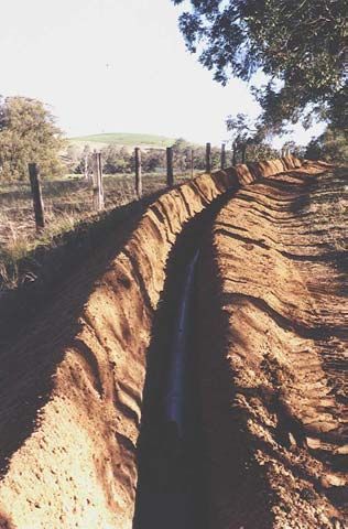
DN 150 PN 6 S1 Rhino
pipeline laid on a curved
alignment near Broke, NSW
Iplex Pipelines Australia 28 3/11/20048.8 Concrete Encasement
Iplex modified PVC pipes may be encased in concrete. Where the concrete face cannot be
located on a socket, compressible material approximately 3mm thick should be wrapped
around the circumference of the pipe to a distance of about 100mm inwards from the face.
By encircling the pipes at the entry and exit points, any potential sharp edges will be
prevented from bearing against the pipe wall. The pipeline should not be pressurized with
water until the concrete has developed sufficient strength to resist tensile stresses.
8.9 Backfilling
Mechanical joints, especially flanged joints, should be left exposed if possible until the line is
tested. Pipes should not be left uncovered where there is a possibility of the trench filling
with water due to rain, etc. as flotation of the empty pipeline will occur unless it is backfilled
to a height of at least one and a half diameters above the pipe.
The method of placing the remainder of the trench backfill will depend on whether the
pipeline is located in an area with no traffic loading or under a roadway. In a roadway it is
normal practice to continue backfilling and compacting with good quality embedment
material up to pavement level. Heavy compaction of backfill should not commence without
at least 300mm of material covering the pipeline.
9 Testing
The test procedures of Clause 6.3.3 of AS/NZS 2566.2 “Buried flexible pipelines, Part 2:
Installation” are recommended for PVC-M. The recommended test pressure should be not
less than the maximum design pressure and at the same time not exceed 1.25 times the
Class rating at any point along the pipeline. Figure 10.1 gives an example of how variations
in the elevation of the pipeline and the maximum design pressure envelope can be
accommodated when setting the location of the test section and magnitude of the
hydrostatic test pressure If thrust restraints are part of the installation they should be
designed for the full test pressure to be applied.
Figure 10.1 Using longitudinal section of pipeline for
determining appropriate hydrostatic test pressures
RL 150
Hydrostatic test pressure
RL 130
Positive su
RL 100 rge envelo
pe
Max allow. head 90 m*
Dynamic oper
ating pressu
re
Max allow. head120 m*If no make-up water is required to maintain pressure after one hour at test pressure or after
the time needed to inspect the whole pipeline, it can be considered that the test has been
passed. The need for make up water may not indicate a leak if it is within certain limits.
Clause 6.3.4.1 of AS/NZS 2566.2 give the following equation for calculating the allowable
make – up necessary to maintain the test pressure. That is:-
Q < 0.14.L.D.H
Where
Q = allowable make-up water, litres per hour
D = nominal diameter, in metres
L = test length, in kilometres
H = average test head over length of pipeline under test, in metres
This allowance is intended to compensate in particular for the apparent loss due to
entrapped air being forced into solution.
Prior to carrying out a hydostatic test it is normal to complete the pipe installation including
the backfilling and allow sufficient to elapse to allow for curing of concrete thrust and anchor
blocks. It is recommended that mechanical joints and flanged connections remain exposed
so that they can be visually checked for leaks. Where testing against closed sluice valves
arrangements should be made for checking these for leaks. Appendix M4 of AS/NZS 2566.2
describes the test procedure and Figure 10.2 illustrates the usual test equipment
arrangement
Figure 10.2 Typical arrangement of testing equipment
Air bleed valve
Mains supply
Stop cock to protect gauge
during pump - up period
Reference
Sight level gauge Calibrated test
Make -up glass -for gauge(s) (150 mm min.
water Pressure
volume dia . preferred)
reservoir relief valve
check
x
Test Pump Pump isolation valve
Supply pipe
Return pipe Pressure End closure
control valve (possible swab
insertion point)
End closure
Pipeline under test
(at lowest point)
Temporary tee
Temporary thrust supports
WARNING:
High pressure ( i.e. >30kPa) air testing is not recommended for safety reasons as the energy
stored by compressed air or other gas in a pipeline can be extremely destructive and life
threatening if released accidentally.
Iplex Pipelines Australia 30 3/11/200410.0 Early projects where PVC-M Pipes were used
Project Year Description
Willunga Irrigation Company 1998 18 km DN 450 Series 2 Class 9 & 12 Series 2
Rhino
Cadell Irrigation Project SA 1999 11.5km DN 375 & 250 Series 1 Class 9 & 12
Series 1 Rhino
Qualco Dewatering Project SA 1999 2.5km DN 250 Series 2 Class 9 Series 1 Rhino
Century Orchards Loxton SA 1999 12.6km DN100 &150 Class 6 Series 1 Rhino
Aust. Olives Coolnalpyn SA 1999 11km DN250.200 & 100 Class 6 Series 1 Rhino
Comit Farms 1999 16.5 km DN375, 300 & 250 Class 6
Series 1 Rhino
Boundary Bend Olives SA 1999 26 km DN375, 300, 250, 200 & 150 Class 6 & 9
Series 1 Rhino
Old Mundulla Project SA 1999 20.5 km DN375, 250, 200 & 150 Class 6
Series 1 Rhino
Rosemount Wines NSW 1998 15.5 km DN375 Class 6, 9 & 12 Series 1 Rhino
Thornbury Vineyard, Gulgong NSW 1998 8 km DN450 Class 6, 9 & 12 Series 2 Rhino
Jamieson Vineyard, Mudgee NSW 1998 4 km DN375Class 6 & 9 Series 1 Rhino
South Corp. Wines Gundagai NSW 1998 2.2 km DN375 Class 6 & 9 Series 1 Rhino
Hunter River Development NSW 1999 145 km DN100 to 375 Classes 6, 9 & 12
Series 1 & DN 450 Series 2 Rhino
City West Water, VIC 2000 1 km DN 150 &300 Class 16 Series 2 Blue
Rhino
South East Water, VIC 2000 2 km DN 100,150, & 225 Class 16 Series 2 Blue
Rhino
McKay Port Authority QLD 2000 1.2 km DN 300 Class 16 Series 2 Blue Rhino
Gatton Shire Council QLD 2000 17 km DN 100,150,200,225,250 Class 12
Series 2 Blue Rhino
Ipswich City Council QLD 2000 6.5 km DN 100,200,300 Class 16 Series 2 Blue
Rhino
Ipswich City Council QLD 2000 2 km DN 200 Class 12 Series 2 Lilac Rhino
SA Water – Loxton Rehabilitation 2001 46 km DN 150 , DN 250 , DN 300, DN 375
Class 8 Rhino Series 1
Barossa Infrastructure Authority 2001 136 km DN 150,DN 200,DN 250, DN 300, DN
375 Class 7,9,10,12 Series 1 and 15.4 km DN
450 Class 9, 12 Blue Rhino Series 2
Iplex Pipelines Australia 31 3/11/2004You can also read