Measure Guideline: Wood Window Repair, Rehabilitation, and Replacement - P. Baker Building Science Corporation
←
→
Page content transcription
If your browser does not render page correctly, please read the page content below
Measure Guideline:
Wood Window Repair,
Rehabilitation, and Replacement
P. Baker
Building Science Corporation

December 2012
NOTICE

This report was prepared as an account of work sponsored by an agency of the United States
government. Neither the United States government nor any agency thereof, nor any of their employees,
subcontractors, or affiliated partners makes any warranty, express or implied, or assumes any legal
liability or responsibility for the accuracy, completeness, or usefulness of any information, apparatus,
product, or process disclosed, or represents that its use would not infringe privately owned rights.
Reference herein to any specific commercial product, process, or service by trade name, trademark,
manufacturer, or otherwise does not necessarily constitute or imply its endorsement, recommendation, or
favoring by the United States government or any agency thereof. The views and opinions of authors
expressed herein do not necessarily state or reflect those of the United States government or any agency
thereof.

                           Available electronically at http://www.osti.gov/bridge

                       Available for a processing fee to U.S. Department of Energy
                                     and its contractors, in paper, from:
                                        U.S. Department of Energy
                              Office of Scientific and Technical Information
                                                 P.O. Box 62
                                        Oak Ridge, TN 37831-0062
                                            phone: 865.576.8401
                                              fax: 865.576.5728
                                   email: mailto:reports@adonis.osti.gov

                              Available for sale to the public, in paper, from:
                                      U.S. Department of Commerce
                                  National Technical Information Service
                                           5285 Port Royal Road
                                           Springfield, VA 22161
                                           phone: 800.553.6847
                                             fax: 703.605.6900
                                     email: orders@ntis.fedworld.gov
                             online ordering: http://www.ntis.gov/ordering.htm

                Printed on paper containing at least 50% wastepaper, including 20% postconsumer waste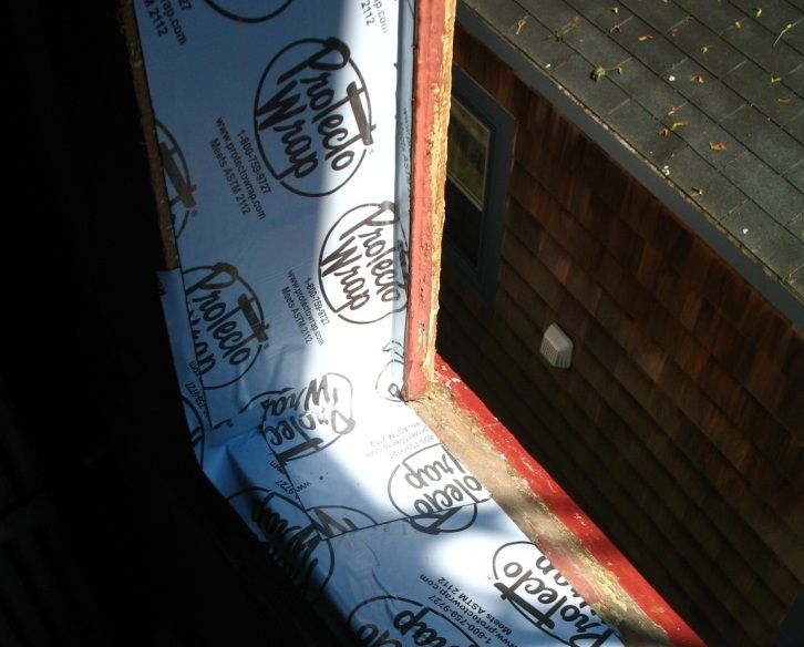
Measure Guideline:
Window Repair, Rehabilitation, and Replacement

                      Prepared for:
                    Building America
              Building Technologies Program
     Office of Energy Efficiency and Renewable Energy
                U.S. Department of Energy

                       Prepared by:

                     P. Baker, P. Eng.
               Building Science Corporation
                     30 Forest Street
                  Somerville, MA 02143

        NREL Technical Monitor: Cheryn Metzger
     Prepared under Subcontract No. KNDJ-0-40337-00

                     December 2012

                            iii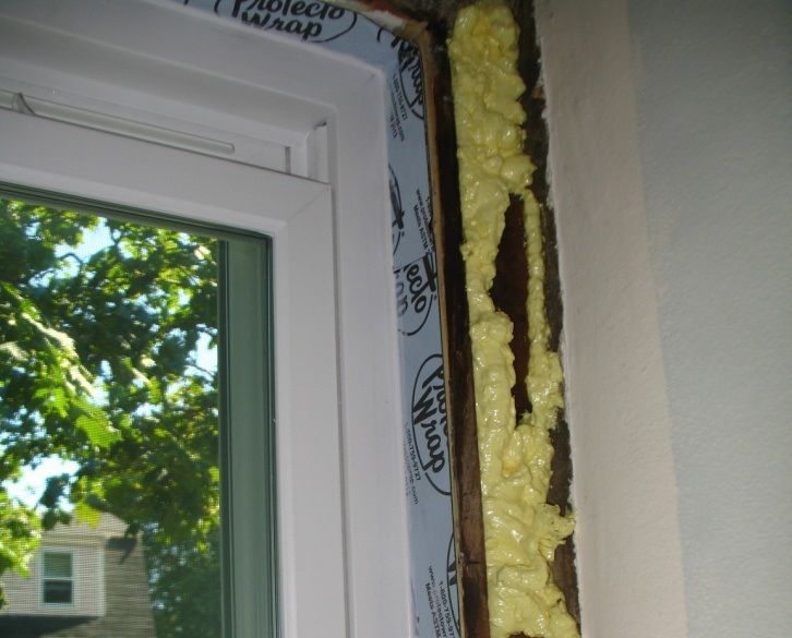
[This page left blank]

          iv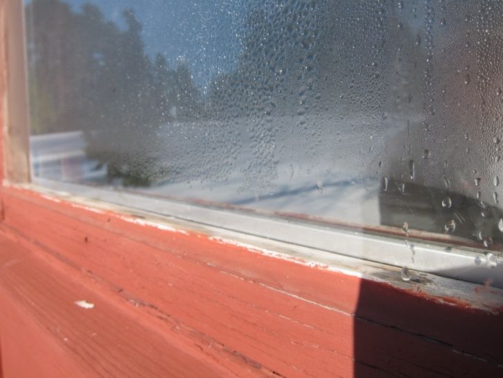
Contents
List of Figures ............................................................................................................................................ vi
List of Tables ............................................................................................................................................. vii
Definitions ................................................................................................................................................. viii
Executive Summary ................................................................................................................................... ix
Progression Summary ............................................................................................................................... xi
1 Introduction ........................................................................................................................................... 1
2 Decision-Making Criteria ..................................................................................................................... 4
      2.1 Risk Identification................................................................................................................4
          2.1.1 Lead and Other Hazardous Materials ......................................................................4
          2.1.2 Site Conditions and Project Staging ........................................................................4
          2.1.3 Identification of Water Infiltration Concerns ..........................................................4
          2.1.4 Identification of Deteriorated or Damaged Materials ..............................................6
          2.1.5 Identification of User Comfort Concerns ................................................................7
      2.2 Cost and Performance ..........................................................................................................7
3 Technical Description ............................................................................................................................ 10
      3.1 System Interaction .............................................................................................................10
          3.1.1 Window Water Management Functions ................................................................11
          3.1.2 Window Air Leakage .............................................................................................13
          3.1.3 Interstitial Condensation ........................................................................................17
          3.1.4 Window Thermal Performance ..............................................................................18
      3.2 Measure Selection Criteria .................................................................................................21
          3.2.1 Measure 1: Window Rehabilitation .......................................................................22
          3.2.2 Measure 2: Exterior Storm Windows ....................................................................22
          3.2.3 Measure 3: Interior Removable Storm Windows ..................................................23
          3.4.4 Measure 4: Interior Permanent Fixed Storm Windows .........................................24
          3.2.5 Measure 5: Window Sash Modification ................................................................25
          3.2.6 Measure 6: Window Sash Replacement ................................................................26
          3.2.7 Measure 7: Insert Replacement Window ...............................................................27
          3.2.8 Measure 8: Complete Window Replacement ........................................................28
4     Measure Implementation ................................................................................................................... 30
      4.1 Measure 1: Window Rehabilitation ...................................................................................30
      4.2 Measure 2: Exterior Storm Windows ................................................................................31
      4.3 Measure 3: Removable Interior Storm Windows ..............................................................33
      4.4 Measure 4: Permanent Interior Storm ................................................................................33
      4.5 Measure 5: Window Sash Retrofit .....................................................................................34
      4.6 Measure 6: Window Sash Replacement ............................................................................35
      4.7 Measure 7: Insert Replacement Window ...........................................................................36
      4.8 Measure 8: Complete window replacement .......................................................................39
          4.8.1 Window Replacement as Sole Scope of Work ......................................................39
          4.8.2 Window Replacement in Conjunction With a Siding Replacement ......................41
          4.8.3 Window Replacement in Conjunction With an Exterior Insulation Retrofit .........41
References ................................................................................................................................................. 43
Appendix A:        Window Repair, Rehabilitation, and Replacement Details ....................................... 44
Appendix B:        BEOPT Analysis Graphs .............................................................................................. 79

                                                                               v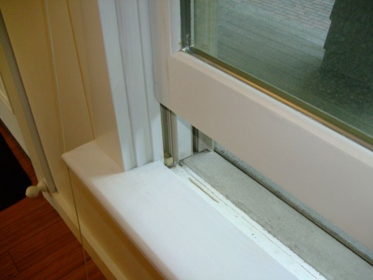
List of Figures
Figure 1. Glazing type (single, double, triple) by climate region ........................................................... 1
Figure 2. Window replacement history by climate region ...................................................................... 1
Figure 3. Impact of window U-value on effective thermal resistance of complete wall assemblies .. 2
Figure 4. Common window water infiltration pathways .......................................................................... 5
Figure 5. Failed window sill with replacement window installed ........................................................... 6
Figure 6: Example of BEopt analysis graph ............................................................................................. 8
Figure 7. Window components ................................................................................................................ 10
Figure 8. Window head component lapping........................................................................................... 11
Figure 9. Window jamb component lapping........................................................................................... 12
Figure 10. Wood window sill on top of masonry sill ............................................................................. 12
Figure 11. Window sill component lapping ............................................................................................ 13
Figure 12. Window air leakage pathways ............................................................................................... 14
Figure 13. Infrared images of window air leakage (depressurization test). Dark colored areas
indicate cold surface temperatures from cold outdoor air leaking into the building.................. 14
Figure 14. Infrared images of window air leakage (depressurization test). Dark colored areas
indicate cold surface temperatures from cold outdoor air leaking into the building.................. 15
Figure 15. Window to wall interface air leakage pathways ................................................................... 15
Figure 16. Infrared images of window air leakage at window interior apron trim. Dark colored areas
indicate cold surface temperatures from cold outdoor air leaking into the building.................. 16
Figure 17. Sash weight pockets .............................................................................................................. 16
Figure 18. Abandoned sash weight and insulation installation ........................................................... 16
Figure 19. Examples of condensation problems with interior storm window retrofits ..................... 17
Figure 20. Examples of condensation problems with interior storm window retrofits ..................... 18
Figure 21. Window energy transfer components................................................................................... 19
Figure 22. Areas of energy transfer affected by the addition of exterior storms ............................... 20
Figure 23. Window U-value and SHGC for various windows systems and exterior storm
configurations (Windows Energy Savings Estimator (2011) ......................................................... 21
Figure 24. Interior removable storm window sample ............................................................................ 22
Figure 25. Interior removable storm window sample ............................................................................ 23
Figure 26. Installed interior removable storm window .......................................................................... 23
Figure 28. Interior storm window on double-hung original window .................................................... 24
Figure 29. Interior storm window on double-hung original window .................................................... 24
Figure 30. Interior storm detail ................................................................................................................ 25
Figure 31.Window sash modification...................................................................................................... 25
Figure 32. Sash replacement, showing out of square opening and requirement for sash
extension ............................................................................................................................................. 26
Figure 33. Window sash replacement jamb liners ................................................................................. 26
Figure 34. Insert replacement vinyl frame window ................................................................................ 27
Figure 35. New window rough opening framed with and extension box to allow for the addition of
exterior insulation............................................................................................................................... 29
Figure 36. Recommended sealant location as part of window frame rehabilitation .......................... 31
Figure 37. Exterior aluminum storm windows, showing weep channel .............................................. 32
Figure 38. Condensation potential for exterior storm retrofits ............................................................ 32
Figure 39. Condensation potential for interior storm retrofits ............................................................. 33
Figure 40. Example sill detail for a permanent interior storm window ................................................ 34
Figure 41. Integration of an IGU into a wood sash ................................................................................ 35
Figure 42. Frame preparation for replacement window sashes ........................................................... 36
Figure 43. Example jamb detail for a replacement window sash ......................................................... 36
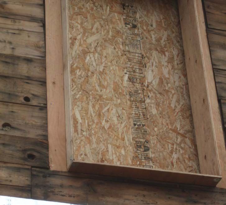
Figure 44. Frame preparation for insert replacement window ............................................................. 37
Figure 45. Examples of membrane installation in a wood window frame ........................................... 38
Figure 46. Example sill detail of insert replacement window ............................................................... 38
vi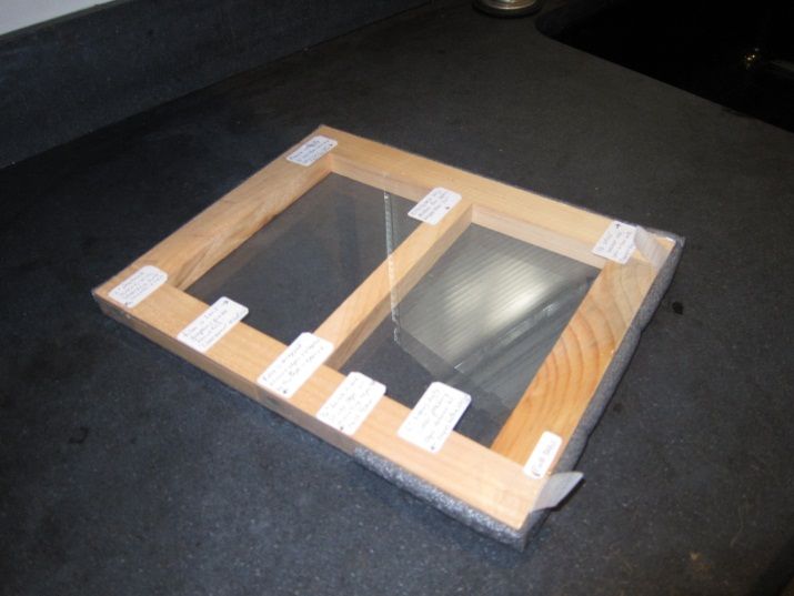
Figure 47. Replacement window rough opening preparation .............................................................. 40
Figure 48. Example sill detail for window replacement without siding replacement......................... 40
Figure 49. Example sill detail of replacement window in conjunction with siding replacement ...... 41
Figure 50. Example sill detail of "innie" window ................................................................................... 42
Figure 51. Example sill detail of "outie" window ................................................................................... 42
Figure 52. Annualized energy related costs versus average source energy savings for Dallas...... 79
Figure 53. Average source energy savings reduction for Dallas ......................................................... 79
Figure 54. Annualized energy related costs versus average source energy savings for
   Kansas City ......................................................................................................................................... 80
Figure 55. Average source energy savings reduction for Kansas City............................................... 80
Figure 56. Annualized energy related costs versus average source energy savings for Boston .... 81
Figure 57. Average source energy savings reduction for Boston ....................................................... 81
Figure 58. Annualized energy related costs versus average source energy savings for Duluth ..... 82
Figure 59. Average source energy savings reduction for Duluth ........................................................ 82

Unless otherwise indicated, all figures were created by BSC.

List of Tables
Table 1. Window Retrofit Measures ......................................................................................................... ix
Table 2. Window Performance Improvement Measures ......................................................................... 3
Table 3. Benchmark House Characteristics ............................................................................................. 8
Table 4. Parametric Steps and Cost for Climate Zones 4 and Above .................................................... 9
Table 5. Reference Cities............................................................................................................................ 9

Unless otherwise indicated, all tables were created by BSC.

                                                                           vii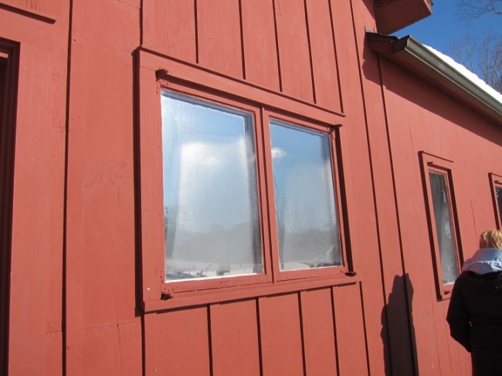
Definitions
ASHRAE        American Society of Heating, Refrigerating and Air-
              Conditioning Engineers
BA            Building America Program
BSC           Building Science Corporation
DOE           U.S. Department of Energy
IGU           Insulated glazing unit
NFRC          National Fenestration Rating Council
SHGC          Solar heat gain coefficient
U-Value       Window Thermal Transmittance Value
UA            U-Value multiplied by assembly area
WRB           Water resistive barrier

                                        viii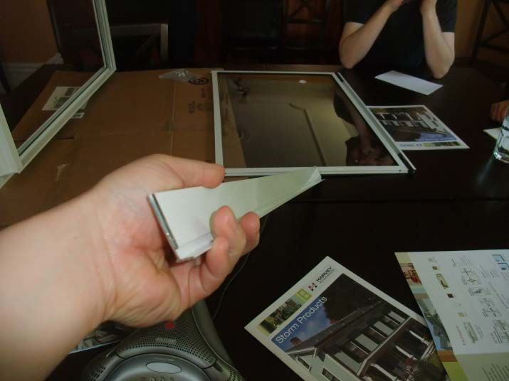
Executive Summary
There is a significant push for energy performance upgrades to existing homes. An important
target is often the windows. Old single-glazed windows have such low thermal resistance that
their effect on the overall thermal resistance of the walls can be staggering. Improving the
performance of the window stock is therefore central to the goal of reducing the energy
consumption of the existing building stock.
This measure guideline provides information and guidance about rehabilitating, retrofitting, and
replacing wood window assemblies in residential construction. It is intended primarily to help
contractors and homeowners understand the options for safely improving the performance of
their wood windows.
Deciding which window measure will be most appropriate for the retrofit project depends on
several factors, including current conditions, desired appearance or aesthetic goals, energy
performance goals, cost, disruption to occupants, durability risks, historic requirements, and any
other project goals or requirements.
Table 1 lists the f most common approaches to improve the performance of wood windows:
                                Table 1. Window Retrofit Measures

          Measure                                      Description
                          Repair/rehabilitation of the old window sashes, leaving the original
                          wood window frame in place. Frame and sash rehabilitation to
          Window
  1                       improve water management and air infiltration performance. Does
        rehabilitation
                          not improve conductance or solar gain. Cost can be highly variable
                          depending on window condition and extent of work needed.
                          Recommended installation practice for exterior storm windows,
                          including preparation of windows to accommodate storm windows.
       Exterior storm
  2                       Improves the air infiltration performance, conductance, and solar
         windows
                          gain. Additional benefits can be achieved with hard coat low-e
                          glazing. Cost is relatively low.
                          Recommended installation practice for removable interior storm
          Interior        windows, including preparation of windows to accommodate storm
  3   removable storm     windows. Improves the air infiltration performance, conductance, and
         windows          solar gain. Condensation potential on outer prime window could be a
                          durability concern. Cost is relatively low.
                          Recommended installation practice for permanent interior storm
                          windows, including preparation of windows to accommodate storm
          Interior
                          windows. Improves the air infiltration performance, conductance, and
  4   permanent storm
                          solar gain. Condensation potential on outer prime window could be a
         windows
                          durability concern. Cost is moderate to high compared to other
                          measures, depending on options chosen.

                                                ix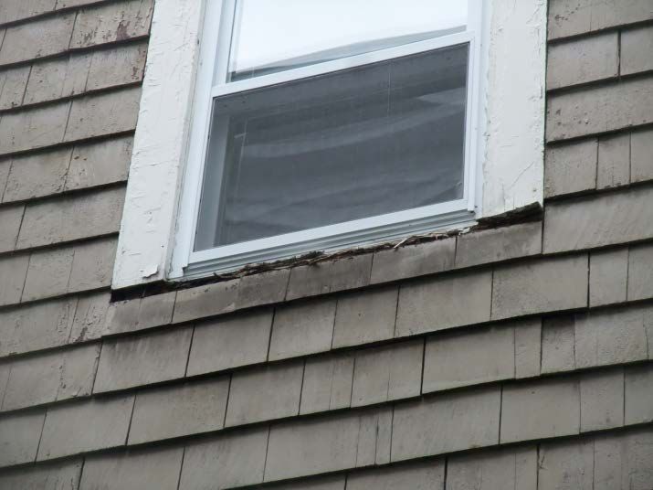
Measure                                    Description
                         Modification of the old window sashes, leaving the original wood
                         window frames in place. Frame preparation to accommodate original
        Window sash      sashes to accept high performance insulating glass units. Improves
  5
        modification     the air infiltration performance, conductance, and solar gain and
                         maintains the original appearance of the windows. Cost can be
                         moderate to high compared to other retrofit measures.
                         Removal of the old window sashes, leaving the original wood
                         window frames in place. Frame preparation to accommodate high
        Window sash      performance replacement sashes and tracks. Improves the air
  6
        replacement      infiltration performance, conductance, and solar gain and maintains a
                         similar appearance of the windows. Cost can be moderate to high
                         compared to other retrofit measures.
                         Removal of the old window sashes and reconfiguration of window
                         frame to accommodate a replacement window installed in the wood
           Insert        window frame. Improves the air infiltration performance,
  7     replacement      conductance, and solar gain. Work can be done quickly with little
          window         disruption to the occupants. Cost can be moderate to high compared
                         to other retrofit measures, depending on performance of replacement
                         window chosen.
                         Removal of the old window, including frame, and reconfiguration of
                         the rough opening to accommodate a new high performance window
                         following current recommended water management installation
         Complete
                         techniques. Improves the air infiltration performance, conductance,
  8       window
                         and solar gain. Provides the most control over the window size,
        replacement
                         location, placement, and integration with other enclosure retrofit
                         measures. Cost is high compared to other retrofit measures and is
                         typically a significant disruption to the building occupant.

Complementary information about a variety of energy upgrades can also be found in the National
Renewable Energy Laboratory’s Standard Work Specifications, currently under development
through U.S. Department of Energy’s Guidelines for Homes Energy Professionals project.

                                              x
Progression Summary
ss The following outlines the steps to consider when looking to repair, rehabilitate, or
WOOD WINDOW replace wood windows in a home.
OPTIONS
1
Evaluate building conditions. Review the building conditions for
any hazards or anything that needs to corrected before the work
starts,
EVALUATE
WINDOWS
Do Not Proceed If:
! • Lead paint is present or suspected on the window or
window frame.
• Water is intruding from sources other than the window.
!
2
Review site conditions and project staging. Examine the
property to identify impacts and risks associated with performing
the work.
REVIEW SITE
CONDITIONS
SITE CONDITIONS
!
Do Not Proceed If:
! • Site conditions create unsafe work environments.
3
Indentify performance concerns. Review the current
performance problems (water infiltration, air leakage, energy, etc.)
and rank them to determine the project goals.
IDENTIFY GOALS
Select the window retrofit measure. Choose the most
4 appropriate window retrofit measure to address the identified
performance concerns that stays within the budget.
SELECT MEASURE
xi1 Introduction
There is a significant push for energy performance upgrades to existing homes. An important
target is often the windows. Poor window performance can have significant impacts on the
overall thermal resistance and airtightness of the home. The existing U.S. housing stock has a
wide range of window types (Figure 1), ages, and conditions. All are factors in the overall energy
performance and comfort performance of the home. Most windows are still original to the
homes; however, it is not uncommon for windows to be replaced (Figure 2). Possibly more
common than window replacement are attempts at lower cost window retrofits. These retrofits
have often been done (with varying degrees of success) by homeowners trying to address
problems without adequate knowledge about how to safely, effectively, and economically
address the problems.
45
40
Millions of US Households
35 Triple-pane
30 Double-pane
25 Single-pane
20
15
10
5
0
Figure 1. Glazing type (single, double, triple) by climate region
(EIA 2009)
45
40
Millions of US Households
35 None
30 Some
25 All
20
15
10
5
0
Figure 2. Window replacement history by climate region
(EIA 2009)
1Old single-glazed windows have such low thermal resistance that their effect on the overall
thermal resistance of the walls can be staggering. A simple UA 1 analysis that compares the total
wall effective R-value to the window U-value for opaque wall assemblies of varying effective R-
values shows how significant this impact can be (Figure 3).
Figure 3. Impact of window U-value on effective thermal resistance of complete wall assemblies
Older windows typically represent a significant portion of the total house air infiltration. The
combined effect of poor thermal performance and air infiltration results in windows being a
major component to total energy use. Improving the performance of the window stock is
therefore central to the goal of reducing the energy consumption of the existing building stock.
Table 2 provides information and guidance about rehabilitating, retrofitting, and replacing wood
window assemblies in residential construction. The intent is to provide information about means
and methods to improve the energy and comfort performance of wood window assemblies in a
way that considers component durability, in-service operation, and long-term performance. This
guideline focuses on proper detailing of strategies to provide a visual reference for how to
properly implement these recommendations.
This measure guideline is primarily intended to help contractors and homeowners understand the
options for safely improving the performance of their wood windows. The details are simple,
clear, and provide specific information about building condition review, material preparation,
installation, and other considerations that would not normally be explained in a general retrofit
recommendation.
1 The UA analysis multiplies an individual component U-value by its associated area to create an area weighted
thermal transmittance value.
2Table 2. Window Performance Improvement Measures
Measure Description
Repair/rehabilitation of the old window sashes, leaving the
Window original wood window frames in place. Frame and sash
1
Rehabilitation rehabilitation to improve water management and air infiltration
performance.
Recommended installation practice for exterior storm windows,
Exterior storm
2 including preparation of windows to accommodate storm
windows
windows.
Recommended installation practice for removable interior storm
Interior removable
3 windows, including preparation of windows to accommodate
storm windows
storm windows.
Recommended installation practice for permanent interior storm
Interior permanent
4 windows, including preparation of windows to accommodate
storm windows
storm windows.
Modification of the old window sashes, leaving the original
Window sash wood window frames in place. Frame preparation to
5
modification accommodate original sashes to accept high performance
insulating glass units (IGUs).
Removal of the old window sashes, leaving the original wood
Window sash
6 window frames in place. Frame preparation to accommodate
replacement
high performance replacement sashes and tracks.
Removal of the old window sashes and reconfiguration of
Insert replacement
7 window frames to accommodate replacement windows installed
window
in the wood window frames
Removal of the old window, including frame, and
Complete window reconfiguration of the rough opening to accommodate a new
8
replacement high performance window, following current recommended
water management installation techniques.
Do-it-yourself homeowners (as opposed to professional contractors) are likely to use this
information: therefore, it is important that clear information about means and methods be
provided, so that retrofits can be executed in a manner which will promote long term durability
of the building enclosure systems.
Complementary information about a variety of energy upgrades can also be found in the National
Renewable Energy Laboratory’s (NREL) Standard Work Specifications, currently under
development through the U.S. Department of Energy’s (DOE) Guidelines for Homes Energy
Professionals project.
32 Decision-Making Criteria
Contractor/Homeowner Safety
2.1 Risk Identification
Before any retrofit work is conducted, i the U.S. Environmental Protection Agency:
conditions of the building systems must be Lead in Paint, Dust, and Soil:
Renovation, Repair and Painting
reviewed. www.epa.gov/lead/pubs/renovation.htm
2.1.1 Lead and Other Hazardous Materials Occupational Safety and Health
Lead is commonly located on old wood windows Administration: Fall Protection (if window
work is to be done at height, from the
and trim. Any work being completed on the exterior) www.osha.gov/
window systems should follow all state and federal SLTC/fallprotection/index.html
laws for handling hazardous materials.
2.1.2 Site Conditions and Project Staging
The home and site should be reviewed to identify impacts and risks associated with completing
the work.
Scaffolding, lifts, ladders, or other means to access work areas may be needed if the work is to
be done on the exterior. Work done at height may require fall protection. Proximity to adjacent
property or vegetation may limit access or create unsafe work areas. Exterior staged work may
also damage landscaping or vegetation.
If the work will be done from the interior, consideration should be given to disruptions to the
occupants and clearances for moving equipment and materials into and out of the space. Interior
work always poses a risk of damage to interior finishes. Planning and protection are required.
2.1.3 Identification of Water Infiltration Concerns
Windows are the most common location of water infiltration issues. It is important to understand
the various pathways for potential water infiltration, and identify current water leakage problems.
Although the details presented in this guideline are all intended to improve the moisture
performance of the window assemblies, the guideline is not intended to address all possibilities,
and is not a replacement for inspection and evaluation of the performance of an individual
window. Problems should be identified, and the strategy chosen that will be most appropriate to
address the concern. Window systems water leaks can be grouped in four general categories
(Figure 4):
• Between the window frame and rough opening
• Through the joints in the window frame
• Between the window frame and the operable sashes
• Through the joints between the glass and the sash frames.
4Between the frame and rough
opening
At joints in the frame
Between the sash and frame
Between the glass and sash
Figure 4. Common window water infiltration pathways
Interior and exterior inspection and monitoring of the building conditions should be completed
before any work is started. Water staining, peeling paint or wall paper, and staining on trim or
floor assemblies below window systems indicate water infiltration and/or condensation. Leakage
between the sashes and the frame and between the glass and the sash is usually marked by water
staining on the interior window frame. Condensation on the window frames can also lead to
staining of the interior finishes. It is important to monitor the questionable area to prevent a false
diagnosis of the water management problem.
Leakage between the window and the rough opening or through the joints in the window are
typically contained within the wall assembly and may go unnoticed, or could manifest as staining
and peeling paint below the window or damaged flooring.
Other problems such as water infiltration at the window head may be indications of failed or
missing head flashing. However, other problems not associated with the window system may
cause the water infiltration. Care must be taken to properly diagnose the infiltration pathway.
If it is a known recurring problem, the infiltration problem must be addressed prior to, or in
conjunction with, the window retrofit work.
If there are no obvious signs of water infiltration problems and the window elements and
connection wall components are in good condition, no additional work may be needed. However,
water infiltration problems are often concealed within wall cavities. This becomes a greater
concern if the window retrofit work is being done in conjunction with the addition of cavity fill
insulation, because a cavity that may have had sufficient drying ability may now have prolonged
moisture accumulation that can lead to material deterioration. If leakage is suspected, further
investigation, including thermal scans, moisture content measurements, and cutting of
5investigation holes below window assemblies to look for signs of moisture problems are
recommended.
Unless the problem is obvious, it may be prudent to contact someone with experience diagnosing
water infiltration problems before proceeding.
2.1.4 Identification of Deteriorated or Damaged Materials
Damaged materials should be removed and replaced as part of the retrofit. Certain elements will
be more critical to the proper implementation of the chosen strategy.
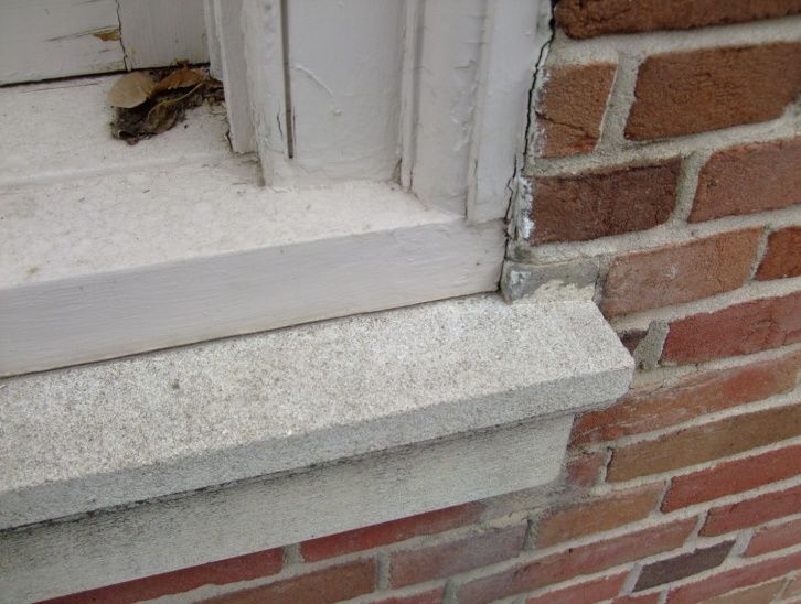
The window sill is arguably the most important element of the window assembly, as water will
drain downward by gravity either into the wall (e.g., hole through sill) or directly onto the wall
(failure of the sill extension). For all proposed measures in this guideline (except complete
window replacement), the condition of the sill is critical to the performance of the measure.
Cracked or rotting sills need to be replaced before any work is done (see Figure 5).
Figure 5. Failed window sill with replacement window installed
The window frame, including the exterior casings, is the next most critical element. If the casing
is deteriorating, its replacement may be warranted. This should not be confused with the exterior
trim, which is often installed as a decorative element on top of the casing. Deteriorating trim may
not affect the water management performance of the window; however, it may be an indication
of other problems and generally creates an aesthetic problem.
Depending on the measure being examined, the condition of the window sashes may or may not
be a concern to the performance of the measure. For window rehabilitation, sash retrofit, or
interior storm window retrofit, the condition of the sashes is critical to the performance of the
window. For exterior storm windows, the sashes are more protected from the elements, and the
condition is less important from a water management perspective, yet still critical from an energy
and condensation resistance perspective. For sash replacement, window insert, or full window
replacement, the condition of the sash is irrelevant, as they will be removed. Thus, windows with
severely deteriorated sashes may be better candidates for the latter retrofit measures.
62.1.5 Identification of User Comfort Concerns
As part of the initial review, comfort concerns related to the window systems should be
evaluated. Window air leakage is a significant source of occupant comfort problems. Unlike
other common enclosure leakage pathways, window air leakage is commonly very direct,
resulting in distinct drafts.
Radiation effects from cool glass surfaces are another common comfort problem. This is more
difficult to identify, as many people assume that the discomfort felt when near a window is from
air leakage or drafts. This results in some misdiagnosis of the dominant function. A general
recommendation is to increase the interior surface temperature of the window system to reduce
the radiant heat transfer from the occupant to the window. This is commonly done by adding
additional panes of glass (or films) to create an insulating air (or other gas) space between the
layers.
2.2 Cost and Performance
The cost effectiveness of a window retrofit will depend on numerous factors, though possibly
most critical is the existing window performance. Single-glazed wood windows have
proportionally very poor performance compared to other glazing systems (U = 0.87, solar heat
gain coefficient [SHGC] = 0.62). If the baseline begins from this point, almost any window
retrofit strategy will provide a cost justifiable improvement to the current conditions.
A preliminary evaluation was completed looking at the cost versus energy performance of
several wood window retrofit measures. Cost data for the windows were taken from several
sources, including averages based on direct quotes from manufacturers for multiple product lines
and from RS Means Construction Data (2011 Reed Construction Data). Product costs vary
widely, so estimated averages were used to develop a representative sample. For each project,
specific cost analysis will be required to ensure the cost effectiveness.
Simulations were run using BEopt simulation software developed by NREL (see Figure 6). The
analysis examines the cost effectiveness of the window system upgrades by comparing the
annualized cost of each measure over the analysis period (assumed at 30 years for this analysis)
compared to the estimated annualized utility savings. The costs displayed in the cost/energy
graphs (Appendix B) are full annualized utility bills plus incremental annualized values for other
cash flows such as mortgage/loan payments, replacement costs, and residual values of the
measure being implemented. A measure is determined to be economically justifiable if its total
annualized cost is less than the total annualized cost of the baseline (in this case, the original
wood windows). The cost optimized solutions have the lowest total annualized cost.
7Total annualized cost of single-glazed
wood windows
Points below this line indicate an
economically justifiable retrofit
measure compared to the baseline
single-glazed wood window
Lowest point represents the cost
optimized retrofit measure
Figure 6: Example of BEopt analysis graph
An example home was used as the baseline to help demonstrate the benefits of using exterior
insulation as part of a house energy retrofit (see Table 3). This benchmark home was assumed to
be a 1950s era two-story slab-on-grade construction.
Table 3. Benchmark House Characteristics
House Characteristics Square Feet
Finished Floor Area 2312
Ceiling Area 1156
Slab Area 1156
Wall Area 2799
Window Area 410 (17.7% glazing ratio)
The window performance was isolated from all other aspects of the home to examine the
effectiveness of this single strategy. The baseline window was chosen to be a double-hung,
single-glazed wood window. In addition to the performance changes in both the U-value and the
SHGC, increases in airtightness were also included as part of the analysis. Levels of increased
airtightness were estimated because measured data relating specifically to window airtightness
increases were lacking.
The following parametrics were run to see the effectiveness of the various window retrofit
strategies to the energy performance and utility cost (Table 4).
8Based on general assumptions, most measures chosen (other than triple-glazed replacement
windows) in all climate zones were economically justifiable when the baseline windows were single-
glazed wood. However, costs vary widely, so project-specific costs and analysis will be required to
determine the cost effectiveness of the measure for each project.
Table 4. Parametric Steps and Cost for Climate Zones 4 and Above
Parametric Step Cost/ft2
Benchmark = single glazed wood N/A
(U = 0.87, SHGC = 0.62)
Single-glazed wood + clear exterior storm $7.81
(U = 0.49, SHGC = 0.60)
Single-glazed wood + low-e exterior storm $12.14
(U = 0.40, SHGC = 0.52)
Double-glazed low-e ENERGY STAR® window $40.73
(U = 0.30, SHGC = 0.30)
Single-glazed wood + interior double-glazed low-e $40.73
ENERGY STAR window
(U = 0.25, SHGC = 0.25) 2
Triple-glazed low-e window $77.76
(U = 0.20, SHGC = 0.20)
Simulations were run for the following cities (Table 5):
Table 5. Reference Cities
City Climate Zone
Dallas, Texas 3A
Kansas City, Missouri 4A
Boston, Massachusetts 5A
Duluth, Minnesota 7A
Results indicated that most strategies chosen in all climate zones were economically justifiable
when the baseline windows were single-glazed wood. The exterior clear storms and low-e storm
windows provided the cost optimized solutions for colder climates. However, in Dallas a much
narrower gap between the storm windows and the window replacements was noted. This is partly
because the overall storm window performance has a lesser effect on the single-glazed wood
framed window, and partly because Dallas is in a cooling-dominated climate that is affected
predominantly from SHGC and not U-value. In none of the analyses were triple-glazed windows
demonstrated to be economically justifiable.
2
Values were assumed due to unavailability of actual modeled or measured values for this configuration
93 Technical Description
3.1 System Interaction
It is important to understand the system components and connection/interaction details with the
wall enclosure, as well as the functions of a traditional wood window, to properly apply the
various measure recommendations (see Figure 7).
Header
Sheathing
Head flashing
Stop
Parting bead
Exterior casing
Interior trim/casing
Exterior trim
Upper sash
Muntin
Meeting rails
Weight pocket
Lower sash
Studs
Stool
Sill
Apron
Sill framing
Sheathing
Siding
Figure 7. Window components
103.1.1 Window Water Management Functions
Traditional double-hung wood windows function by shingle lapping the various components of
the window assembly (including its surrounding trim components).
For wood-framed walls, a metal flashing is common at the window head to shed water from the
siding out over the face of the trim and exterior window casing. The casing is shingle lapped
over the upper sash. The upper sash is always installed outboard of the lower sash. The lower
sash sits on the window sill. The window sill projects out over top of the siding or cladding
element (Figure 8).
Siding
Head flashing
Head trim
Window casing
Upper sash
Figure 8. Window head component lapping
At the jambs, the water management is generally from a similar concept of overlapping of
materials. The wall siding overlaps onto the exterior window casing, and the casing overlaps the
sashes. The lapping at the jambs cannot wholly rely on gravity to prevent water from infiltrating
into the enclosure, so sealants are often used between the siding and the window trim to limit the
potential for infiltration.
11Wall sheathing
Window casing
Window trim
The siding and exterior window casing are
typically installed in an overlapped manner.
This provides some protection against direct
water infiltration; however the joint is still
often reliant on sealant at the trim to siding
interface.
Siding
Figure 9. Window jamb component lapping
Similar approaches are used in mass masonry walls with a few slight changes to the concept. At
the window head, the window frame is set back from the face of the masonry (approximately one
layer of brick), so the head flashing is traditionally eliminated. At the jambs, the window casing
either butts directly up against the brick, or is overlapped by the outer layer of brick with the
joint caulked (Figure 10). The sill is shingle lapped over a stone, concrete, or brick sill. The
masonry sill is usually sloped to the exterior.
Figure 10. Wood window sill on top of masonry sill
12Wood sills are traditionally continuous with the
jamb framing, casing and trim all installed over top
of the sill
This configuration promotes drainage to the
exterior even if there is a failure in a seal at the sill
to jamb interface or higher up in the window frame
Figure 11. Window sill component lapping
The continuous sloped wood sill is a critical element to the performance of wood windows. The
sill significantly protects the wall assemblies below. In essence, the wood sill acts similarly to a
sloped pan flashing that is part of current recommended new construction practice (Figure 11). In
some cases, a pan flashing may have been installed below the window frame; however, this is by
no means guaranteed for all construction, and tends to be more common for masonry buildings
than for wood-framed buildings. Unfortunately, these subsill flashings often deteriorate over
time and lose their effectiveness.
The condition of the wood window frame is critical to the water management performance for all
proposed measures except complete window replacement. Damaged or deteriorating window sills
must be repaired or replaced.
3.1.2 Window Air Leakage
There are multiple pathways for air leakage through a window frame. The most common are
between the meeting rails (where the upper and lower sashes interface), and between the sashes
and the frame (Figure 12 through Figure 14). These are the operable elements of the window, so
they typically cannot be too tight, as this would affect operation. In addition, repetitive operation
results in a wearing of materials at the interface, increasing dimensional tolerances. In addition to
the meeting rail and jamb air leakage, leaks can also be found at the head and sill.
13Air infiltration between sash and frame
Air infiltration at the meeting rails
Figure 12. Window air leakage pathways
Figure 13. Infrared images of window air leakage (depressurization test). Dark colored areas
indicate cold surface temperatures from cold outdoor air leaking into the building.
14Figure 14. Infrared images of window air leakage (depressurization test). Dark colored areas
indicate cold surface temperatures from cold outdoor air leaking into the building.
A typical window installation has void spaces between the frame and the rough opening. The
gaps are also common areas of uncontrolled air leakage; however, the pathway is less direct, and
therefore less significant from a user comfort perspective (Figure 15 and Figure 16).
Void created by weight pockets at window jambs
Void below window sill due to frame geometry
Figure 15. Window to wall interface air leakage pathways
15These voids are typically disconnected from the framing cavities of wood-framed walls, and
therefore would not be filled during common cavity fill insulation retrofits such as blown-in
cellulose. Specific measures need to be taken to address the air leakage pathway and associated
concerns of conductance losses.
Figure 16. Infrared images of window air leakage at window interior apron trim. Dark colored areas
indicate cold surface temperatures from cold outdoor air leaking into the building.
The largest of the voids are typically at the weight pockets created to house the sash
counterweights (see Figure 17 and Figure 18). The weights are connected to the sashes through
either ropes or chains that run from the sash to a pulley near the top of the window jamb and into
the weight pocket. When combined with an interior storm window (both temporary and
permanent), the pulley weight pockets can create a condensation potential (discussed in Section
3.1.3), as they are a pathway for movement of interior air into the space between the old window
and the new interior glazing element. Often, the sash weights can be eliminated by retrofitting
the windows a spring-loaded tape balance. Abandoned weight pockets permit energy loss from
conductance and from uncontrolled air leakage. Even when they are insulated, it is often done in
a “blind” manner (inserting insulation through an access hole in the jamb), resulting in poor
installation quality.
Figure 17. Sash weight pockets Figure 18. Abandoned sash weight and
insulation installation
16The spaces should be filled with spray polyurethane foam to address these concerns. The weights
should be removed before the void is filled. In addition to the weight pockets, there are typically
gaps between the window frame and the rough opening at the head and sill. These voids should
also be filled.
Air leakage associated with window systems is from two general sources: (1) leakage through the
window system (such as between the frame and sashes); and (2) leakage between the frame and
the rough opening. Most of the measures only directly impact the leakage through the frame.
Consideration should be given to the spaces between the frame and the rough opening when
planning the retrofit. Abandoning and insulating weight pockets can have a significant effect on the
overall performance.
3.1.3 Interstitial Condensation
The addition of interior or exterior glazing elements to the original window creates a potential
for the formation of condensation between the two glazing elements. The placement of the
interior or exterior of the window creates an insulating air pocket, resulting in the outer glazing
element to be at a lower temperature at wintertime conditions. This increases the chance of
condensation forming, if interior moisture laden air can infiltrate the space.
Figure 19. Examples of condensation problems with interior storm window retrofits
17Figure 20. Examples of condensation problems with interior storm window retrofits
Condensation at exterior storm windows is typically not a durability concern, but mostly an
operational and aesthetic concern, as it disrupts clear vision to the outside. The exterior storm
windows are typically made of moisture-insensitive materials (aluminum extrusions).
Retrofit of interior storm windows can pose a durability risk: if there is air leakage, the
condensation will occur on the “prime” window, which is often part of the historical fabric of the
house, and is made of moisture-sensitive materials such as wood (Brown 1997). Therefore,
airtightness of interior storm windows is crucial in
cold climate installations.
Research shows that a small amount of ventilation Airtightness of interior storm windows
of the space with dry air can mitigate condensation is of vital importance in cold climate
installations. Condensation that could
concerns (Wilson 1960). Therefore, in cold climates occur on the existing (“prime”)
it is important that the inner glazing element be as window can create a durability risk,
airtight as possible to reduce air infiltration into the as the window is made of moisture-
void space. Air bypass of the glazing elements must sensitive materials.
also be considered and addressed.
3.1.4 Window Thermal Performance
Energy is transferred across a window assembly by several mechanisms. Conduction, convection
(air movement such as air leakage), and radiation are all components of performance. With so
many materials (wood, polymers, glass, metal) being combined to create a window system, the
interactions between all these elements are not necessarily simple or straightforward (see
Figure 21).
18Conduction through wall framing
Convection (air leakage) through and within the void
Conduction through window frame
Convection (air leakage) between frame and sash
Conduction through sash
Convection (air leakage) between sash and glass
Conduction through glass
Radiation through glass
Absorption and emittance from glass
Convection (air leakage) between sash and glass
Conduction through sash
Convection (air leakage) between frame and sash
Conduction through window frame
Convection (air leakage) through and within the void
Conduction through wall framing
Figure 21. Window energy transfer components
Figure 21 is a simplification of the energy transfer through a window and its surrounding
enclosure elements. The actual energy transfer mechanisms are three dimensional, with all of the
mechanisms interacting and impacting the actual performance. To more closely quantify window
performance, extensive laboratory testing (or at minimum two-dimensional heat flow computer
simulation modeling) is generally required.
Knowing the general mechanisms can help a person understand how a certain measure will
modify the performance. Elements such as interior and exterior storm windows will impact
mechanisms such as the conductance through the glass and sashes, air leakage between the frame
and sashes or between the sashes and glass, and the radiation, absorption, and emittance from the
vision glazing elements (Figure 22).
19The exterior storm window creates a buffer of
still air between the original window and the new
storm window.
The exterior storm window will reduce the
radiation transfer, conductance transfer, and air
leakage of the sashes and sash-to-frame
interface.
The storm window does not significantly affect
conductance and air leakage through the
window frame (though flanking effects will have
some impact) or at the window-to-wall interface.
Figure 22. Areas of energy transfer affected by the addition of exterior storms
Until recently, information was available only about the energy performance of the window
system. However, new standards for rating fenestration attachment products have recently been
introduced by the National Fenestration Rating Council (NFRC 2010a, 2010b), to help quantify
the effects of various window coverings. The new standards will help to further quantify the
performance question of various strategies, though it may be some time before a significant
database of rated products is developed.
In the interim, some information is available to help in the determination. Some work
coordinated under the DOE’s High Performance Windows Volume Purchase Program assigned
20some values to various high performance windows and configurations of existing windows with
exterior storm windows (Figure 23).
Figure 23. Window U-value and SHGC for various windows systems and exterior storm
configurations (Windows Energy Savings Estimator (2011)
Although some general ranking of the expected performance improvements can be made, each
project should make its own evaluation of the expected performance to determine the best
approach.
3.2 Measure Selection Criteria
The energy performance of the window system involves all three modes of energy transfer
(conduction, convection, and radiation). Understanding the general mechanisms can help
understanding of how a certain measure will modify the performance. To more closely quantify
window performance, extensive laboratory testing (or at minimum two-dimensional heat flow
computer simulation modeling) is generally required.
Deciding which window measure will be most appropriate for the retrofit project depends on
several factors. The following is a list of the proposed measures and some key points to consider
with each.
213.2.1 Measure 1—Window Rehabilitation
The first measure looks to improve the window performance without significant modification or
addition. This measure has practically no impact on the appearance of the window as the
modifications are all concealed and minor. The work focuses around adding gaskets and seals at
common air infiltration locations to improve the overall airtightness of the window assembly.
Some methods are covered in detail by Davis (2007).
Key points:
1. Maintains both the interior and exterior appearance of the building (This is an important
strategy where historic preservation is required).
2. This work is best done in conjunction with other measure strategies, including interior and
exterior retrofit approaches (such as the addition of interior and exterior storms).
3. This work will improve the energy performance of the assembly by reducing air infiltration;
however it will not improve the thermal conductance of the window system.
4. This work will not address any current condensation problems that may be occurring on the
window system.
5. If sash weights are maintained, other potential energy and durability considerations may not
be addressed, such as air leakage and thermal conductance losses at weight pockets.
6. Cost can be highly variable depending on the size, complexity, condition, and value of the
windows.
3.2.2 Measure 2—Exterior Storm Windows
A common and long-standing window
retrofit approach is to add storm windows
to the exteriors of the frames. The most
common design is a triple-track window
that combines a screen with operable upper
and lower sashes. Traditionally, storm
windows have been single glazed with
clear glass, but more recently, hard coat
low-e glass has become available.
Figure 24. Interior removable storm window
sample
22You can also read