Modular and Compact 1 MW Inverter in one 19ʺ Rack for Storage and PV - NETfficient
←
→
Page content transcription
If your browser does not render page correctly, please read the page content below
Presented at the PCIM Europe 2017, May 16-18, 2017, Nürnberg
© 2017 VDE. This is the author’s version of an article that has been published in the conference
proceedings.
Modular and Compact 1 MW Inverter in one 19ʺ Rack for Storage
and PV
Patrick Hercegfi, patrick.hercegfi@ise.fraunhofer.de
Stefan Schönberger, stefan.schoenberger@ise.fraunhofer.de
Fraunhofer ISE, Heidenhofstr. 2, 79110 Freiburg, Germany
Abstract the same DC bus but via its own DC/DC convert-
er. The inverter hardware itself can not only be
During the EU funded project “NETfficient” the used as a bidirectional battery inverter but also as
low and medium voltage distribution grid of the a photovoltaic (PV) inverter in other setups.
North Sea island of Borkum will be upgraded by a
substantial amount of renewable energy and sev- Unlike PV central inverters, however, which are
eral storage solutions. For the medium voltage commonly built as monolithic two to three mega-
storage a highly compact bidirectional 1 MW bat- watt devices now, storage systems and thus bat-
tery inverter was built and will be presented here. tery inverters are often chosen for a specific load
With an eye on the finely scalable power ratings case which i.e. in industrial applications (PV self-
for storage inverters, a modular configuration with consumption) can change over time due to
eight 125 kVA units fitting into a single 19" rack changes in the machinery pool or its usage pat-
was chosen. New technologies like SiC MOSFET terns. A flexible solution is presented here, modu-
modules, high current PCBs, modular iron powder larizing the inverter and allowing resizing of the
chokes and cold plates resulted in compact plug- inverter at any time. By dynamically activating
in units with efficiencies up to 98.9 % despite the only the necessary amount of units, part load effi-
small size. ciency can be increased substantially.
Introduction
As part of the Horizon 2020 research and inno- 1. Hardware Description
vation programme funded by the EU, project
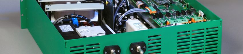
“NETfficient” aims to further develop energy stor- 1.1 Inverter System
age solutions for domestic, business and utility As the housing for the eight inverter units, a sin-
scale applications. A broad range of storage gle 19" rack (60x80x220 cm³ including base) is
technologies ranging from lithium-iron batteries, sufficient (Fig. 1). The weight without the cooling
supercapacitors and hydrogen to thermal storage system but including all inverter units is 590 kg
combined with heat pumps will be rolled out to the which results in total power densities of
installation site Borkum for field testing. All stor- 0.95 kVA / liter and 1.7 kVA / kg. These are by a
age nodes will be integrated into a smart grid and factor of two to four higher than comparable in-
controlled by an intelligent energy and grid man- verters on the market.
agement system. New business models will be
tested out and combined with existing use cases. In the back of the rack copper bus bars with a
One of the key results will be an energy man- nominal current of 1600 A run from the top –
agement platform supporting any storage tech- where they connect the DC and AC side of the
nology and business model with forecasts and inverter units in parallel – to the connection point
decision-support for the energy service company at the bottom. The coolant distribution is placed
(ESCO). next to the bus bars and separated from the units
by a sheet metal wall which holds the coolant
The utility scale part of the project will be a hybrid sockets. Connectors for communication, 230 V
energy storage system comprised of a lithium-iron auxiliary supply as well as signals to and from the
battery supported by a supercapacitor, feeding coolant system and the circuit breaker are placed
into the medium voltage grid via the inverter and on the front panel and are connected in parallel
a transformer. The 1 MVA inverter is directly con- across all units as well.
nected to the battery with a single high current
DC bus, while the supercapacitor is connected to
Fig. 2: Front view of a 125 kVA inverter unit for the
                                                              19” rack with 150 mm height

Fig. 1: Megawatt battery inverter in 19” technology
All connections for power and coolant are estab-
lished by simply pushing the units into the rack,
which means units can be easily be replaced (hot
swapping).
The inverter units are liquid cooled in combination
with an external heat exchanger. Air cooling
would lead to a derating of the system at extreme
conditions like high temperature or high altitude,
while this can be avoided by using a separate
liquid cooling system that can be dimensioned for     Fig. 3: Rear view with high current DC- and AC-
the specific conditions on the installation site.             connectors (left) and leakage free coolant con-
                                                              nectors (right)
1.2 Inverter Units
                                                      The recently available line of high current SiC
The units are housed in 19” cases which are
                                                      semiconductor modules made it possible to com-
150 mm in height, 490 mm in depth (without con-
                                                      bine high power with high switching frequency
nectors) and weigh 42.5 kg. (Fig. 2) At a nominal
                                                      without compromising on the efficiency. In this
power of 125 kVA this results in a high power
                                                      case three 1.2 kV, 300 A half bridge modules are
density of 3.70 kVA per liter and 2.94 kVA per kg.
                                                      used in a simple B6 topology with the battery
Each of the units has its own DC fuse as well as      voltage on the input and operated at 40 kHz to
DC and AC contactors, so it can completely dis-       make up the core of each of the single-stage in-
connect from the system if necessary.                 verter units.
The AC filter is comprised of a three phase choke     High switching speeds of up to 7.5 kA/µs and at
with cores made from modular iron powder pellets      peak currents of around 300 A require low induct-
and three power capacitors in star configuration      ances in the commutation cells to limit voltage
with the star point connected to the negative pole    overshoots. Laminated bus bars were therefore
of the DC link.                                       taken into consideration but calculations showed
                                                      that in this case a special thick copper PCB can
                                                      achieve similar results at lower cost (Fig. 4).
connected. The dynamically selected master is
                                                        responsible for distributing power demand intelli-
                                                        gently among the available units. Furthermore it
                                                        aggregates the states, measurement values, lim-
                                                        its, errors, etc. of all eight inverter units.

                                                              ESCO                 Inverter System

                                                                                     Inverter Unit 8
                                                               EMS
                                                                                      (dyn. Slave)

                                                                                     Inverter Unit 3
                                                              Battery
                                                                                      (dyn. Master)
Fig. 4: Power stack detail: Cold plate, SiC MOSFET
        module, high current PCB and film capacitors          Super-                 Inverter Unit 1
                                                               cap                    (dyn. Slave)
As this is a three-phase three-wire inverter with
symmetrical power output, there are almost no                                    external       internal
100 Hz and 150 Hz components to be buffered by                                   CAN Bus       CAN Bus
the DC link capacitors. The remaining switching
ripple was thus be realized by a film capacitor         Fig. 5: CAN communication with inverter unit 3 auto-
bank with very low ESR and ESL values. Due to                   matically selected as dynamic master (dotted
the low total parasitic inductance, snubber capaci-             communication channels to slaves are unused)
tors are not necessary here.
                                                        Only the master unit is actually accessing the
Measurements were taken with high current SiC           external bus at any given time. This makes the
half bridge modules from two manufacturers and          inverter system appear like a single device on the
compared for performance. Different solutions for       external CAN Bus, reducing bus load and simpli-
the SiC module drivers were investigated and            fying integration into storage system. The Energy
compared for a solution that has high current ca-       Management System (EMS) implements load
pability at small size and doesn’t interfere with the   sharing algorithms, provides set points to the in-
control board despite the high voltage rise rates.      verter and supercapacitor and links the hybrid
The final solution is a high current IGBT driver        energy storage system to the ESCO. (Fig. 5)
from SEMIKRON, of which the voltage levels
have been modified via an external adapter board        As an additional benefit of modularization, part
to fit the requirements of the used SiC MOSFETs.        load efficiency can be increased by using only the
                                                        necessary number of units. The implementation
A custom built aluminum cold plate is used to cool      of the according algorithm is one of the future
the three semiconductor modules. It is fitted with      research goals.
leakage-free couplings on the back to enable the
inverter unit to be snapped in and out of the rack      2.2 Synchronization
even during operation of the other units.
                                                        Time synchronization between clients is realized
2. Software and Control                                 via the internal CAN Bus, which runs at a baud
                                                        rate of 1 Mbps. The used algorithm is described
2.1 Dynamic Master Role Allocation                      in [1] and the implementation reaches a standard
                                                        deviation for the synchronization mismatch of
As to not introduce a single point of failure, there    30 ns between the inverter units.
is no dedicated master communication unit. Each
inverter unit can dynamically be selected as a          2.3 Control algorithm
master for the current session while the remaining
ones act as slaves. After a system configuration        The control algorithm is based on the 120° Flat-
change or fault in the master, the roles are auto-      Top (FT 120°) modulation used in [2]. For effi-
matically renegotiated.                                 ciency comparison, reference measurements can
                                                        also be made with the FT 120° modulation deac-
Internal and external communication is realized         tivated. In this case the control algorithm outputs
through one CAN Bus each to which all units are
50 Hz sine wave voltages directly, having a con-        The drain current ID,HS was measured via a
stant common mode voltage component with re-            Rogowski coil around the high-side drain terminal.
spect to the DC side.                                   The voltage VGS,ext,HS was measured at the exter-
                                                        nal gate contacts of the SiC module. However,
3. Measurements                                         this does not correspond to the internal gate volt-
                                                        age VGS,HS directly as the half bridge units have a
3.1 Switching curves                                    relatively high internal gate resistance.
One inverter unit was operated with a 256 kW            Externally a capacitance of 18 nF was added be-
DC supply at 800 V and the nominal power of             tween gate and source to lower the impedance at
125 kW was fed into a 200 kVA three phase grid          high frequencies and to reduce the risk of parasit-
simulator set to a RMS phase-to-phase voltage of        ic turn-on. The external gate resistors were cho-
400 V while switching curves were recorded for          sen to be RG,on = 5 Ω and RG,off = 1.1 Ω.
one of the high-side MOSFETs at the maximum
inductor current (Fig. 6 and Fig. 7).                   3.2 Efficiency
                                                        For efficiency measurements, one inverter unit
                                                        was operated inside the rack using a 256 kW DC
                                                        supply and a 200 kVA three phase grid simulator
                                                        set to a RMS phase-to-phase voltage of 400 V.
                                                        The neutral wire was connected to earth and not
                                                        the inverter. Voltages were measured at the con-
                                                        nection point of the inverter system at the bottom
                                                        of the rack and include connector and bus bar
                                                        losses. Auxiliary and cooling power was not in-
                                                        cluded in the measurement but is below 100 W
                                                        per inverter unit.
                                                        The maximum battery voltage used in this project
                                                        is 843 V. At this voltage efficiencies up to 97.8 %
                                                        were measured with standard modulation (refer-
                                                        ence curve). With the 120° Flat-Top modulation,
                                                        however, it is boosted to 98.4 % (Fig. 8).
                                                        For the minimum battery voltage used in the pro-
Fig. 6: High-Side MOSFET turn-on transient at 238 A;
                                                        ject, 685 V, the efficiency was as high as 98.7 %.
        VDS fall-time from 90% to 10% is 112 ns
                                                        Measurements were also taken for the minimum
                                                        DC voltage required by the inverter, which is
                                                        591 V. Here efficiencies of up to 98.9 % could be
                                                        reached.
                                                        99.5%

                                                        99.0%

                                                        98.5%

                                                        98.0%

                                                        97.5%

                                                        97.0%                                          591 V (FT 120°)
                                                                                                       685 V (FT 120°)
                                                        96.5%                                          843 V (FT 120°)
                                                                                                       843 V (reference)
                                                        96.0%
                                                             0 kW     25 kW     50 kW          75 kW    100 kW       125 kW
                                                                                        Pout
                                                        Fig. 8: Efficiency of one inverter unit at
Fig. 7: High-Side MOSFET turn-off transient at 267 A;           VGrid,RMS = 400 V, fsw = 40 kHz
        VDS rise-time from 10% to 90% is 46 ns
As mentioned in chapter 2.1, part load efficiency
for the rack could be increased by using only as
many units as required by the current demand.
This could stretch the area for maximum efficien-
cy of the whole rack over a broad power range.
At a DC voltage of 591 V for example, this would
result in an electrical efficiency of 98.7 % and
higher between 2 % and 70 % of the nominal sys-
tem power rating of 1 MVA.
Summary
A highly compact modular inverter system has
been presented with inverter unit efficiencies of
up to 98.9 % and potential for increasing the part
load efficiency of the full system. Hot swapping
capability and dynamic master negotiation tech-
nology make for easy servicing and guarantee
high reliability. Power density for the inverter sys-
tem is two to four times higher than for compara-
ble inverters on the market. In confined installa-
tion locations like shipping containers, valuable
space can thus be saved e.g. to increase battery
capacity.

Acknowledgment
The project “NETfficient” has received funding
from the European Union’s Horizon 2020 re-
search and innovation programme under grant
agreement No 646463.

References
[1] M. Gergeleit, H. Streich. "Implementing a
    distributed high-resolution real-time clock us-
    ing the CAN-Bus", Proceedings of the 1st In-
    ternational CAN-Conference 94, Mainz,
    Germany, Sept. 1994.
[2] S. Engel, K. Rigbers, and R. W. De Doncker,
    "Digital repetitive control of a three-phase
    flat-top-modulated grid tie solar inverter," in
    Power Electronics and Applications, 2009.
    EPE '09. 13th European Conference on, Bar-
    celona, Spain, 2009, pp. 1-10.


You can also read