MOVE FORWARD - TOGETHER - Let's build your plant - Dieffenbacher

Page created by Vanessa Cunningham
 
CONTINUE READING
MOVE FORWARD - TOGETHER - Let's build your plant - Dieffenbacher
Let’s build your plant
Products and solutions for the wood-based panel industry

                                                MOVE FORWARD.

                                                           TOGETHER.
MOVE FORWARD - TOGETHER - Let's build your plant - Dieffenbacher
FIND IT                       FASTER

                                                                                                                               WOOD YARD, CONVEYING, DEBARKING________________________________________________ 24

                                                                                                                               CHIPPING, FLAKING, STRANDING______________________________________________________ 36

                                                                                                                               SORTING, CLEANING_________________________________________________________________ 70

                                                                                                                               ENERGY SYSTEMS, DRYING___________________________________________________________ 92

    This graphical element will be your navigator and help you to easily find the solutions you are looking for.               GLUING_____________________________________________________________________________ 98

                                                                                                                               FORMING, PREHEATING_____________________________________________________________ 106

               Chipping,                                                                                                       PRESS SYSTEMS_____________________________________________________________________ 118
                Flaking,           Sorting,                                Forming,                Environmental
    Wood Yard, Stranding           Cleaning    Energy Systems,            Preheating                Technology
    Conveying,                                     Drying                               Press                      Handling,   ENVIRONMENTAL TECHNOLOGY_____________________________________________________ 124
    Debarking                                                    Gluing                Systems                     Finishing

                                                                                                                               HANDLING, FINISHING_______________________________________________________________ 130
2                                                                                                                                                                                                                       3
MOVE FORWARD - TOGETHER - Let's build your plant - Dieffenbacher
FROM YOUR FIRST IDEA                                                              THROUGH FIRST BOARD

Want to produce high-quality particleboard, MDF, OSB or LVL?                      During the installation and start-up phase we will always stay close to you.
Tell us about your ideas. Based on your needs we carry out in-depth analyses to   We celebrate the production of the first board together and optimize your
define a plant concept that perfectly meets your requirements. Together we plan   production process. When we leave your site, your staff has been trained
and design your highly efficient wood-based panel plant.                          and is ready for full-load operation, as is your plant.

4                                                                                                                                                                5
MOVE FORWARD - TOGETHER - Let's build your plant - Dieffenbacher
TO EFFICIENT PRODUCTION                                                          AND HIGH-QUALITY OUTPUT

New Dieffenbacher plants deliver the next level of plant efficiency, but we      We deliver premium quality to enable you to deliver premium quality to your
can also help you to stay ahead of your competition in later lifecycle phases.   customers. With Dieffenbacher technology and services you can always be sure
Annual reviews, predictive as well as planned maintenance, repair and spare      that your plant is at the forefront of the wood-based panel industry, and that
parts services and training courses ensure the efficiency of your plant.         your products will make your customers happy.

6                                                                                                                                                                 7
MOVE FORWARD - TOGETHER - Let's build your plant - Dieffenbacher
WITH A STRONG PARTNER.

                                                                                    MOVE FORWARD.
                                                                                    TOGETHER.

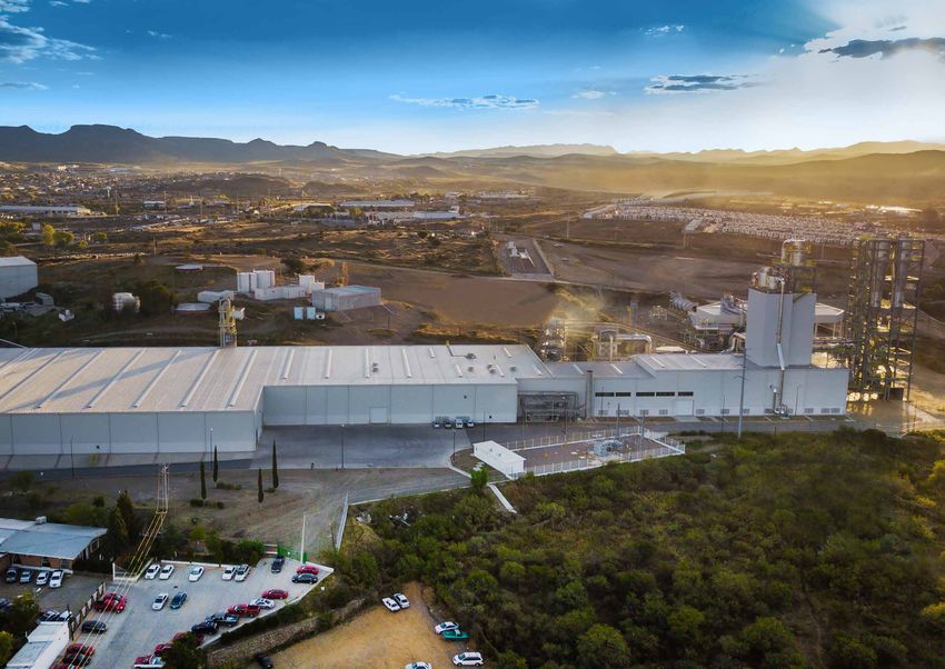
Close cooperation helps us move forward together. We are your strong and reliable
partner supporting you throughout the entire lifecycle of your plant. As a fifth-
generation family-owned company with more than 145 years of experience, we
have always proven continuity and commitment to our partners.

8                                                                                                   9
MOVE FORWARD - TOGETHER - Let's build your plant - Dieffenbacher
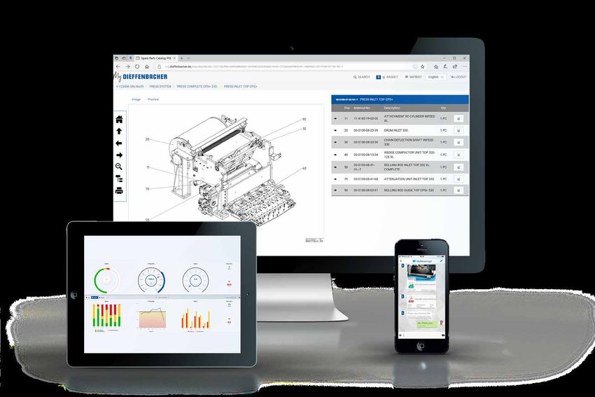
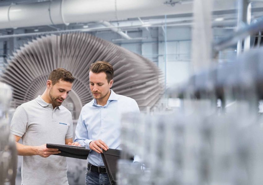
INCREASE                                     UPTIME CONTINUOUSLY

     Service that can do more

      To ensure that your plant runs trouble-­
      free for the long term, you need a part-
      ner who goes the extra mile for you.
      Not only are we there quickly if some-
      thing goes wrong, but we also look
      ahead together with you and optimize
     ­production efficiently.

     With ­individual service packages, digital
     support systems and regular training, we
     provide you with the tools you need to
     get the most out of your plant.

10                                                                      11
MOVE FORWARD - TOGETHER - Let's build your plant - Dieffenbacher
DIEFFENBACHER
LIFECYCLE SERVICES

MAXIMIZE UPTIME WITH PREVENTIVE SERVICES                                                                                             MINIMIZE DOWNTIME WITH REACTIVE SERVICES

                                             Process Optimization                                                                    MyMessenger                                    MyParts                                       MyCockpit
                                             A plant performance analysis is carried                                                 With your smartphone, use our                  Our digital spare parts catalog covers        MyCockpit provides you with
                                             out to evaluate the status of your plant.                                               ­easy-to-use messenger app to contact          spare parts identification and plant          available plant data on mobile
                                             Based on the results, production bottle-                                                 your team members and instantly               documentation. You can easily identi-         devices. Relevant people receive
                                             necks can be eliminated and the plant’s                                                  ­discuss your maintenance issues with         fy, select and request spare parts and        the information they need with
                                             productivity can be optimized.                                                            us. Every solved problem is documented,      view the corresponding documentation.         a quick glance.
Machine Inspections                                                                      Individual Spare Parts Packages               making it easier to resolve similar
and Performance Tracking                                                                 Our service specialists define individual     issues in the future.
Regular inspections are part of preventive                                               spare and wear parts packages for
maintenance. We help you analyze risks                                                   your plant. They take care of the
and weak points. We work on site to                                                      processing of all logistical matters,
help you identify optimization potential.                                                including issuing of all necessary
­Working remotely via our TEO tool, we                                                   export and import documents.
 are your optimization coach.
                                                                                                                                                  MyMessenger                                   MyParts                                MyCockpit

                                                                                                                                                                      Tele Engineering                         Express Delivery
                                                                                                                                                                       Online Service
                                                                                                                                                                            (TEO)

Training                                                                                 Inventory Management                                                    Tele Engineering Online                  Express Delivery
Through individual on-site trainings and                                                 We help you keep your inventory up                                      Service (TEO)                            A selection of critical and
annual trainings at our headquarters in                                                  to date. Spare parts condition checks                                   TEO is our online remote diagnostic      common spare parts is labeled
Eppingen, Germany, your staff gets deep                                                  and discontinuation controls are part                                   tool that provides 24 / 7 access and     as express parts. If we receive
knowledge about machine operation and                                                    of our inventory management offer,                                      support worldwide. Via TEO, our          your express parts order before
production processes, preventing mistakes                                                as is storage consulting.                                               ­Dieffenbacher experts can access        10 a.m., your delivery will be
in daily business.                                                                                                                                                all components of your plant for        shipped on the same day.
                                                                                                                                                                ­immediate troubleshooting.

12                                                                                                                                                                                                                                                                   13
MOVE FORWARD - TOGETHER - Let's build your plant - Dieffenbacher
DRIVE EFFICIENCY   FURTHER

                         Modernization solutions for
                        ­tomorrow

                        Modernizations are crucial to make
                        ­existing plants fit for the future. Our
                         solutions are tailored to your business.
                         We make your plant more efficient in
                         terms of consumption, processes and
                         productivity so that you can continuously
                         improve the profitability of your products.

14                                                                     15
MOVE FORWARD - TOGETHER - Let's build your plant - Dieffenbacher
HOW CAN WE HELP YOU
ACHIEVE MORE WITH YOUR PLANT?
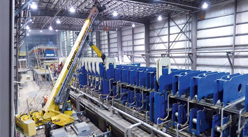
The economy is changing. Additional requirements, new guidelines and technical innovations make   NORBORD OSB PLANT RELOCATION
continuous modernization essential. Let us help you create a custom modernization concept for
your specific components, individual machines and complete plants. With Dieffenbacher you can
                                                                                                  FROM CANADA TO SCOTLAND
remain competitive.

COMPONENT EXCHANGE
Old or faulty components undermine your plant efficiency. Dieffenbacher quickly
replaces individual plant components with new ones adapted to your plant.

PLANT EXTENSION
The demands placed on wood-based panel plants are growing dynamically. A plant
extension helps you keep pace with the development and increase your capacity to
meet changing requirements. This can make your plant even more profitable.

PERFORMANCE OPTIMIZATION
Don’t overlook optimization potential during ongoing plant operation. We can develop
custom solution concepts for you, implement them and support you in monitoring their
success.

INTEGRATION AND NETWORKING
Industrial plants or entire production sites must increasingly be automated and
networked. We assist you in integrating our modernization solutions into your
existing processes and in automating existing plants. With Dieffenbacher you are
ready for tomorrow.

PLANT RELOCATION
Give your company added flexibility. We make plant relocations possible with
design, planning and timely implementation services. Benefit from our experience
with large-scale relocation projects.

CUSTOM CONVERSION PACKAGES
Planning extensive changes to your processes? Let us support your goals with                                                          Disassembly: Grand Prairie, Alberta, Canada
a needs analysis and custom conversion concepts.

                                                                                                  Installation: Inverness, Scotland

16                                                                                                                                                                            17
MOVE FORWARD - TOGETHER - Let's build your plant - Dieffenbacher
MAKE YOUR PRODUCTION   SMARTER

                       Digital solutions that simplify your
                       daily routine

                       Digitalization and automation make your
                       life easier. With permanent condition-­
                       monitoring, self-controlled production
                       solutions and the M­ yDieffenbacher
                       ­platform, you can make faster and safer
                        decisions, work efficiently and increase
                        the productivity of your plant.

18                                                                 19
THE FUTURE OF PANEL PLANTS—TODAY

                MyParts
                Our digital spare parts catalog covers spare parts
                identification and plant documentation. You can
                easily identify, select and request spare parts and
                view the corresponding documentation.

                                                                                                                                           MyMessenger
                                                                                                                                           With your smartphone, use our e­ asy-to-use
                                                                                                                                           ­messenger app to contact your team members
                                                                                                                                            and instantly ­discuss your maintenance issues
                                                                                                                                            with us. Every solved problem is documented,
                                                                                                                                            making it easier to resolve similar issues in
                                                                                                                                            the future.

                                                                      VARIOUS DIGITALIZATION SOLUTIONS ARE AVAILABLE
     MyCockpit
     MyCockpit provides you with available plant data                 Permanent condition-monitoring:                               Self-controlled production solutions:
     on mobile devices. Relevant people receive the
     information they need with a quick glance.                       ƒ    istance indicator counts the press’s total kilometers
                                                                          D                                                         ƒ   Intelligent forming line reaction in case of production
                                                                          achieved to date                                               interruptions, e.g., automatic stopping and controlled
                                                                      ƒ   Steel belt alignment index calculated from belt               restarting
                                                                           tracking behavior                                        ƒ    Automatically adjusted surface-layer ratio
                                                                      ƒ    Monitoring of control loop condition                    ƒ     Automated speed control based on material temperature
                                                                      ƒ     Gearbox temperature tracked over time                   ƒ      Automation of standard processes: press calibration,
                                                                      ƒ     Identification of the pressure insulation’s wear                emptying press after stop, etc.
                                                                      ƒ     Visualization of trends in chain elongation             ƒ       Automatic mat-moisture control
                                                                      ƒ     Etc.                                                    ƒ       Etc.

                                                                      Contact us for more information.

20                                                                                                                                                                                                 21
BUILD   BETTER                                      PRODUCTION LINES

             PB         MDF        OSB         LVL

             High-performance solutions for
             new plants and plant optimizations

             Browse through our portfolio on the
             following pages and build a profitable
             future with our broad range of products
             and solutions. Contact us whenever you
             need assistance. We are happy to support
             you in making the best decisions for your
             long-term success.

22                                                                          23
L O G YA R D                                                                                                                                                                                 CO N V E Y I N G , D E B A R K I N G

               Professional Solutions for OSB                                                                                             Wood Yard Technology
               Through the “OSB Logyard Alliance” with Holtec, Dieffenbacher completed its product range in the OSB                       Wood is a renewable resource and the basis for producing wood-based panels, cellulose and paper, pellets and
               ­area. Holtec, a well-known supplier of logyards, works closely with Dieffenbacher to design, manufacture                  numerous other products. Due to regional climate differences, raw material scarcity and increasing cost pres-
                and install logyards tailored to the customer’s OSB plant requirements. This includes the debarking, log                  sures, substitutes for classic round wood in the production of wood-based products are increasingly attractive.
                conditioning ­system, and OSB strander right through to the waste disposal system. Everything can be
               manu­factured and supplied from a single source.                                                                           Modern wood yards supplied by Dieffenbacher provide optimal plant flexibility. Depending on the application,
                                                                                                                                          functions such as debarking and cleaning can supplement loading, storage, dosing and conveying. Our
               For over 45 years, log processing has been a way of life for Holtec. Holtec has the knowledge and experience               proven drum chipper serves as the ideal first reduction stage for a variety of wood assortments. High-quality
               from designing, manufacturing and installing over 300 logyard systems.                                                     chips are the result. This intermediate bulk product can be used fully automatically and reliably for subse-
                                                                                                                                          quent processes in the production of PB, MDF and OSB boards, as well as pellets and cellulose products.

                                                                                                                                          Dieffenbacher reliably supports you from project planning to implementation and far beyond. We develop
                                                                                                                                          efficient, turnkey wood yard solutions that meet your requirements. Precise matching of individual compo-
                                                                                                                                          nents enables optimal performance of your plant, while robust machines designed for 24 / 7 work ensure
                                                                                                                                          maximum availability and low operating costs.

                    Logyards for                                                                                                            Wood Yards for                  Wood Yards for

                     OSB                                                                                                                      MDF                                  PB
                Log handling, waste,
                                                                                                                                          Handling of wood, waste, bark and fuel
                bark and fuel handling

                Debarking                                                                                                                 Debarking

                Conditioning

                Stranding                                                                                                                 Chipping

                                                                           OSB

24                                                                                                                            02 / 2020                                                                                                               25
W O O D YA R D T E C H N O L O G Y                                                                                                                                                                       CO N V E Y I N G , D E B A R K I N G

                                     SCC Storage Cross                                                                                                       DPC Dumping Pit
                             Chain Conveyor                                                                                                          Chain Scraper
Application                  „   Panel boards (PB, MDF, OSB)                                                                           Application   „   Panel boards (PB, MDF, OSB)
                             „   Biomass and renewable fuels                                                                                         „   Biomass and renewable fuels
                             „   Pellets and briquettes                                                                                              „   Pellets and briquettes
                             „   WPC / WFC                                                                                                           „   WPC / WFC
                             „   Pulp and paper                                                                                                      „   Pulp and paper

Description                  The SCC Storage Cross Chain Conveyor enables storing and conveying of round wood and slabs, loaded        Description   The DPC Dumping Pit Chain Scraper is designed for direct loading of wooden bulk materials. The material
                             by crane. The conveyor is executed with a closed bottom plate, integrated side wall and driven chains.                  is usually loaded by front loader or truck. The DPC acts as a buffer and equalizes bulk material flow with
                             Different singularizers can be mounted downstream from the SCC:                                                         an inclined section. Large heavy-duty horizontal feeding section and subsequent inclined trough with high
                             „ LS Log Singularizer separates logs by inclined installation and increased conveying speed.                            side walls and reinforced chains with carriers transport the dosed material to the subsequent conveyers.
                             „ SBS Slab Bundle Singularizer is executed as a movable table beneath the SCC. The bundles can easily
                                be opened in extended table position. The loose slabs are fed to the line by retracting the table.
                                                                                                                                       Customer      „   Designed for challenging conditions and heavy-duty loads during 24-hour continuous operation
                                                                                                                                       benefits      „   High storage volume, easy loading of even big volume of materials
 Customer                    „   High storage volume                                                                                                 „   Tailor-made solutions
­benefits                    „   Effective dosed conveying and singularizing of round wood and slabs                                                 „   Solid and reliable execution, low maintenance
                             „   Designed for challenging conditions and heavy-duty loads during 24-hour continuous operation                        „   Working speed freely adjustable by frequency converter
                             „   Solid and reliable execution, low maintenance
                             „   Working speed freely adjustable by frequency converter
                                                                                                                                       Technical     „   Heavy-duty endless chains with lateral guidance on both sides and reinforced carriers
                                                                                                                                       features      „   Integrated cleaning of chain and the carriers
Technical                    „   Number of chains can be adapted to material length                                                                  „   Plastic side guiding rails for reduced wear and friction of the chains
features                     „   Heavy-duty chains with reinforced carriers guided in U-shaped beams with integrated wear protection                 „   Discharge hopper and transition plate for easier material transmission to the following conveyor
                             „   Welded steel chains in North American design with high breaking load                                                „   Drives with torque overload monitoring
                             „   Driven via shaft-mounted gear motor, incl. torque support
                             „   Execution with right or left guiding wall available

                 Chipping,
                  Flaking,               Sorting,                               Forming,              Environmental
      Wood Yard, Stranding               Cleaning   Energy Systems,            Preheating              Technology
      Conveying,                                        Drying                               Press                      Handling,
      Debarking                                                       Gluing                Systems                     Finishing

26                                                                                                                                     02 / 2020                                                                                                                  27
W O O D YA R D T E C H N O L O G Y                                                                                                                                                                    CO N V E Y I N G , D E B A R K I N G

                           VFC Vibration                                                                                                                  VDT Vibration
                   Feeding Conveyor                                                                                                               Dosing Table
Application        „   Panel boards (PB, MDF, OSB)                                                                                  Application   „   Panel boards (PB, MDF, OSB)
                   „   Biomass and renewable fuels                                                                                                „   WPC / WFC
                   „   Pellets and briquettes                                                                                                     „   Pellets and briquettes
                   „   WPC / WFC                                                                                                                  „   Recycling
                   „   Pulp and paper                                                                                                             „   Biofuels

Description        The VFC Vibration Feeding Conveyor is designed for continuous dosed conveying of different bulk materials.       Description   The VDT Vibration Dosing Table is designed for challenging conditions at the wood yard. The material
                   The material is usually loaded by front loader, crane or prefeeder. The VFC is used for transport of different                 is usually loaded by front loader or truck. The VDT acts as a buffer and equalizes bulk material flow.
                   kinds of materials to the subsequent feeders or directly into the machine.                                                     The material is further transported to the subsequent feeders.

 Customer          „   Designed for challenging conditions and heavy-duty loads                                                     Customer      „   Designed for challenging conditions and heavy-duty loads
­benefits          „   Solid and reliable execution                                                                                 benefits      „   Solid and reliable execution
                   „   Resonance drive for low energy consumption                                                                                 „   Resonance drive for low energy consumption
                   „   Low maintenance and service-friendly                                                                                       „   Low maintenance and service-friendly

Technical          „   High conveying volume possible                                                                               Technical     „   High capacities available
features           „   Heavy-duty welded trough with reinforced bottom plate                                                        features      „   Heavy-duty welded trough
                   „   Resonance drive supported by solid springs and stabilizers                                                                 „   Resonance drive supported by solid springs and stabilizers
                   „   Execution with feeding hopper, screening zone, metal detector or other required features possible                          „   Heavy-duty bottom plate

      Wood Yard,
      Conveying,
      Debarking

28                                                                                                                                  02 / 2020                                                                                                              29
W O O D YA R D T E C H N O L O G Y                                                                                                                                                                  CO N V E Y I N G , D E B A R K I N G

                                               FBC Feeding Belt Conveyor                                                                                                    SPC Steel Plate Conveyor
Application        „   Panel boards (PB, MDF, OSB)                                                                                Application   „   Panel boards (PB, MDF, OSB)
                   „   Biomass and renewable fuels                                                                                              „   Biomass and renewable fuels
                   „   Pellets and briquettes                                                                                                   „   Pellets and briquettes
                   „   WPC / WFC                                                                                                                „   WPC / WFC
                   „   Pulp and paper                                                                                                           „   Pulp and paper

Description        The FBC Feeding Belt Conveyor is designed for continuous transport of logs and other wooden materials          Description   The SPC Steel Plate Conveyor is designed for continuous transport of heavyweight logs and other
                   to the subsequent conveyor or directly into the machine. The material is usually loaded by grapple, upstream                 wooden materials to the downstream conveyor or directly into the machine. The material is usually
                   longitudinal or cross feeders. The conveyor is executed as a welded trough with heavy-duty feeding belt.                     loaded by grapple, upstream longitudinal or cross feeders. The conveyor is executed with welded
                                                                                                                                                trough and driven chains with specially formed reinforced steel plates.

 Customer          „   Solid and reliable execution, designed for challenging conditions and heavy loads                          Customer      „   Solid and reliable execution, designed for challenging conditions and especially heavy-duty loads
­benefits          „   Tailor-made solutions                                                                                      benefits      „   Tailor-made solutions
                   „   Low maintenance and service friendly                                                                                     „   Low maintenance and service friendly
                   „   High transport volume                                                                                                    „   High transport volume
                   „   Feeding hopper for easy material loading                                                                                 „   Feeding hopper for easy loading

Technical          „   Heavy-duty welded trough with reinforced supporting frame                                                  Technical     „   Heavy-duty welded trough with reinforced supporting frame
features           „   Execution with integrable wooden trough for metal detector; removal zone                                   features      „   Heavy, special shaped wear-resistant steel plates with extra high section modulus,
                       with swiveling walls or doors for metal-contaminated logs or cleaning zone is possible                                       screwed for easy disassembly
                   „   Roller sections consist of roller rows mounted on damping elements                                                       „   Steel plates glide on damped longitudinal beams, therefore the reinforced chains
                   „   Reinforced damped plates in the feeding areas                                                                                are only loaded by tension forces
                   „   Reverse operation                                                                                                        „   Steel plates glide on plastic slide rails to minimize friction and noise
                                                                                                                                                „   Reverse operation possible

      Wood Yard,
      Conveying,
      Debarking

30                                                                                                                                02 / 2020                                                                                                             31
W O O D YA R D T E C H N O L O G Y                                                                                                                                                               CO N V E Y I N G , D E B A R K I N G

                                               CBC Chain Bed Conveyor                                                                                                   RS Cleaning Zone
Application        „   Panel boards (PB, MDF, OSB)                                                                           Application   „   Panel boards (PB, MDF, OSB)
                   „   Biomass and renewable fuels                                                                                         „   Biomass and renewable fuels
                   „   Pellets and briquettes                                                                                              „   Pellets and briquettes
                   „   WPC / WFC                                                                                                           „   WPC / WFC
                   „   Pulp and paper                                                                                                      „   Pulp and paper

Description        The CBC Chain Bed Conveyor is designed for continuous transport of heavyweight wooden logs to the         Description   The RS Cleaning Zone is designed for separating loose bark and other impurities from the conveying
                   subsequent conveyor. The material is usually loaded by grapple, upstream longitudinal or cross feeders.                 material. Depending on the application, the RS is executed with various numbers and forms of discs
                   The conveyor is executed as a welded trough with driven parallel-running reinforced chains.                             or rollers and can be integrated into different kind of horizontal conveyor systems.

 Customer          „   Solid and reliable execution for high uptime                                                          Customer      „   Effective cleaning of impurities and challenging contaminations
­benefits          „   Designed for challenging conditions and heavy-duty loads                                              benefits      „   Designed for difficult conditions and heavy-duty loads
                   „   High transport volume                                                                                               „   Robust and reliable execution
                   „   Tailor-made solutions                                                                                               „   Modular solution, easy integrable
                   „   Low maintenance and service friendly
                   „   Feeding hopper for easy loading (optional)
                                                                                                                             Technical     „   Different shapes of discs (elliptic / star, etc.) and rollers
                                                                                                                             features      „   Reinforced chains between the disc shafts
Technical          „   Heavy-duty welded trough                                                                                            „   Chain tensioning device with polymeric wear plates
features           „   Integrated or separate log feeding section executed as a reinforced steel hopper available                          „   Single or multiple drives, different shaft rotation speed possible
                   „   U-shaped guiding beams with integrated wear protection                                                              „   Reverse operation possible
                   „   Special welded steel chains in North American design with high breaking load
                   „   Reverse operation (optional)

      Wood Yard,
      Conveying,
      Debarking

32                                                                                                                           02 / 2020                                                                                                          33
DEBARKING                                                                                                                                                                                                        CO N V E Y I N G , D E B A R K I N G

                                                                                                                MRE Rotor Debarker

                                                                                                                 Type          Number of      Number of Rotor        Rotor       Number of   Drive     Drive     Drive     Drive       Drives     Capacity2   Dimensions3
                                                                                                                               sections       rotors per length      diameter    debarking   hydraulic auxilary  discharge heating     cooler +   approx.
                                                                                                                                              section                with        cams per    unit      functions roller                cooler
                                                                                                                                                                     cams1       rotor                                                 pump
                                                                                                                               pcs.           pcs.         m         mm          pcs.        kW        kW          kW        kW        kW         t/h b.d.    m (L × W × H)

                                                                                                                 MRE 800-1            1              2         12      950         180        2 × 45        22       7.5     4 × 1.4    3+4       25 – 35     16.4 × 3.3 × 5.3

                                                                                                                 MRE 800-2            2              2           9     950         135        4 × 45        22       7.5     4 × 1.4    3+4       40 – 50     23.4 × 3.3 × 5.3

                                                                                                                 MRE 800-3            2              2         12      950         180        4 × 45        22       7.5     4 × 1.4    3+4       60 – 70     29.4 × 3.3 × 5.3

                                                                                                                 1) Rotor body diameter for all machine types—820 mm
                                                                                                                 2) Depending on infeed material and required debarking result
                                                                                                                 3) Dimensions of basic machine; height without sub-frame.

                                                MRE Rotor Debarker
Application        „   OSB boards
                   „   Panel boards (PB, MDF)
                   „   Pellets and briquettes
                   „   Pulp and paper

                                                                                                                                                            HH
Description        The MRE Rotor Debarker offers the efficient continuous debarking of round wood.
                   The logs are laterally fed into the trough, set into rotating motion by long rotors
                   with debarking tools and moved to the discharge area by the tilt of the rotors.                                                                                                                      LL

 Customer          „   Highly efficient debarking due to interaction between rotation, friction and sur-
­benefits              face moistening of logs
                   „   Constant high capacity: up to 70 t/h b.d.
                   „   Precise control of debarking process and processing quantities
                   „   Fully automatic operation
                                                                                                                                      W
                       High machine availability
                                                                                                                                      W
                   „

Technical          „   Hydraulically adjustable, stepless closing gate for the control of processing material
features               quantities and regulation of the debarking quality
                   „   Two or four one-piece rotors, according to machine size
                   „   Speed of each rotor variable and individually adjustable
                   „   The debarking tools (cams) are screwed and individually exchangeable
                   „   Water spray system for the reduction and suppression of dust, as well as cleaning
                       and moistening the logs for better sliding
                   „   Central hydraulic unit for all drives and functions of the debarker

      Wood Yard,
      Conveying,
      Debarking

34                                                                                                              02 / 2020                                                                                                                                                     35
STRANDING                                                                                                                                                                                                   CH I P P I N G, F L A K I N G, S T R A N D I N G

                             SmartRING Stranders                                                                                               SmartRING Stranders

                                                                                                                                                Type                                     28 / 81 SmartRING Stranders          32 / 88 SmartRING Stranders

                             Dieffenbacher and Kadant Carmanah Design signed a cooperation agreement in 2013 for the supply of disc             Number of knives                         44                                   48
                             and ring stranding systems for engineered wood applications outside of North America.                              Ring assembly weight, approx.   t        7.3                                  8.5
                                                                                                                                                Ring                            rpm      370                                  334
                             The strander division of Kadant (formerly Carmanah), which celebrated its 100th year in business in 2013,
                             is outstanding in the supply of disc and ring stranders to the engineered wood industry with installations         Ring and arbor work             t / m²   13.2                                 17.5
                             in North and South America, Europe, the UK-, and New Zealand.
                                                                                                                                                Motor size                      kW       900 / 1,100 (pine / hardwoods)       1,100 / 1,350 (pine / hardwoods)

Application                  Production of flakes / strands for the production of engineered wood products including OSB, OSL, etc.             Drive type                               Power bands V-belts                  Power bands V-belts
                                                                                                                                                Total weight, approx.           t        54                                   60

Description                  The SmartRING Strander produces high-quality and consistent strands and is designed for easy adjustment            Dimensions (L × W × H)          mm       9,235 × 4,830 × 5,505                9,500 × 4,935 × 5,540
                             of strand parameters. Maintenance is straightforward, and wear components are easily replaced to ensure            Traverse way (S)                mm       1,665                                1,805
                             downtime is minimized. Additionally, several features in the SmartRING platform, monitor knife installation
                             and sub­sequently identify i­ssues and, if necessary, act to minimize the ­potential of serious m
                                                                                                                             ­ achine damage
                             or catastrophic failure.

 Customer                    „   Consistent strand quality through real-time adjustment to forward ring velocity
­benefits                    „   Wear components quickly and easily replaced as required
                             „   Knife change procedure automated through nutrunner system
                             „   Option to utilize disposable knives
                             „   Safety features minimize the potential of serious machine failure

Technical                    „   Real-time ring RPM monitor to adjust forward ring velocity during cutting cycle
­features                    „   Automated nutrunner system ensures knives adequately clamped prior to operating
                             „   Replaceable knife holding and clamping components eliminate the need for ring grinding
                                 allowing for more consistent cutting geometry and fewer fines produced over the ring’s life
                             „   Ring design to allow complete replacement in 10-hour period
                             „   Designed to accommodate plate or disposable knives

                 Chipping,
                  Flaking,               Sorting,                                Forming,               Environmental
      Wood Yard, Stranding               Cleaning    Energy Systems,            Preheating               Technology
      Conveying,                                         Drying                               Press                          Handling,
      Debarking                                                        Gluing                Systems                         Finishing

36                                                                                                                                             02 / 2020                                                                                                         37
CH I P P I N G                                                                                                                                                                             CH I P P I N G, F L A K I N G, S T R A N D I N G

                                                                                                              HRL Drum Chipper

                                                                                                               Type1                              Main drive             Infeed roller drive Capacity2) Capacity2) Chip Vol.3)                          Dimensions4)          Weight4)
                                                                                                               Rotor / Infeed opening                                    (upper / lower)                                                                                      approx.
                                                                                                               mm Ø / H1 × W1                     kW                     kW                  rm / h     t / h b.d. m3 / h                               m (L × W × H)         t

                                                                                                               HRL 450 / 150 x 500                30 – 45                2.2 / 2.2                 20 – 24          6–7             40 – 47             1.6 × 2.2 × 1.2            1.9
                                                                                                               HRL 600 / 200 x 650                55 – 75                3/3                       34 – 40          10 – 12         67 – 80             1.6 × 2.4 × 1.3            5.5
                                                                                                               HRL 800 / 250 x 650                75 – 110               5.5 / 5.5                 44 – 50          13 – 15         87 – 100            2.4 × 1.7 × 1.4            7.5
                                                                                                               			x 800                           90 – 132               5.5 / 5.5                 54 – 64          16 – 19         107 – 127           2.4 × 1.8 × 1.4            8.3
                                                                                                               HRL 1000 / 350 x 800               110 – 160              7.5 / 7.5                 74 – 87          22 – 26         147 – 173           2.8 × 2.1 × 1.7             11
                                                                                                               			x 1000                          132 – 200              7.5 / 7.5                 94 – 110         28 – 33         187 – 220           2.8 × 2.3 × 1.7            13
                                                                                                               HRL 1200 / 450 x 800               200 – 315              11 / 11                   97 – 114         29 – 34         193 – 227           3.5 × 2.5 × 1.9            14
                                                                                                               			x 1000                          250 – 355              11 / 11                   117 – 140        35 – 42         233 – 280           3.5 × 2.7 × 1.9           15.5
                                                                                                               			x 1200                          250 – 355              11 / 11                   144 –170         43 – 51         287 – 340           3.5 × 2.9 × 1.9            17

                                                      HRL Drum Chipper                                         HRL 1400 / 550 x 1000
                                                                                                               			x 1200
                                                                                                                                                  315 – 500
                                                                                                                                                  355 – 500
                                                                                                                                                                         15 / 15
                                                                                                                                                                         15 / 15
                                                                                                                                                                                                   144 –170
                                                                                                                                                                                                   177 – 210
                                                                                                                                                                                                                    43 – 51
                                                                                                                                                                                                                    53 – 63
                                                                                                                                                                                                                                    287– 340
                                                                                                                                                                                                                                    354 – 420
                                                                                                                                                                                                                                                        4.2 × 2.6 × 2.1
                                                                                                                                                                                                                                                        4.2 × 2.8 × 2.1
                                                                                                                                                                                                                                                                                   22
                                                                                                                                                                                                                                                                                   24
                                                                                                               			x 1500                          400 – 630              15 / 15                   220 – 260        66 – 78         440 – 520           4.2 × 3.1 × 2.1            26
Application               „   Panel boards (PB, MDF, OSB)                                                      HRL 1600 / 600 x 1000              400 – 500              18.5 / 18.5               157 – 187        47 – 56         313 – 373           4.4 × 2.7 × 2.1            30
                          „   Biomass and renewable fuels
                                                                                                               			x 1200                          500 – 630              18.5 / 18.5               193 – 227        58 – 68         386 – 453           4.4 × 2.9 × 2.4            33
                          „   WPC / WFC
                          „   Pulp and paper                                                                   			x 1500                          500 – 800              18.5 / 18.5               240 – 284        72 – 85         480 – 567           4.4 × 3.2 × 2.4            37
                                                                                                               HRL 1800 / 750 x 1000              630 – 800              18.5 / 18.5               200 – 234        60 – 70         400 – 467           5.1 × 2.9 × 2.5            34
                                                                                                               			x 1200                          630 – 800              18.5 / 18.5               240 – 287        72 – 86         480 – 573           5.1 × 3.0 × 2.5            37
Description               The HRL Drum Chipper is a tried-and-trusted solution for the production of
                          high-quality chips from different wood assortments. The material is gripped          			x 1500                          630 – 1,000            18.5 / 18.5               300 – 354        90 – 106        600 – 707           5.1 × 3.3 × 2.5            40
                          horizontally by specially toothed infeed rollers and continuously fed to the         HRL 2000 / 850 x 1200              800 – 1,250            22 / 22                   274 – 324        82 – 97         547– 647            5.7 × 3.4 × 2.7            60
                          ­chipping rotor. The knives of the rotor cut the material to the required chip       			x 1500                          800 – 1,400            22 / 22                   340 – 400        102 – 120       680 – 800           5.7 × 3.7 × 2.7            66
                           length. The chipped material passes an individually adapted refractioning grid.
                                                                                                               			x 1700                          800 – 1,400            22 / 22                   384 – 454        115 – 136       767 – 907           5.7 × 3.9 × 2.7            72
                                                                                                               HRL 2400 / 1000 x 1500             1,000 – 1,600          22 / 22                   400 – 474        120 – 142       800 – 947           6.8 × 3.9 × 3.0            83
 Customer                 „   Free choice of wood assortment: round wood, log ends, slabs and offcuts,         			x 1700                          1,000 – 1,600          22 / 22                   450 – 534        135 – 160       900 –1,067          6.8 × 4.0 × 3.0            91
­benefits                     veneer residues or waste wood
                                                                                                               1) Individual machine sizes and motor power upon request    2) Referring to round wood with a density of 450 kg/m3 b.d., a 11 – 13 % filling ratio of the infeed, and a chip
                          „   Constant high chip quality; chip length of 4 – 180 mm possible
                                                                                                               length of 40 mm    3) Chip volume flow based on a bulk weight of 150 kg/m3    4) Dimensions and weight of basic machine without main motor
                          „   Special machine solutions for production of maxi-chips, micro-chips and
                              biomass such as HRL-OSB, HRL-M, HRL-B
                          „   Robust, long-term reliable, low operating costs due to simplified maintenance
                          „   Energy-efficient size reduction
                          „   Essential parts of the machine wear-protected and exchangeable

Technical                 „   Aggressively shaped infeed rollers with narrow running gaps
­features                 „   Chipping rotor with slewable knife clamping plates for quick and
                              easy knife exchange
                          „   Regrindable wear plates under the chipping knives
                          „   Counter knife screw-fastened, regrindable, once turnable
                          „   Wear-resistant refractioning grid individually perforated

              Chipping,
               Flaking,
              Stranding

38                                                                                                            02 / 2020                                                                                                                                                                   39
CH I P P I N G                                                                                                                                                                                CH I P P I N G, F L A K I N G, S T R A N D I N G

                                                                                                                     SMV Cutting Rotor / Rechipper

                                                                                                                         Type                                   Main drive                     Capa­city1            Dimensions2       Weight2
                                                                                                                         Rotor / Infeed opening                                                                                        approx.
                                                                                                                         mm Ø / L1 × W1                         kW                             t/h b.d.              m (L × W × H)     t

                                                                                                                         SMV 450 / 200 × 650                    22 – 55                        1–4                   0.8 × 1.0 × 1.1   1.9
                                                                                                                         SMV 600 / 300 × 650                    45 – 90                        2–6                   1.1 × 1.0 × 1.4   2.6
                                                                                                                         SMV 800 / 350 × 800                    55 – 132                       4–8                   1.5 × 1.2 × 1.9   4.2
                                                                                                                         SMV 1000 / 400 × 1000                  90 – 200                       6 – 13                1.8 × 1.4 × 2.2   6.3
                                                                                                                         1) Depending on input and size of output material
                                                                                                                         2) Dimensions and weight of basic machine without main motor and infeed hopper

                                  SMV Cutting Rotor /                                                                                       W1                                                              L1

                          Rechipper
Application               „   Combustion (energy from waste)
                          „   Recycling
                          „   Panel boards (PB, MDF, OSB)

Description               The SMV Cutting Rotor is an effective robust solution for the reduction of short-
                          sized industrial waste wood, bark and fibrous raw materials into quality chips.
                          The material is fed through the large vertical hopper, chipped by the knives of
                          the rotor and further classified by an individually adapted refractioning grid.

                                                                                                                     H
 Customer                 „   Wide range of input material such as screened chip oversizes, short-sized industrial
­benefits                     waste wood, bark, annual plants, cardboard waste and fibrous raw materials
                          „   Output material size adjustable
                          „   Energy-efficient size reduction
                          „   Essential parts of the machine wear-protected and exchangeable
                          „   Low-maintenance and service-friendly                                                                             W                                                                 L

Technical                 „   Large vertical infeed hopper
­features                 „   Chipping rotor in heavy-duty execution with wear protection
                          „   Counter knife of high-quality special steel, regrindable and adjustable
                          „   Narrow gap between the rotor and counter-knife, precise adjustable
                          „   Easy access to the rotor for maintenance

              Chipping,
               Flaking,
              Stranding

40                                                                                                                   02 / 2020                                                                                                                   41
CRUSH I N G                                                                                                                                                                                CH I P P I N G, F L A K I N G, S T R A N D I N G

                                                                                                                       MGB Big Crusher

                                                                                                                        Type1                     Rotor2         Rotor           Main      Capacity3    Hopper    Hopper           Machine          Weight
                                                                                                                        Power / Length                           speed           drive                  ­volume   cross section   ­dimensions4      approx.4
                                                                                                                        kW / mm L1                mm Ø           rpm             kW        t/h b.d.      m3       m (L1 × W1)      m (L × W × H)    t

                                                                                                                        MGB 32 / 3000                 815             24             132      15 – 20      15       3.0 × 2.8     4.8 × 3.3 × 3.3      30
                                                                                                                        MGB 132 / 4000              1,025             24             132     20 – 25       20       4.0 × 2.8     5.8 × 3.3 × 3.3      35
                                                                                                                        MGB 160 / 4000              1,025             24             160     25 – 35       20       4.0 × 2.8     5.8 × 3.3 × 3.3      35
                                                                                                                        MGB 200 / 4000              1,025             21             200     35 – 40       20       4.0 × 2.8     5.8 × 3.3 × 3.3      35
                                                                                                                        MGB 200 / 5000              1,025             21             200     40 – 50       25       5.0 × 2.8     6.8 × 3.6 × 3.3      40
                                                                                                                        1) Individual machine sizes and motor power upon request
                                                                                                                        2) Varying depending on number and type of teeth
                                                                                                                        3) Depending on input and size of output material
                                                                                                                        4) Dimensions of basic machine with main motor and infeed hopper

                                                      MGB Big Crusher
Application               „   Panel boards (PB, MDF, OSB)
                          „   Recycling
                          „   Biomass and renewable fuels
                          „   Combustion (energy from waste)

Description               The MAIER MGB Big Crusher is the ideal solution for the reduction of large-volume
                          and bulky wooden material or other brittle residues.
                          Material is directly fed through the large infeed hopper, crushed between a
                          slow rotating, large, toothed roller and aggressive crushing bars
                          at the bottom of the crushing chamber.

 Customer                 „   Wide range of input material, from waste wood, railway ties, pallets and furniture
­benefits                     to root stumps and electronic waste
                          „   Output material: 100 – 500 mm, adjustable
                          „   Insensitive against impurities and contaminations
                          „   Robust, long-term reliable, low energy consumption and operating costs
                          „   Easy overfloor installation

Technical                 „   Large-volumed infeed hopper; available with hydraulically swiveling side wall
­features                 „   Single-shaft-principle; power transmission to the crusher roller by electro-mechanical
                              power train with hydro clutch
                          „   Wear-protected crushing teeth at the crusher roller, individually shaped,
                              can be re-armored when worn
                          „   Easily exchangeable crushing bars with aggressive edges
                          „   Discharge grate, segmented, in manually movable or hydraulically supported execution

              Chipping,
               Flaking,
              Stranding

42                                                                                                                     02 / 2020                                                                                                                               43
HAMMER MILLING                                                                                                                                                                                         CH I P P I N G, F L A K I N G, S T R A N D I N G

                                                                                                                                SRH Beating Rotor

                                                                                                                                 Type                               Main drive             Infeed roller drive    Capa­city1   Dimensions2       Weight2
                                                                                                                                 Rotor / Infeed opening                                    (upper / lower)                                       approx.
                                                                                                                                 mm Ø / H1 × W1                     kW                     kW                     t/h b.d.     m (L × W × H)     t

                                                                                                                                 SRH 600 / 200 × 1000               75 – 110               2.2 / 2.2               3–5         1.6 × 1.4 × 1.1   5
                                                                                                                                 SRH 1000 / 350 × 1000              110 – 160              5.5 / 7.5               5 – 10      2.6 × 1.4 × 1.7   10
                                                                                                                                 SRH 1200 / 350 × 1300              250 – 315              5.5 / 7.5              10 – 35      3.5 × 1.7 × 1.8   16
                                                                                                                                 SRH 1600 / 600 × 1500              315 – 450              9.2 / 11               30 – 55      4.8 × 3.1 × 2.6   28
                                                                                                                                 1) Depending on input and size of output material
                                                                                                                                 2) Dimensions and weight of complete machine without main motor

                                                      SRH Beating Rotor
Application               „   Combustion (energy from waste)
                          „   Recycling
                          „   Panel boards (PB, MDF, OSB)

Description               The SRH Beating Rotor is a reliable machine for the production of chips from recycled materials
                          and brittle residues.

                          The material is gripped horizontally by special toothed infeed rollers and rushed with high kinetic
                          energy between the fast rotating heavy beaters and the counter knife. The crushed material is
                          further homogenized to the required size at the refractioning grid.

Customer                  „   Wide range of input material, from industrial waste wood, pallets, reclaimed
benefits                      timber to saw mill residues and presorted recyclables
                          „   Output material size individually adjustable
                          „   Energy-efficient size reduction
                          „   Insensitive to impurities
                          „   Essential parts of the machine wear-protected and easily exchangeable

Technical                 „   Aggressively shaped infeed rollers with narrow running gaps
features                  „   Pendulum mounted heavy beaters, individually adapted, once turnable (see detail photo above)
                          „   Rotor beaters and beater axes mounted in bushings
                          „   Counter knife screw-fastened, regrindable, once turnable
                          „   Wear-resistant refractioning grid, perforation individually adapted

              Chipping,
               Flaking,
              Stranding

44                                                                                                                              02 / 2020                                                                                                                  45
HAMMER MILLING                                                                                                                                                                       CH I P P I N G, F L A K I N G, S T R A N D I N G

                                                                                                             SRV Beating Rotor

                                                                                                              Type                                     Main drive                     Capa­city1     Dimensions2       Weight2
                                                                                                              Rotor / Infeed opening                                                                                   approx.
                                                                                                              mm Ø / L1 × W1                           kW                             t/h b.d.       m (L × W × H)     t

                                                                                                              SRV 600 / 300 x 650                      75 – 110                       1–3            1.1 × 1.5 × 1.0    2.3
                                                                                                              SRV 800 / 300 x 700                      75 – 132                       3–6            1.7 × 1.3 × 1.2    4.5
                                                                                                              SRV 1000 / 700 x 1200                    110 – 160                      6 – 10         2.6 × 2.6 × 1.6    8.0
                                                                                                              SRV 1200 / 850 x 1500                    160 – 250                      10 – 15        2.7 × 3.1 × 1.8   12.0
                                                                                                              SRV 1200 / 850 x 2000                    250 – 315                      15 – 25        2.7 × 3.6 × 1.8   16.0
                                                                                                              SRV 1600 / 850 x 2000                    400 – 630                      25 – 40        3.2 × 3.6 × 2.4   20.0
                                                                                                              1) Depending on input and size of output material
                                                                                                              2) Dimensions and weight of basic machine without main motor and infeed hopper

                                                      SRV Beating Rotor
Application               „   Combustion (energy from waste)
                          „   Recycling
                          „   Panel boards (PB, MDF, OSB)

Description               The SRV Beating Rotor is a cost-effective solution for the production of chips
                          from pre-crushed recycling materials and brittle residues.
                          The material is fed through the large vertical hopper, crushed with high kinetic
                          energy between the fast rotating heavy rotor beaters and the impact plate.
                          The crushed material is further homogenized to the required size by the ­
                          re­fractioning grid.

Customer                  „   Wide range of input material, from industrial waste wood, pallets, reclaimed
benefits                      timber to saw mill residues and presorted recyclables
                          „   Output material size adjustable
                          „   Energy-efficient size reduction
                          „   Insensitive to impurities
                          „   Essential parts of the machine wear-protected and exchangeable

Technical                 „   Large vertical infeed hopper
features                  „   Pendulum-mounted heavy rotor hammers, individually adapted, once turnable
                          „   Rotor beaters and beater axes mounted in bushings
                          „   Exchangeable impact plate of wear-resistant special steel
                          „   Wear-resistant refractioning grid, perforation individually adapted

              Chipping,
               Flaking,
              Stranding

46                                                                                                           02 / 2020                                                                                                             47
I M PA C T M I L L I N G                                                                                                                                                                                 CH I P P I N G, F L A K I N G, S T R A N D I N G

                                                                                                                              ClassiSizer—Dust Preparation

                                                                                                                               Type                 Capacity1            Rotor beating Number of im-                  Installed             Number of            Dimensions2       Weight3
                                                                                                                                                    approx.              diameter      pact elements                  power1                screens                                approx.
                                                                                                                                                    t/h b.d.             mm            pcs.                           kW                    pcs.                 m (L × W × H)     t

                                                                                                                               CS 1200              1 – 1.5                    1,100                   10                 132 – 250                12            3.0 × 5.5 × 4.1       14
                                                                                                                               CS 1600              2 – 3.5                    1,500                   10                250 – 355                 16            3.7 × 6.2 × 4.9       28
                                                                                                                               CS 2000              3 – 5.0                    1,860                   12                355 – 630                 14            4.1 × 6.6 × 5.2      36
                                                                                                                               1) Maximum values achieved when processing dry material (e.g., micro-chips, flakes, pre-crushed board residues) using 1.8 mm screens.
                                                                                                                                  Various screen perforations possible. Capacity depends on input and size of output material.
                                                                                                                               2) Dimensions of basic machine include screw conveyor without infeed chute and steelwork
                                                                                                                               3) Weight without motor and steelwork

                                                      ClassiSizer
Application               „   Particleboards
                          „   Pellets and briquettes
                          „   Biomass and renewable fuels (e.g., substrates for biogas production)
                          „   Dust for combustion (energy and heat generation)
                          „   WPC / WFC
                          „   Recycling (wood and non-wood)
                          „   Refuse-derived fuel (RDF)

Description               The ClassiSizer reduces input materials to the desired particle size in one step. The material is
                          fed from above into the impact chamber where it is resized with high kinetic energy by the fast
                          rotating rotor and interaction of the particles. The final calibration of material is realized by
                          screens, perforated according to the application. The endproduct is collected in two discharge
                          boxes and fed out by screws.

Customer                  „   Input material ranging from small wooden particles to offcuts
benefits                  „   Feeding of inhomogeneous material mix possible
                          „   Variable particle size and geometry of final material due to use of screens
                              with different mesh sizes
                          „   Energy-efficient size reduction due to impact technology (high kinetic energy)
                          „   Easy maintenance due to direct access to the impact chamber
                          „   Essential parts of the machine wear protected and easy exchangeable

Technical                 „   Polygonal design of the impact chamber with wear-resistant flat screens for optimal
features                      impact effect, easy exchange of individual screen segments
                          „   Rotor with impact elements; different adjusting angle and shape of impact elements
                              depending on application
                          „   Different drive concepts (direct drive, drive via gear box), according to the application
                          „   Fulfillment of ATEX requirements due to different safety concepts (Q-boxes or explosion vans)
                          „   Stand-alone unit; on-floor installation

              Chipping,
               Flaking,
              Stranding

48                                                                                                                            02 / 2020                                                                                                                                                      49
HAMMER MILLING                                                                                                                                                                                       CH I P P I N G, F L A K I N G, S T R A N D I N G

                                                                                                                           MSZ Beating Flaker

                                                                                                                              Type                               Main drive                Capa­city1         Dimensions        Dimensions         Weight2
                                                                                                                              Rotor / Working width                                                          ­basic machine2   c­ omplete system   approx.
                                                                                                                              mm Ø / W1                          kW                        t/h b.d.           m (L × W × H)    m (A × B × C)       t

                                                                                                                              MSZ 800 / 600                      75 – 110                  1 – 2.5           2.0 × 1.8 × 1.8   2.9 × 2.2 × 4.1      3.5
                                                                                                                              MSZ 1000 / 1200                    110 – 200                 3–6               2.5 × 2.0 × 1.8   3.0 × 2.9 × 4.3      5.0
                                                                                                                              MSZ 1200 / 1600                    200 – 315                 5–9               2.7 × 2.5 × 2.0   3.1 × 4.2 × 4.6      8.0
                                                                                                                              MSZ 1200 / 2000                    250 – 400                 7 – 12            3.1 × 2.5 × 2.0   3.1 × 4.6 × 4.6     10.0
                                                                                                                              MSZ 1600 / 2000                    355 – 500                 10 – 18           3.1 × 2.8 × 2.4   3.1 × 4.8 × 4.9     15.0
                                                                                                                              1) Depending on input and size of output material
                                                                                                                              2) Dimensions and weight of basic machine without add-on units

                                                      MSZ Beating Flaker
Application               „   Particleboards
                          „   Recycling
                          „   Pellets and briquettes
                          „   Cement-bonded particleboards
                          „   Pulp and paper
                          „   Animal bedding
                          „   Combustion (energy from waste)

Description               The MSZ Beating Flaker is a tried-and-trusted heavy-duty machine for effective ­processing of
                          dry and wet wooden chips, shavings, pellets and renewable ­materials into slim quality flakes.
                          After passing the VC Vibration Conveyor, the permanent magnet drum and the HPS Heavy Particle
                          Separator, the material is milled and classified b
                                                                           ­ etween the beaters of the
                          fast rotating rotor and the alternately arranged ­grinding tracks and screens.

Customer                  „   Adjustable fineness of final product, narrow particle size distribution
benefits                  „   Robust machine design, insensitive to impurities
                          „   Easy and quick exchange of grinding tracks, screens and beaters
                          „   Low wear and maintenance costs due to reverse operation; service-friendly
                          „   High machine availability

Technical                 „   Individually adapted screens and grinding tracks
features                  „   Pendulum mounted highly wear-resistant beaters that swivel in case of overload
                              (machine protection)
                          „   Easy exchange of rotor beaters and beater axes due to quick-change system
                          „   Grinding tracks in divided execution; middle and lower grinding tracks laterally movable
                          „   Optional hydraulic system for easier maintenance of screens and grinding tracks

              Chipping,
               Flaking,
              Stranding

50                                                                                                                         02 / 2020                                                                                                                         51
New design
FL AKING

                                                                                                                                                    FlowOptimizer

                       MRZ / MRZ HS                                                                                 FlowOptimizer—developed to improve material feeding                                                           Optimum material distribution over the total installed knife length

              Knife Ring Flaker                                                                                     The uneven material distribution in the flaking chamber is a well-known problem of the state-of-the-
                                                                                                                    art knife ring flaker systems in the market. As a result, the total installed knife length cannot always be
                                                                                                                    used evenly, causing uneven wear of the flaker components responsible for the cutting conditions and
                                                                                                                                                                                                                                  Benefits:

                                                                                                                                                                                                                                  Optimization of flake quality and reduction of operating costs per ton of material produced.
                                                                                                                    flake quality.
Application   „   Particleboards                                                                                                                                                                                                  „   Increased flaker throughput by up to 25 % and extended service life of wear parts
              „   Pellets and briquettes                                                                            The new developed FlowOptimizer solves this problem with using “3D distribution technology,” which                by up to 20 % by optimum use of the total installed knife length
                                                                                                                    ensures the optimum material distribution over both the complete knife ring width (knife length) and          „   Improved flake quality
                                                                                                                    also the entire knife ring circumference.                                                                         by optimized adjustment of the flaking parameters due to uniform wear
Description   The MRZ Knife Ring Flaker is a high-performance machine for the production of high-quality                                                                                                                              on the rotor and knife ring components (wear parts)
              flakes. The MRZ HS High Speed enables the production of fine-cut flakes from micro-chips and          The FlowOptimizer is a special distribution rotor integrated into the flaking chamber. The axially blown-     „   Less regrinding of the cutting knives and rotor knives
              lightweight materials on the dry or wet side.                                                         in chips enter the inner chambers of the distribution rotor, are set into rotation, and are then guided       „   Reduced energy consumption by up to 20 %
                                                                                                                    via centrifugal forces through the openings at the front and rear of the system, towards the main                 by optimum cutting conditions over a greater period of time
              After passing the VC Vibration Conveyor, the permanent magnet drum and the HPS Heavy Particle         ­rotor. This achieves optimum material distribution in the flaking chamber, allowing the uniform use of       „   Easy adaptation to different input materials and production conditions
              Separator, the chips are distributed in three dimensions (3D) across all areas of the flaking cham-    the total installed knife length.                                                                                by adjusting the FlowOptimizer and varying its rotation speed
              ber by the unique FlowOptimizer. Finally, the fast-rotating main rotor guides the chips to the
              knives of the static knife ring where the chips are cut into flat, uniform high-quality flakes.                                                                                                                     Easy Retrofit

                                                                                                                                                                                                                                  „   The FlowOptimizer is mounted with bearings in the flaker door. This makes the retrofitting
Customer      „   Optimized homogenous use of the complete knife ring width and circumference                                                                                                                                         of existing machines very simple: Only the door with the installed distribution rotor and newly
benefits          due to unique FlowOptimizer                                                                                                                                                                                         designed heavy particle separator must be replaced.
              „   Constant uniform high-quality flakes, thickness from 0.3 mm, adjustable
              „   Customized machine executions for special applications (e.g., low density or
                  homogenous boards) and different wood species (e.g., soft wood)
              „   Energy-efficient flaking with 12 – 20 kWh/t b.d.                                                                                                                                                                               01                 02              03           04         05
              „   Essential parts of the machine wear-protected and easily exchangeable;
                  high machine availability
              „   High-quality boards with optimum mechanical and optical properties

Technical     „   Optimized cutting conditions due to narrow gap between static exactly centered knife ring
features          and rotor with precise bearing system, operating on one-shaft principle
              „   Improved knife ring design: optimized number of knives, free flake discharge channel,                                                                                                                                                                                                                                 01 Machine casing
                  minimized number of wear parts
              „   Different knife ring and rotor designs possible; cutting speed from 45 up to 110 m / sec          Even material distribution over the complete                Homogenous material distribution over the                                                                                                               02 Knife ring
              „   Unique FlowOptimizer technology for improved 3D material distribution                             knife ring width                                            entire knife ring circumference                                                                                                                         03 Main rotor
              „   MSA Automatic Knife Ring Grinding System (see page 62) and MRM Knife Ring Cleaning
                                                                                                                                                                                                                                                                                                                                        04 FlowOptimizer
                  Machine (see page 60) for efficient maintenance available
                                                                                                                                                                                                                                                                                                                                        05 Machine door

52
CH I P P I N G, F L A K I N G, S T R A N D I N G

MRZ / MRZ HS Knife Ring Flaker

Type          Number       Length      Total      Number Main              Capa­-   Self-propelled Dimensions          Dimensions Weight3
              of           of          knife      of rotor drive           city1    air volume2    ­basic              complete
Ring          knives       knife       length     blades                                            machine3           system
mm Ø          pcs.         mm          m          pcs.     kW              t/h b.d. m / h
                                                                                      3
                                                                                                    m (L × W × H)      m (A × B × C) t

MRZ 1200          50         464         23.2         18      160 / 200 4 – 12          8,000 – 11,000 2.2 × 1.5 × 1.9 2.9 × 3.8 × 3.3   6
MRZ 1400          60         464         27.8         21      250 / 315 6 – 17          9,000 – 14,000 2.4 × 1.5 × 2.1 3.1 × 4.1 × 3.5   8
MRZ 1500          64         548         35.1         23      315 / 355 7 – 19         11,000 – 15,000 2.5 × 1.7 × 2.4 3.3 × 4.5 × 3.7   9
MRZ 1600          72         648         46.7         25      355 / 400 8 – 23        12,000 – 16,000 2.9 × 1.8 × 2.5 3.4 × 4.6 × 3.9    10
1) Depending on input material and flake thickness
2) Depending on rotor design and rotor speed
3) Dimensions and weight of basic machine with V-belt pulley on machine side without add-on units

                                                                                                                                          55
FL AKING                                                                                                                                                                                                 CH I P P I N G, F L A K I N G, S T R A N D I N G

                                                                                                                               MSF-PB Strand Flaker

                                                                                                                                Type              Number      Length       Total        Number Main              Capa­-       Self-propelled Dimensions           Dimensions Weight3
                                                                                                                                                  of          of           knife        of rotor drive           city1        air volume2    ­basic               complete
                                                                                                                                Ring              knives      knife        length       blades                                                machine3            system
                                                                                                                                mm Ø              pcs.        mm           m            pcs.     kW              t/h b.d.     m /h
                                                                                                                                                                                                                                3
                                                                                                                                                                                                                                              m (L × W × H)       m (A × B × C) t

                                                                                                                                MSF-PB 1200          50          464         23.2        12 / 18    160 / 200     4–8               7,000 – 9,000 2.3 × 1.6 × 2.1 2.9 × 3.5 × 3.4   6.7
                                                                                                                                MSF-PB 1400          60          464         27.8        14 / 21    250 / 315     5 – 11        9,000 – 12,000 2.5 × 1.6 × 2.3 3.2 × 3.7 × 3.5      8.7
                                                                                                                                MSF-PB 1500          64          548         35.1        15 / 23    315 / 355     6 – 13      11,000 – 14,000 2.6 × 1.8 × 2.5 3.3 × 4.0 × 3.8       9.7
                                                                                                                                MSF-PB 1600          72          648         46.7        16 / 25    355 / 400     7 – 15      12,000 – 15,000 3.0 × 1.9 × 2.7 3.5 × 4.2 × 4.0 10.7
                                                                                                                                1) Depending on input material and flake thickness
                                                                                                                                2) Depending on rotor design and rotor speed
                                                                                                                                3) Dimensions and weight of basic machine with V-belt pulley on machine side without add-on units

                                                      MSF-PB Strand Flaker
Application               Particleboards

Description               The MSF-PB Strand Flaker is used in the particleboard manufacturing for the production of opti-
                          mized core layer flakes. These flakes enable the production of boards with improved mechanical
                          properties or reduced density.

                          After passing the VC Vibration Conveyor, the permanent magnet drum and the HPS Heavy
                          Particle Separator, the macro-chips are distributed in three dimensions (3D) across all areas of
                          the flaking chamber by the unique FlowOptimizer. Finally, the specially designed rotor guides
                          the macro-chips to the knives of the adapted static knife ring, where they are reliably cut into
                          the required slender flakes.

Customer                  „   High-quality particleboards with improved mechanical properties or reduced density
benefits                  „   Reliable production of optimized core layer flakes
                          „   Optimal homogenous use of the complete knife ring width and circumference due to unique
                              FlowOptimizer
                          „   Essential parts of the machine wear-protected and easy exchangeable; high machine availability
                          „   Reduction of production costs

Technical                 „   Special rotor and knife ring design for receipt of required slender flakes
features                  „   Optimized cutting conditions due to narrow gap between static knife ring and rotor with
                              precise bearing system, operating on one-shaft principle
                          „   Unique FlowOptimizer technology for improved 3D material distribution
                          „   Casing geometry adapted for required application
                          „   Adjustable flake thickness

              Chipping,
               Flaking,
              Stranding

56                                                                                                                             02 / 2020                                                                                                                                                  57
FL AKING                                                                                                                                                                                                CH I P P I N G, F L A K I N G, S T R A N D I N G

                                                                                                                              MSF Strand Flaker

                                                                                                                               Type          Length        Number       Total         Number Main                Capa­-       Self-propelled Dimensions           Dimensions Weight2
                                                                                                                                             of            of           knife         of rotor drive             city1        air volume     ­basic               complete      approx.
                                                                                                                               Ring          knife         knives       length        blades                                                  machine2            system
                                                                                                                               mm Ø          mm            pcs.         m             pcs.     kW                t/h b.d.     m /h
                                                                                                                                                                                                                                3
                                                                                                                                                                                                                                              m (L × W × H)       m (A × B × C) t

                                                                                                                              MSF 1400         464            60          27.8            7        250 / 315    4 – 10             8,000 – 10,000 2.5 × 1.6 × 2.3 3.2 × 3.5 × 3.5    8.5
                                                                                                                              MSF 1500         548            64          35.1            9        315 / 355    5 – 12        10,000 – 13,000 2.6 × 1.8 × 2.5 3.3 × 3.8 × 3.8        9.5
                                                                                                                              MSF 1600         648            72          46.7            11       355 / 400 6 – 13.5          11,000 – 14,000 3.0 × 1.9 × 2.7 3.5 × 4.0 × 4.0      10.5
                                                                                                                               1) Depending on input material and flake thickness
                                                                                                                               2) Dimensions and weight of basic machine with V-belt pulley on machine side without add-on units

                                                       MSF Strand Flaker
Application               OSB, SSB and other panel applications

Description               The MSF Strand Flaker enables the energy-efficient continuous production of high-quality
                          strands for OSB from greenwood and pre-cleaned ­recycling maxi-chips.
                          After passing the VC Vibration Conveyor, the permanent magnet drum and the i­nfeed hop-
                          per, the maxi-chips are guided by the heavy-duty rotor to the ­static knife ring and cut into
                          uniform flat strands.

Customer                  „   High-quality OSB by using maxi-chips from low-cost wood assortments
benefits                      (cripple wood, pre-cleaned recycling wood, etc.)
                          „   Energy-efficient strand-flaking
                          „   Fast and easy knife ring exchange
                          „   High machine availability
                          „   Cost-efficient solution for entering OSB markets and gradually increasing existing production      2-stage OSB technology
                              capacities                                                                                         HRL-OSB Drum Chipper in combination with the
                                                                                                                                 MSF Strand Flaker for the production of OSB strands

Technical                 „   Processing of maxi-chips (80 – 140 mm)
features                  „   Adjustable strand thickness
                          „   Optimized strand discharge channel and knife-holder geometry
                          „   Rotor and knife ring specially designed for optimal material distribution and strand quality
                          „   Static reinforced knife ring with optimized number of knives
                          „   VC Vibration Conveyor (see page 68) included

                                                                                                                                          HRL-OSB Drum Chipper                                                                                                     MSF Strand Flaker

              Chipping,
               Flaking,
              Stranding

58                                                                                                                            02 / 2020                                                                                                                                                    59
M A I N T EN A N CE                                                                                                                                                                   CH I P P I N G, F L A K I N G, S T R A N D I N G

                                                                                                             MRM Knife Ring Cleaning Machine

                                                                                                                Type                            Knife ring                        Knife ring        Dimensions2       Weight2
                                                                                                                                                                                  cleaning time1                      approx.
                                                                                                                                                mm Ø                              min.              m (L × W × H)     t

                                                                                                                MRM 1400                        1,400                             15 – 25           3.2 × 2.3 × 3.0   2.3
                                                                                                                MRM 1500                        1,500                             20 – 30           3.5 × 2.6 × 3.2   2.7
                                                                                                                MRM 1600                        1,600                             25 – 35           3.8 × 3.0 × 3.5   3.1
                                                                                                                1) Depending on the chosen cleaning program and the degree of the ring pollution
                                                                                                                2) Dimensions and weight of complete machine with base frame

                                  MRM Knife Ring
                          Cleaning Machine
Application               All industries using Knife Ring Flakers and MSF / MSF-PB Strand Flakers

Description               The MRM Knife Ring Cleaning Machine is an automated PLC-­controlled
                          ­system for economical and environmentally friendly cleaning of all ­common
                           flaker knife rings. The machine includes the ring removal and ­rotating ­device
                           as well as the high-pressure cleaning and drying system.

                                                                                                                                                                                         2m
Customer                  „   Highly efficient cleaning
benefits                  „   Easy, safe and clean maintenance of knife rings
                          „   Reduction of maintenance time and operating costs
                          „   Closed machine cabin for clean operation
                          „   Installation without foundation possible

Technical                 „   High-pressure nozzles for optimal cleaning
features                  „   Uniform cleaning due to the rotating knife ring
                          „   Short cleaning time
                          „   Cleaning program adjustable by PLC control
                          „   Integrated drying system

              Chipping,
               Flaking,
              Stranding

60                                                                                                           02 / 2020                                                                                                              61
M A I N T EN A N CE                                                                                                                                                                                 CH I P P I N G, F L A K I N G, S T R A N D I N G

                                                                                                                                MSA Automatic Knife Ring ­Grinding System

                                                                                                                                 Type                    Knife ring              Number of      Regrindable    Knife ring       Dimensions        Weight
                                                                                                                                                                                 knives per ­   knife angle    grinding time1                     approx.
                                                                                                                                                                                 knife ring
                                                                                                                                                         mm Ø                    pcs.           °              min.             m (L × W × H)     t

                                                                                                                                 MSA 1400                1,400                   60             35 – 42        45 – 50          3.8 × 2.7 × 2.5   7.5
                                                                                                                                 MSA 1500                1,500                   64             35 – 42        60 – 65          4.2 × 3.0 × 2.7   8.5
                                                                                                                                 MSA 1600                1,600                   72             35 – 42        70 – 75          4.6 × 3.3 × 2.9   9
                                                                                                                                 1) Values, achieved by regrinding measure of 0.5 mm

                                   MSA Automatic
                          Knife Ring ­Grinding System
Application

                                                                                                                                                                                            H
                          All industries using Knife Ring Flakers and MSF / MSF-PB Strand Flakers

Description               The MSA Automatic Knife Ring Grinding System enables the automated PLC-controlled precise
                          regrinding and adjusting of knives in all common types of knife rings.

                                                                                                                                                                 W
Customer                  „   Precise regrinding with adjustable relief angle                                                                                                                                                      L
benefits                  „   Short regrinding time due to multi-disc grinding head
                          „   Reduced operating costs
                          „   Optimized flake quality due to precise and variable adjustment of knife protrusion
                          „   Environmentally friendly due to emulsion cleaning system

Technical                 „   Automatic identification of every knife ring due to coding
features                  „   Each process step, grinding speed and regrinding measure per stroke are individually adjustable
                          „   Long-life grinding discs
                          „   Cleaning system for grinding emulsion (see red marking above)
                          „   Siemens PLC-control with comfort touch panel, remote maintenance unit and intuitive
                              menu navigation for easy operation
                          „   Recording of life cycle data of each knife ring

              Chipping,
               Flaking,
              Stranding

62                                                                                                                              02 / 2020                                                                                                                   63
MILLING                                                                                                                                                                                    CH I P P I N G, F L A K I N G, S T R A N D I N G

                                                                                                                 MPF Prallfiner

                                                                                                                  Type              Rotor     Number of       Number of      Width of       Main drive Capacity1            Dimensions ­      Dimensions        Weight2
                                                                                                                                              beater          grinding       grinding                                       basic             ­complete         approx.
                                                                                                                                              ledges          tracks         track                                          machine2           system
                                                                                                                                    mm Ø      pcs.            pcs.           mm             kW               t/h b.d.       m (L × W × H)      m (A × B × C)    t

                                                                                                                  MPF 9 / 430         900          18               9            430        90 – 132            1.0 – 2.0   1.5 × 1.2 × 1.3   2.7 × 2.2 × 2.6       2.0
                                                                                                                  MPF 12 / 430      1,200          24              15            430        110 – 160           2.0 – 3.0   1.8 × 1.5 × 1.7   2.7 × 2.6 × 3.6       2.5
                                                                                                                  MPF 14 / 550      1,400          30              20            550        250 – 315           3.0 – 5.0   2.3 × 1.9 × 2.2   3.0 × 3.0 × 3.8       5.5
                                                                                                                  MPF 16 / 550      1,600          36              22            550        250 – 400           5.0 – 6.5   2.4 × 2.0 × 2.3   3.3 × 3.2 × 4.0       7.0
                                                                                                                  MPF 18 / 700      1,800          40              30            700        315 – 500           6.5 – 8.0   2.7 × 2.1 × 2.5   3.3 × 3.5 × 4.0       8.0
                                                                                                                  1) Maximum values achieved when processing flat flakes of coniferous wood
                                                                                                                  2) Dimensions and weight of basic machine with V-belt pulley on machine side without add-on units
                                                                                                                  Note: The MPF is exhausted with approx. 4 m³ air per kg material.

                                           MPF Prallfiner
Application   „   Surface layer production in particleboards
              „   Preparation of filling and insulation material
              „   Preparation of fuel for thermal utilization
              „   WPC / WFC
              „   Animal food and bedding

Description   The MPF Prallfiner enables the continuous processing of soft to m  ­ edium-hard materials ­
              into slim fine flakes or wooden powder.
              After passing the VC Vibration Conveyor, the permanent magnet drum and the HPS Heavy
              Particle Separator, the material is fed from the rear side into the grinding chamber where it is
              milled between the rotor beater ledges and the grinding track.
              The final product is pneumatically discharged through the door (differentiation from MPM
              see page 66).

Customer      „   Wide range of input materials, including pre-sized wood, annual plants, pellets, grain and
benefits          inorganic materials
              „   Production of mainly slim finest flakes, wood powder or dust
              „   Dry or humid input material
              „   Degree of fineness adjustable by baffle plate, rotor speed and air extraction volume
                  (bypass-valve)
              „   Low maintenance and service-friendly
              „   On-floor installation; pneumatic product discharge through the door

Technical     „   Grinding track segments and their configuration adaptable to the input material
features      „   Wear-resistant, clamped and easily exchangeable grinding track segments
              „   Complete grinding ring easily removable
              „   Divided beater ledges for selective exchange of worn parts
              „   Maintenance opening in casing for easy exchange of the rotor beater ledges
              „   Insensitive to impurities, no screens
              „   VC Vibration Conveyor (see page 68) included

64                                                                                                               02 / 2020                                                                                                                                                65
You can also read