MULTI-USER JOINT MAXIMUM-LIKELIHOOD DETECTION IN UPLINK NOMA-IOT NETWORKS: REMOVING THE ERROR FLOOR

Page created by Connie Stephens
 
CONTINUE READING
MULTI-USER JOINT MAXIMUM-LIKELIHOOD DETECTION IN UPLINK NOMA-IOT NETWORKS: REMOVING THE ERROR FLOOR
1

                     Multi-user Joint Maximum-Likelihood Detection in
                   Uplink NOMA-IoT Networks: Removing the Error Floor
                                                Hichem Semira, Ferdi Kara, Senior Member, IEEE, Hakan Kaya, Halim Yanikomeroglu, Fellow, IEEE

                                            Abstract—The Internet of Things (IoT) framework requires a                  becomes detectable. To resolve the error performance problem
                                         massive number of connection thus demanding spectral efficient                 with infinite alphabets in the uplink, the joint maximum
                                         solutions such as Non-Orthogonal Multiple Access (NOMA).                       likelihood-detector (JML) has recently attracted attention [7]–
                                         However, the main drawback of NOMA with successive in-
                                         terference canceler (SIC)-based detectors is the error floor in                [10]. These studies have shown the predominance of JML
arXiv:2108.05881v1 [cs.IT] 12 Aug 2021

                                         the uplink. In this paper, a reliable multi-user detection in                  over SIC in the uplink. Besides, the JML is still the optimal
                                         uplink IoT NOMA is guaranteed by a Joint Maximum-Likelihood                    detection for non-fully overlapped waveforms (e.g., semi-
                                         (JML) detector (i.e., optimum detection algorithm). We derive a                orthogonal) [11]. However, these studies are mostly based on
                                         closed-form upper bound of bit error rate (BER) of JML over                    simulations whereas an upper bound analysis of JML detector
                                         Rayleigh fading channels for arbitrary number of IoT devices
                                         and an adaptive M-ary phase shift keying (M-PSK). Based on                     is investigated only in [7], [10]. Nevertheless, these studies are
                                         the extensive simulations, the derived expressions are validated               devoted to special cases by considering only two users which
                                         and it is revealed that the JML improves the error performance                 again do not meet the requirements of IoT networks. Thus, to
                                         in uplink NOMA and removes the error floor. Furthermore,                       enable the MMTC with a reliable performance, the JML in
                                         regardless of the number of the IoT devices and modulation                     the multi-user uplink NOMA is still to be explored.
                                         order, a full diversity order (i.e., number of receiving antennas)
                                         is guaranteed for each device.                                                    Motivated by the above discussions, in this letter, we study
                                                                                                                        an uplink NOMA for an IoT network with a JML detector to
                                            Index Terms—IoT, uplink NOMA, multi-user detection, bit                     guarantee a reliable multi-user detection. To the best of our
                                         error rate (BER), joint maximum-likelihood.
                                                                                                                        knowledge, this work is the first to derive an upper bound
                                                                                                                        BER expression for an arbitrary number of IoT devices and
                                                                   I. I NTRODUCTION                                     with an adaptive M-PSK modulation (according to link quality
                                            Non-Orthogonal Multiple Access (NOMA) scheme al-                            [12]). The analytical expressions are validated via computer
                                         lows several users sharing entirely the same available                         simulations and we reveal that the JML eliminates the error
                                         time/frequency resources. Accordingly, with the aim to support                 floor completely and a full diversity order (i.e., receiving
                                         massive machine-type communication (MMTC) in Internet                          antenna) is achieved regardless of number of IoT devices or
                                         of Things (IoT) framework, NOMA has emerged as an ap-                          modulation order.
                                         propriate multiple access scheme [1], [2]. In NOMA, the                           The rest of the paper is organized as follows. In Section
                                         successive interference cancellation (SIC) technique is consis-                II, the system model is introduced. In Section III, we perform
                                         tently considered to eliminate inter-user interference (IUI). The              an error performance analysis and an upper bound of BER is
                                         performances of NOMA systems for SIC detector are studied                      derived. Later, in Section IV, we validate the analytical results
                                         in-depth in terms of information-theoretic perspectives (e.g.,                 via simulations. Finally, Section V concludes the paper.
                                         outage probability and capacity [3], [4]), which are based on
                                         theoretical Shannon limit. However, most of the existing works                                      II. S YSTEM M ODEL
                                         consider perfect SIC [4] which is not reasonable for practical                    We consider an uplink NOMA scheme, where K active IoT
                                         scenarios. In [3], the authors relax this assumption and propose               devices belonging to the same cluster are sending their data
                                         a joint decoding to remove the error floor of outage probability               towards a single base station (BS). We assume that the BS is
                                         in the uplink NOMA due to SIC detectors. Nevertheless, this                    equipped with L antennas and the IoT devices are equipped
                                         SINR-based analysis can reveal the performance for finite                      with a single antenna (SIMO-NOMA). The K IoT devices are
                                         alphabets (i.e., short-packet communication) and it is proved                  allowed with equal priority to simultaneously access the same
                                         that the SIC is not optimal in uplink NOMA for infinite                        frequency block using their own powers. Hence, the received
                                         alphabets [5], [6]. It noticeably suffers from the error floor                 signal at the BS is given by
                                         and has a severe performance (e.g., bit error rate (BER)). In                                          K
                                         fact, this drawback gets worsen when the number of users is
                                                                                                                                                X          p
                                                                                                                                           y=         ck    Pk xk + w,                (1)
                                         increased (e.g., more than two users), and none of the symbols                                         k=1

                                           The work of F. Kara and H. Kaya is supported by Zonguldak Bulent             where y ∈ CL×1 , Pk is the transmitted power for the k th
                                         Ecevit University with the project number 2021-75737790-02. H. Semira is       device (Dk ) and ck ∈ CL×1 denotes the flat fading channel
                                         with Laboratory of Electronics and New Technologies (LENT), University
                                         of Oum El Bouaghi, Oum El Bouaghi, Algeria, email: hichem.semira@univ-         vector (counting effects of path loss and small-scale fading)
                                         oeb.dz. F. Kara and H. Kaya are with the Electrical-Electronics Engineering,   between the k th device and the BS. The components of the
                                         Zonguldak Bulent Ecevit University, Zonguldak, Turkey, e-mail: {f.kara,        vector ck are independent and identically distributed (i.i.d.)
                                         hakan.kaya}@beun.edu.tr. F. Kara and H. Yanikomeroglu are with the De-
                                         partment of Systems and Computer Engineering, Carleton University, Ottawa,     and follow ck ∼ CN (0, σk2 IL ), where IL denotes the L × L
                                         K1S 5B6, ON, Canada, e-mail: halim@sce.carleton.ca.                            identity matrix. The additive white Gaussian noise (AWGN)
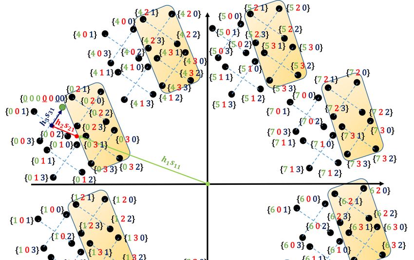
MULTI-USER JOINT MAXIMUM-LIKELIHOOD DETECTION IN UPLINK NOMA-IOT NETWORKS: REMOVING THE ERROR FLOOR
2

vector w ∈ CL×1 is given by w ∼ CN (0, N20 IL ). At the BS a           TABLE I: Computational cost in terms of real operations
channel state information (CSI) for each device is supposed to                       Multiplier                    Adder            Comparator
be available, and the received signal powers are presumed to                   P
                                                                               K                               P
                                                                                                               K                    P
                                                                                                                                    K
                                                                      SIC 6L         Mi + 4L(K − 1) (6L − 1)         Mi + 4L(K − 1)   (Mi − 1)
be correctly measured using the pilot√signals, such that kh1 k >               i=1                             i=1                    i=1
kh2 k > · · · > khK k, where hk = Pk ck , k = 1, · · · K, and                                 Q
                                                                                              K                            Q
                                                                                                                           K           Q
                                                                                                                                       K
                                                                     JML    (4LK + 2L)             Mi   (4LK + 2L − 1)           Mi         Mi − 1
the symbol k.k denotes the Frobenius norm.                                                   i=1                           i=1        i=1

   The information bitstream is modulated as complex symbol
xk ∈ C, k = 1, · · · , K, where it takes its value from the
                                         T
alphabet χk = [sk1 , sk2 , · · · , skMk ] , and the symbol sknk is   which is quite possible since it is an uplink communication and
the nth                                                              the JML is implemented at the BS, the JML does not cause a
          √       p point in Mk -ary modulation order of Dk .
      k constellation
                                                                     latency due to computational time. Besides, this computational
|sknk | = ǫk = ǫb log2 Mk for Dk , where ǫk is the symbol
energy and ǫb is the bit energy. We consider an adaptive             burden can be considered as acceptable, especially if we take
modulation that uses Mk -PSK with Gray coded mapping.                into account the performance improvement by MRC-JML.
   1) MRC-SIC detector: In SIC detector, IoT devices’ sym-
bols are detected serially. Initially, the symbols of the IoT                        III. E RROR P ERFORMANCE A NALYSIS
device with strongest gain channel is detected. Then, the
                                                                        In this section, we analyse the error performance of IoT
contribution of these detected symbols to received signal is
                                                                     uplink-NOMA system with JML. We derive an analytic ex-
removed, producing a second signal to detect the IoT device’s        pression of the upper bound for the BER in fading channels.
symbols with second-best channel condition. This process is
                                                                     For the purpose of a comprehensive study, we assume that the
repeated until the symbols of the last IoT device with weakest       IoT device of order k sends its data according to an appropriate
channel condition are detected. Consequently, the procedure          order modulation Mk , which depends on the channel quality.
is summarized as
                                                                        For the representation simplicity, let us start by considering
                                                   2
              x̂k = argmin kySIC,k − hk sknk k ,              (2)    a system composed of three IoT devices. The Fig. 1 shows the
                      sknk                                           superposed symbols, where the D1 chooses its symbols from
where k = 2, · · · , K, nk = 1, · · · , Mk , and                     8-PSK constellation (M1 = 8) and both the others devices: D2
                                                                     and D3 from a quadrature phase constellation (M2 = 4 and
               ySIC,k = ySIC,k−1 − hk−1 x̂k−1 ,               (3)    M3 = 4). It is worth mentioning that these constellation orders
where ySIC,1 = y, and x̂1 = argmin ky − h1 s1n1 k .
                                                       2             depend to the channel quality. The first three bits1 belong to
                                    s1n1                             D1 , the following two bits belong to D2 and the last two bits
   Although the procedure seems simple to implement, un-             belong to D3 . Thus, the binary bit representations of the three
fortunately, it suffers from the error floor. To recover each        symbols are given in the form of {b11 b12 b13 b21 b22 b31 b32 },
signal, the detector treats the remaining low power signals as       where the first sub-index represents the device and the second
interference, thus an error floor occurs. Increasing the number      represents the bit order within the symbol.
of antennas at the receiver may improve the performance of              For convenience, we assume that the superimposed se-
SIC in low SNR, but can not remove the error floor [6].              quence {000,   00, 00} that matches the symbols      x1 = s11 =
   2) MRC-JML detector: To avoid the drawback of the SIC             exp j π8 for D
                                                                               
                                                                                           x  = s    =  exp   j π
                                                                                                                  
                                                                                       1 ,  2     21            4   for D 2 and x3 =
detector, we suggest to jointly recover (i.e., optimal detection)    s31 = exp j π4 for D3 is received at the BS. Then, we proceed
                                                                                     
the transmitted signals from IoT devices. The JML detector           to analyze the BER of the first bit (bk1 = 0) for each of the
accomplishes an exhaustive search to simultaneously decode           three devices. In view of symmetry of M-PSK modulation, it
all signals x1 , x2 , · · · , xk as follows                          is evident that the BER is unchanged when bk1 = 1, therefore,
                                             XK         2            the study is restricted on the case of bk1 = 0. Since the BS
     [x̂1 , x̂2 , · · · , x̂k ] = argmin y −    hk sknk .     (4)
                             sknk          k=1                       relies on ML detector to detect the symbols, it is clear that
                                                                     an error happens if the ML selects the device symbol with
   Regardless of the order of selection, the JML traits the          first bit bk1 = 1. Fig. 1a shows the location of the erroneous
signals the same by realizing a full joint search for all possible
                                                                     symbols for D1 (shaded area) when the JML selects one of the
combinations [h1 s1n1 , h2 s2n2 , · · · , hK sKnK ], which avoids
                                                                     superimposed symbols with the first bit equal to one, i.e., the
an error floor.                                                      lower half-circle of an 8-PSK constellation with Gray coded
   3) Computational complexity: The computational complex-
                                                                     bit mapping (see Fig. 2). It is simple to notice that the number
ity comparison for MRC-JML and MRC-SIC is given in Table
                                                                     of erroneous symbols after this wrong decision is equal to the
I. The complexity of MRC-JML increases exponentially with
                                                                     all possible symbols of the devices D2 and D3 superimposed
the increase of K and Mk whereas the complexity of MRC-
                                                                     with the four symbols of D1 ( 28 × 4 × 4 symbols). Thus, if we
SIC increases linearly with the same factors. However, this
                                                                     consider a K IoT devices with Mk -ary order for each      Dk , the
complexity reflects the required computational capacity rather                                                               QK
                                                                     number of erroneous symbols is clearly equal to 21 i=1 Mi .
than computing time. One can easily see from (4) that the
                                                                     Regarding the others devices (the remaining K − 1 devices),
search in JML is independent so that it can be computed
                                                                     the same number of errors can be noticed, see Fig. 1b and
in parallel and be compared in the final stage, whereas the
SIC detection (2)-(3) should be implemented sequentially.              1 For an easy-follow illustration, we have adopted an octal representation
Therefore, as long as we have enough computational capacity,         of the symbols for D1 , and quaternary representation for D2 and D3 .
MULTI-USER JOINT MAXIMUM-LIKELIHOOD DETECTION IN UPLINK NOMA-IOT NETWORKS: REMOVING THE ERROR FLOOR
3

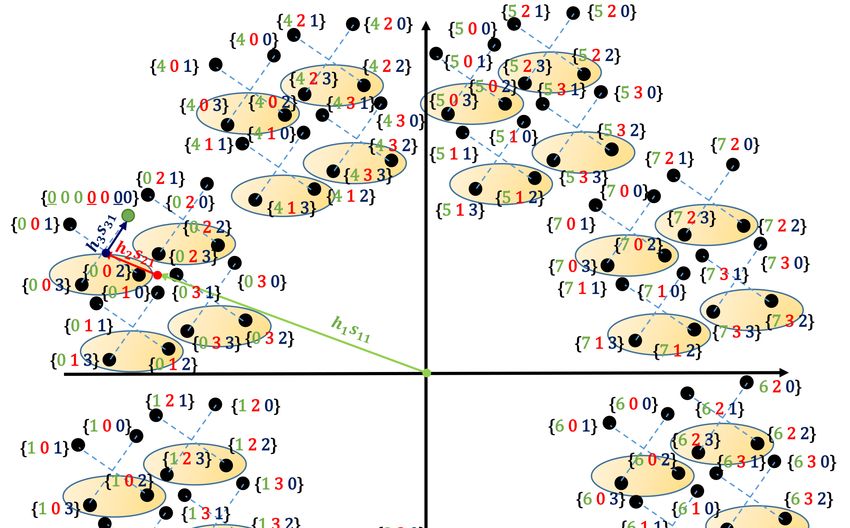
       (a) Error pattern for Device1 (D1 )             (b) Error pattern for Device2 (D2 )                 (c) Error pattern for Device3 (D3 )
Fig. 1: Signal space diagram for superposed symbols of three IoT devices (8-PSK with two 4-PSK) with Gray coded bit
mapping.

                                                                           sk1 and the superimposed symbols with the erroneous symbol
                                                                           (first bit bk1 = 1). Table II summarizes the elements of dD        k
                                                                                                                                                .
                                                                                                                      PK           √ Dk i
                                                                           It is noteworthy that the distances k i=1 hi ǫi di (m) k
                                                                           are the distances between Mk -PSK symbols in a new space
                                                                           rotated by hk , k = 1, · · · , K, and as long as the symbols have
                                                                           experienced the same rotation, in consequence, the symmetry
                                                                           and error patterns are retained. As a result of these properties
                                                                           and the circularity of PSK modulation, if we replace the term
                                                                           sk1 by any other terms sknk , where nk = 2, · · · , Mk , the
                                                                           elements of dk are the same without dealing with order, then
                                                                           the components of dD    i
                                                                                                     k
                                                                                                         for i 6= k, which contribute to the
                                                                           conditional PEP turns into the same. This means that the
                                                                           conditional PEP for different IoT devices, differs from each
             Fig. 2: The effective distances for D1 .                      other in virtue of vectors Ek1 .
                                                                              At this juncture, we have study the error patterns for
                                                                           symbol sk1 , it is easy to show that the number of errors
Fig. 1c for illustration. By examining the error patterns of the           is constantly the same for the remaining of symbols sknk ,
Fig. 1b and Fig. 1c, we observe the same number of errors                  nk = 2, · · · , Mk . From the symmetry of the Mk -PSK
                                                                           constellation (see Fig. 2), we can notice that the distances
which equal to 8 × 42 × 4 and 8 × 4 × 24 for D2 and D3 ,                   between the points which are located in upper half-circle
respectively. The difference between errors of distinct devices            and those situated in lower half-circle are equal in pairs
is due to error pattern that depends to the arrangement of the             with respect to the right and left semicircle, consequently,
components of signals (power) within the overlapped symbols                there are a total of M4k different vectors dD           k
                                                                                                                                     k
                                                                                                                                       which de-
at receiver.                                                                                    √ −1 h                                       iT
                                                                           pend to Ekn = ǫk               skn − sk Mk +1 , · · · , skn − skMk ,
   Based on the result above, we designate the distances be-                                                        2
tween the first symbol sk1 of each IoT Dk , k = 1, · · · , K, and          n = 1, · · · , M4k . Thus, we consider only the contribution of
                                                                           Mk
the M2k erroneous symbols sknk , nk = M2k + 1, · · · , Mk , by               4 symbols located in the right quadrant to calculate the
                    √      h                                  iT           upper bound. Additionally, by examining the remaining of
the vector Ek1 = ǫk −1 sk1 − sk Mk +1 , · · · , sk1 − skMk ,               bits bklog2 Mk from symbols skn , n = 1, · · · , M4k , and taking
                                     2
and the distances between√sk1 with the symbols of the alphabet             into consideration the approximated formula of the probability
χk by the vector dk = ǫk −1 (sk1 ⊗ 1Mk − χk ), where ⊗                     of error [13, Eq. (10)] which ties to the right quadrant, i.e.,
denotes the Kronecker product, and 1Mk is the all ones  QKvector           utilizing only the M4k symbols2 , and by supposing equally
of dimension Mk × 1. Correspondingly, the total 12 i=1 Mi                  likely symbols in the new space diagram, we get
pairwise error probabilities (PEP) following the erroneous                                                                     Mk
decision between the symbol sk1 with the symbols sknk ,                                     P r (e | h1 , · · · , hK ) ∼
                                                                                                                       =              Prq ,          (6)
                                                                                                                           2 log 2 Mk
nk = M2k + 1, · · · , Mk , conditioned on the vectors hk ,
k = 1, · · · , K are given by                                              where
                                                     √ Dk
                                                                                          Mk            √                                √
                                                                                       k hk ǫk dD                                      hi ǫi dD
                                                                                                                            PK                       
                                                                                                kn (m) +                                      i (m) k
                                                                                                  k                                             k
                                              PK                    !
                                                                                   4
                                          k    i=1 hi ǫi di (m) k                4 X                                           i=1
                                                                                                                                i6=k
P r (sk1 → sknk | h1 , · · · , hK ) = Q             √                  ,   Prq =     Q                 √                                              ,
                                                      2N0                            Mk                                      2N0
                                                                                          n=1
                                                                    (5)                                                                              (7)
                                               ∈ C( 2 i=1 Mi )×1 , i =
                                                    1 QK
where m = 1, · · · , 21 i=1 Mi , and dD
                       QK                  k
                                         i
1, · · · , K , denotes the distances between the symbol under test           2 The   analysis for Mk = 2 is identical to Mk = 4.
MULTI-USER JOINT MAXIMUM-LIKELIHOOD DETECTION IN UPLINK NOMA-IOT NETWORKS: REMOVING THE ERROR FLOOR
4

                                                                  TABLE II: Distances to erroneous symbols
                     Distances                 D                                    D                                                   D                                         D
                                           d1 k                                   d2 k                        ···                      dk k                     ···              dKk
          Devices

                    D1             E11 ⊗ 1QK                         1 M1       ⊗ d2 ⊗ 1QK                    ···   1 1 Qk−1 Mi ⊗ dk ⊗ 1QK                      ···   1 1 QK−1 Mi ⊗ dK
                                                       i=2 Mi              2                     i=3 Mi                 2    i=1                   i=k+1
                                                                                                                                                           Mi
                                                                                                                                                                       2    i=1

                    D2             d1 ⊗ 1 1        QK              1M1 ⊗ E21 ⊗ 1QK                            ···   1 1 Qk−1 Mi ⊗ dk ⊗ 1QK                      ···   1 1 QK−1 Mi ⊗ dK
                                               2       i=2 Mi                                    i=3 Mi                 2    i=1                   i=k+1
                                                                                                                                                           Mi
                                                                                                                                                                       2    i=1

                    Dk             d1 ⊗ 1      1 QK               1M1 ⊗ d2 ⊗ 1           1 QK                 ···   1Qk−1            ⊗ Ek1 ⊗ 1    QK
                                                                                                                                                         Mi     ···   1 1 QK−1 Mi ⊗ dK
                                               2       i=2 Mi                            2       i=3 Mi                     i=1 Mi                 i=k+1               2    i=1

                    DK             d1 ⊗ 1 1        QK
                                                             Mi   1M1 ⊗ d2 ⊗ 1 1 QK                      Mi   ···   1Qk−1 Mi ⊗ dk ⊗ 1 1 QK                 Mi   ···   1QK−1 Mi ⊗ EK1
                                               2       i=2                               2       i=3                        i=1               2    i=k+1                   i=1

where dD kn = 1 k−1 Mi ⊗ Ekn ⊗ 1 K      Mi . Incorporating (7)                                                                          IV. N UMERICAL R ESULTS
           k     Q              Q
                  i=1             i=k+1
into (6), yields
                                                                                                                 In this section, we validate the derived expressions by using
                                                           Mk
                                                            4
                                                                             Dk                              computer simulations 3 . In Fig. 3a and Fig. 3b, we present
                                                                           k δnm k
                                                                                       
                                        2
     P r (e | h1 , · · · , hK ) ∼
                                             X
                                =                Q                          √                ,     (8)        BER comparisons for MRC-JML and MRC-SIC with respect
                                     log2 Mk n=1                              2N0                             to SNR for L = 4. In Fig. 3a, we consider a fixed modulation
       Dk            √D                    Dk                √                                                where six (K = 6) IoT devices emitting their data using 4-PSK
           = hk ǫk dknk (m) + K
                                          P
where δnm                       i=1 hi ǫi di (m). Hence, for
                                i6=k                                                                          (i.e., Mk = 4, ∀k) constellation. In Fig. 3b, each device sends
the probability of union of events, we write the upper bound                                                  data by using its own constellation order in a system composed
by
                                                                                                              of four (K = 4) IoT devices. By exploiting the CSI provided
                                                   Mk      1 QK M
                                       4                   2  i=1 i                  D
                                                                                                 !            by the BS via the broadcast signaling, commonly, to provide
                                 2    X                      X                    k δnm
                                                                                      k
                                                                                        k
 P r (e | h1 , · · · , hK ) ≤                                               Q      √                 .        a considerable spectrum efficiency in adaptive modulation,
                              log2 Mk n=1                    m=1
                                                                                     2N0
                                                                                                     (9)      a low order (stronger modulation) is chosen for the worst
Due to the characteristic of the vectors h1 , · · · , hk , we have                                            channel conditions, while high order (weaker modulation) is
                                                                                                              adopted for a high channel condition. Hence, the orders are
                                                               
 D                                  D                      PK                      D
  k
δnm ∼ CN            0, Pk ǫk σk2 |dknk (m)|2 +                  i=1    Pi ǫi σi2 |di k (m)|2 .
                                                                i6=k                                          chosen as follows: M1 =32, M2 =16, M3 =8, and M4 =4. In
                                                                Dk     2
Like [7], if we denote by Γkm = kδ2Nnm k
                                          and considering                                                     both scenarios, we can easily observe that the MRC-JML
                                      0
L branches of uncorrelated signals y ∈ CL×1 received at                                                       detector outperforms the MRC-SIC detector significantly. It
BS, then Γkm follows Erlang distribution with parameter                                                     is evident that the MRC-JML can remove completely the
                                                                                                              error floor in the high SNR regime. Differently, the MRC-
ΥD             ζk |dD                          ζi |dD
           1               2
                                    PK                    2
 nm =
   k
           2        kn (m)| +
                      k
                                        i=1         i (m)|
                                                      k
                                                                               and PDF given                  SIC detector suffers greatly from the error floor and presents
                                        i6=k
as                                                                                                            a poorer performance. Indeed, none of the symbols can be
                                        γ L−1
                                                                     
                                                                           −γ
                                                                               
                                1                                                                             detected (i.e., Pk (e) ∼ 0.5) by using MRC-SIC. This clearly
        PΓkm (γ) =                           L exp                              .                (10)
                             (L − 1)!
                                      
                                          Dk                               ΥDk
                                                                            nm
                                                                                                              shows that the JML enables the MMTC by supporting higher
                                       Υnm                                                                    number of devices (i.e., K = 4, 6) in the same resource
                         2                                                                                    block. Besides, it also allows using higher modulation orders,
where ζk = PkNǫk0σk is the received signal-to-noise ratio (SNRk )
                                                                                                              which is quite promising considering that the SIC detector fails
of Dk . Therefore, by averaging the BER Pk (e) of IoT Dk over
the distribution of Γkm , it becomes                                                                          to detect BPSK symbols even in two-user scenario [5], [6].
                             Mk 1 QK
                                                                                                              Furthermore, the analytical results derived from expressions
                              4 2  i=1 Mi                                                                     (12)-(13) match well with the simulation results regardless of
                                                       ∞
                                                              √
                                               Z
              2    X               X
  Pk (e) ≤                                                 Q ( γ) PΓkm (γ) dγ. (11)                           the number of users (K) or modulation orders (Mk ) which
           log2 Mk                                 0
                             n=1   m=1                                                                        validates our analysis. The upper bounds are very tight in
With the aid of [7], we obtain (12) as the upper bound UPk (e) ,                                              the high SNR regime and it is also frequently for all upper
where Pk (e) ≤ UPk (e) . The expression (12) is the general                                                   bounds in communication systems. On the other hand, the
form of BER upper bound for the k th IoT device where                                                         upper bound is not tight in low SNR, and this is due to
k = 1, · · · , K, using Mk -ary PSK. From Fig. 1a and Fig.                                                    the fact that in this regime, the upper bound is a sum of
2, we can deduce that the vector Ek1 contains the smallest                                                    PEPs with very large and close values. Moreover, once the
distances (with the minimum norm) in comparison with those                                                    performances of MRC-JML are compared according to the
obtained in the same quadrant; hence, their conditional PEP                                                   receiving SNRk , the performances of devices with stronger
P r (sk1 → sknk | h1 , · · · , hK ) dominate the BER for high SNR.                                            gain channel surpass those of severe channels in the scenario
Then, for Mk > 4 the upper bound (12) may be approximated                                                     of fixed modulation. Since the error patterns are the same (i.e.,
using only Ek1 to get (13). It can be noticed that equations                                                  the same value of distances Ekn and dk which contribute
(12) and (13) are monotonically decreasing functions in terms                                                 to compute the PEP for each device k), this superiority is
of superimposed SNRk of different IoT devices, which deter-
                                                                                                                 3 We assume that ǫ = 1, ∀k, and P = · · · = P , which is the worst
mines the performance of each device according to its quality                                                                       k                 1             K
                                                                                                              case in terms of interference. The channel conditions are varied according to
of the channel and the transmission power with the order of                                                                                                       2
                                                                                                              the dominant gain channel by fixing variances as σk = 2σk+12    with σ12 = 0
modulation.                                                                                                   dB.
MULTI-USER JOINT MAXIMUM-LIKELIHOOD DETECTION IN UPLINK NOMA-IOT NETWORKS: REMOVING THE ERROR FLOOR
5

                                                                                       
                                                                                    M
                                                                              max 1, 4k                     1
                                                                                                                QK
                                                                                                            2    i=1 Mi                 XL−1 2l                                                                            
                                                     1                                   X                       X                                                                − 12                                −l
                              UPk (e)      =                                                                                    1−                              1+          2/ΥDk
                                                                                                                                                                               nm                   2ΥDk
                                                                                                                                                                                                      nm       +4                 ,                (12)
                                             max (2, log2 Mk )                           n=1                    m=1
                                                                                                                                                l=0      l

                                                                    1
                                                                        QK
                                                                    2    i=1 Mi                    XL−1 2l                                        − 12                            −l 
                                                  ∼    1                 X
                                ŨPk (e)          =                                  1−                                          1 + 2/ΥDk
                                                                                                                                        1m                      2ΥD
                                                                                                                                                                  1m + 4
                                                                                                                                                                   k
                                                                                                                                                                                                ,   Mk > 4.                                        (13)
                                                    log2 Mk             m=1
                                                                                                           l=0          l

       100                                                                               100                                                                                100
                                                                                                                                                                                                                                  Dash Lines: SIM
                                                                                                                                                                                                                                  Solid Lines: Analyt.
                                                                                                                                                                                                                                  Eq (12)
       10-1                                                                              10-1                                                                               10-1

                                                                                                                                                                                                                         L = 1
       10-2                                                                              10-2                                                                               10-2

                                                                                                         IoT D1 (32-PSK)                                                                                                                       IoT D1
 BER

                       IoT D1 (4-PSK)                                              BER                                                                                                                                                         IoT D2
       10-3                                                                              10-3

                                                                                                                                                                      BER
                                                                                                         IoT D2 (16-PSK)                                                    10-3
                                                                                                                                                                                                               L = 2
                       IoT D2 (4-PSK)                                                                                                                                                                                                          IoT D3
                                                                                                         IoT D3 (8-PSK)
                       IoT D3 (4-PSK)
                       IoT D4 (4-PSK)                                                                    IoT D4 (4-PSK)
       10-4                                                                              10-4
                       IoT D5 (4-PSK)                                                                                                                                       10-4                                        L = 4
                                                                                                    Dot lines: MRC-SIC (SIM)
                       IoT D6 (4-PSK)
                                                                                                    Dash lines: MRC-JML (SIM)
       10-5       Dot lines: MRC-SIC (SIM)                                               10-5       Dash-Dot lines: Analyt. Eq.(12)
                                                                                                                                                                            10-5        L = 8
                  Dash lines: MRC-JML (SIM)                                                         Solid Lines: Analyt. approxi. Eq. (13)
                  Solid Lines: Analyt. Eq. (12)
       10-6                                                                              10-6
              0           5           10           15          20       25    30                0           5          10           15          20      25       30         10-6
                                                                                                                                                                                   0        5       10          15           20          25              30
                                           Transmit SNR (dB)                                                                Transmit SNR (dB)
                                                                                                                                                                                                         Transmit SNR (dB)

                                             (a)                                                                              (b)                                                                         (c)
Fig. 3: Error performance of uplink IoT NOMA: BER vs Transmit SNR (dB). a) L = 4, K = 6, Mk = 4, ∀k. b) L = 4,
K = 4, M1 = 32, M2 = 16, M3 = 8, M4 = 4 c) L = 1, 2, 4, 8, K = 3, Mk = 4, ∀k.

explained by the quality of signal-to-interference-plus-noise                                                                        BER for multi-user is derived by assuming adaptive M -PSK
ratio SINRk for each device k. Whereas, when decreasing                                                                              modulation and arbitrary K active IoT devices.
the modulation order for devices with a bad channel, it is
                                                                                                                                                                                       R EFERENCES
noteworthy that the improvement of their performance is due
to the compensation for the effect of the worst channel. This                                                                         [1] A. E. Mostafa et al., “Connection Density Maximization of Narrowband
                                                                                                                                          IoT Systems With NOMA,” IEEE Trans. on Wirel. Commun., vol. 18,
is caused by the enlarging of the minimum distance between                                                                                no. 10, pp. 4708–4722, 2019.
symbols in the low order constellation.                                                                                               [2] A. Emir et al., “DeepMuD: Multi-user Detection for Uplink Grant-
   Finally, to emphasis the benefit of diversity order provided                                                                           Free NOMA IoT Networks via Deep Learning,” IEEE Wirel. Commun.,
                                                                                                                                          vol. 10, no. 5, pp. 1133–1137, 2021.
by the JML detector, in Fig. 3c, we present the BER perfor-                                                                           [3] S. A. Tegos et al., “Slotted ALOHA with NOMA for the Next Gen-
mance of combining multiple signals at the BS for three (K =                                                                              eration IoT,” IEEE Trans. Commun., vol. 68, no. 10, pp. 6289–6301,
3) active IoT devices with different antenna (L = 1, 2, 4, 8)                                                                             2020.
                                                                                                                                      [4] Z. Ding et al., “Unveiling the Importance of SIC in NOMA Systems
situations. As illustrated in Fig. 3c, the performance improves                                                                           - Part 1: State of the Art and Recent Findings,” IEEE Commun. Lett.,
each time the number of receiving antennas is increased owing                                                                             vol. 24, no. 11, pp. 2373–2377, 2020.
to the improvement of quality of the link. We can also see                                                                            [5] F. Kara and H. Kaya, “BER Performances of Downlink and Uplink
                                                                                                                                          NOMA in the Presence of SIC Errors over Fading Channels,” IET
that the theoretical results correspond well with the results                                                                             Commun., vol. 12, no. 15, pp. 1834–1844, 2018.
of the simulation, this matching improves even at low SNR                                                                             [6] F. Kara and H. Kaya, “Error Probability Analysis of NOMA-Based
because of the enhancement in the power of the link due to                                                                                Diamond Relaying Network,” IEEE Trans. on Veh. Technol., vol. 69,
                                                                                                                                          no. 2, pp. 2280–2285, 2020.
the technique of combining at BS. Likewise, one can easily                                                                            [7] J. S. Yeom et al., “BER Performance of Uplink NOMA with Joint
see that the MRC-JML reaches the full diversity order which                                                                               Maximum-Likelihood Detector,” IEEE Trans. Veh. Technol., vol. 68,
corresponds to the number of antennas L. This order is noticed                                                                            no. 10, pp. 10 295–10 300, 2019.
                                                                                                                                      [8] F. Kara and H. Kaya, “Improved Error Performance in NOMA-based
by checking the slope of BER curves in all figures.                                                                                       Diamond Relaying,” in 2020 IEEE Microw. Theory and Techn. in Wirel.
                                                                                                                                          Commun. (MTTW), vol. 1, 2020, pp. 151–156.
                                                                                                                                      [9] M. B. Shahab et al., “Index Modulation Aided Uplink NOMA for
                                                   V. C ONCLUSION                                                                         Massive Machine Type Communications,” IEEE Wirel. Commun. Lett.,
   This paper presents a reliable multi-user uplink IoT scheme                                                                            vol. 9, no. 12, pp. 2159–2162, 2020.
                                                                                                                                     [10] H. Semira and F. Kara, “Error Performance of Uplink SIMO-NOMA
through SIMO-NOMA. By applying MRC-JML (i.e., optimum                                                                                     with Joint Maximum-Likelihood and Adaptive M-PSK,” in 2021 IEEE
detector) instead of MRC-SIC (i.e., iterative detector com-                                                                               Internat. Black Sea Conf. Commun. Netw. (BlackSeaCom), 2021.
monly used in the literature) to detect data from several IoT                                                                        [11] M. B. Shahab et al., “Receiver Design for Uplink Power Domain NOMA
                                                                                                                                          with Discontinuous Transmissions,” IEEE Commun. Lett., 2021, Early
devices, the proposed scheme has proven its effectiveness to                                                                              Access.
discard the error floor. In addition, the JML attains the full                                                                       [12] 3GPP, “NR; Physical Channels and Modulation,” Mar. 2021, TS 38.211
diversity order and this confirms the superiority of the JML                                                                              Release 16, v16.5.0.
                                                                                                                                     [13] Jianhua Lu et al., “M-PSK and M-QAM BER Computation Using
comparatively to SIC. A comprehensive analysis of BER based                                                                               Signal-Space Concepts,” IEEE Trans. on Commun., vol. 47, no. 2, pp.
on union bound approach is studied. A tight upper bound of                                                                                181–184, 1999.
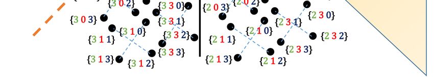
MULTI-USER JOINT MAXIMUM-LIKELIHOOD DETECTION IN UPLINK NOMA-IOT NETWORKS: REMOVING THE ERROR FLOOR
You can also read