Official Basketball Rules 2018 Basketball Equipment
←
→
Page content transcription
If your browser does not render page correctly, please read the page content below
Official Basketball Rules 2018
               Basketball Equipment

                              As approved by

                          FIBA Central Board
                    Mies, Switzerland, 16th June 2018

                        Valid as of 1st October 2018

            This is a working document of the final version.
All changes are marked with yellow colour (version: yellow tracking v2.0)
        The final version may have few minor editorial changes.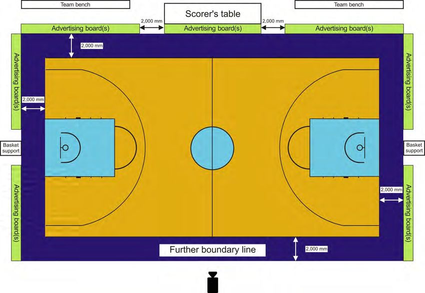
Page 2 of 26 OFFICIAL BASKETBALL RULES 2018 June 2018
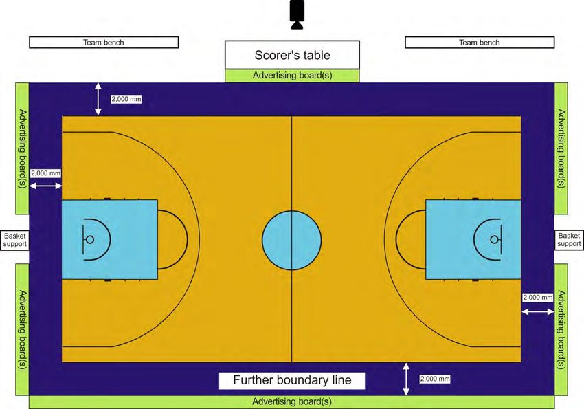
TABLE OF CONTENTS
1     Backstop unit......................................................................................................................................6
2     Backboard...........................................................................................................................................7
3     Basket ring ..........................................................................................................................................8
4     Basket net .........................................................................................................................................10
5     Backboard support structure ........................................................................................................10
6     Padding ..............................................................................................................................................11
7     Basketballs .......................................................................................................................................11
8     Game clock .......................................................................................................................................12
9     Scoreboard/Videoboard .................................................................................................................13
10    Shot clock .........................................................................................................................................14
11    Signals ...............................................................................................................................................15
12    Player foul markers .........................................................................................................................16
13    Team foul markers ...........................................................................................................................16
14    Alternating possession arrow .......................................................................................................16
15    Playing floor ......................................................................................................................................16
16    Playing court.....................................................................................................................................18
17    Lighting ..............................................................................................................................................18
18    Advertising boards ..........................................................................................................................24
19    Spectator areas ...............................................................................................................................25
20    References........................................................................................................................................26

TABLE OF DIAGRAMS
Diagram 1            Backstop unit (Option 1) ...................................................................................................6
Diagram 2            Backstop unit (Option 2) ...................................................................................................6
Diagram 3            Backboard markings .........................................................................................................8
Diagram 4            Rigidity of the backboard glass.......................................................................................8
Diagram 5            Basket ring ..........................................................................................................................9
Diagram 6            Ring mounting plate ..........................................................................................................9
Diagram 7            Ring mounting plate for existing baskets ......................................................................9
Diagram 8            Backboard padding .........................................................................................................11
Diagram 9            Scoreboard for Level 1 (example of the layout) .........................................................14
Diagram 10           Shot clock display unit and duplicate game clock, for Levels 1 and 2
                     (example of the layout) ...................................................................................................15
Diagram 11           Alternating possession arrow (Example of the layout) ............................................16
Diagram 12           Playing court ....................................................................................................................18
Diagram 13           Advertising boards – main camera table side ...........................................................24
Diagram 14           Advertising boards – main camera opposite side .....................................................25
Diagram 15           Spectators' line of visibility............................................................................................25

June 2018                                        OFFICIAL BASKETBALL RULES 2018                                                              Page 3 of 26
Page 4 of 26 OFFICIAL BASKETBALL RULES 2018 June 2018
Basketball Equipment

Throughout this section entitled Basketball Equipment, all references made to a timer, scorer,
shot clock operator, etc. in the male gender also apply to the female gender. It must be
understood that this is done for practical reasons only.

Introduction
The Basketball Equipment section of the Official Basketball Rules specifies all basketball
equipment required at a game. Reference to high level competitions indicates that the equip-
ment is essential and imperative for this level and strongly recommended for medium level and
all of the other competitions. Reference to medium level competitions indicates that the equip-
ment is essential and imperative for this level and strongly recommended for all other compe-
titions.

This Appendix shall be used by all parties involved directly in the game as well as by basketball
equipment manufacturers, local organisers and FIBA for its equipment approval programme and
to establish national and international standards.
The competitions are divided into 3 levels:

•   High level competitions (Level 1):
    Main FIBA official competitions, as defined in Book 2 – Chapter I of the FIBA Internal
    Regulations governing the FIBA Competitions.
    The facilities and equipment required for the following main FIBA official competitions are
    subject to FIBA approval (Levels 1 and 2): Olympic Tournaments, Olympic Qualifying
    Tournaments; FIBA Basketball World Cup and FIBA Women’s Basketball World Cup
    including qualification games, FIBA U-17 and U-19 Basketball World Cup for Men and
    Women; Continental Cups for Men and Women.
    All equipment at these competitions must be FIBA approved Level 1 and must display the
    FIBA Equipment & Venue logo in the FIBA approved layout.

•   Medium level competitions (Level 2):
    All other FIBA official competitions as defined in Book 2 – Chapter I of the FIBA Internal
    Regulations governing the FIBA Competitions, and high-level competitions of the national
    federations.

•   Other competitions (Level 3):
    All other competitions not included in the above.

Notes: 1.        All measurement tolerances are according to EN/DIN/ISO Standard 286 (see
                 References [1]) except where other values are explicitly stated.
            2.   Reference is made to the FIBA publication "FIBA Guide to Basketball Facilities".

June 2018                         OFFICIAL BASKETBALL RULES 2018                       Page 5 of 26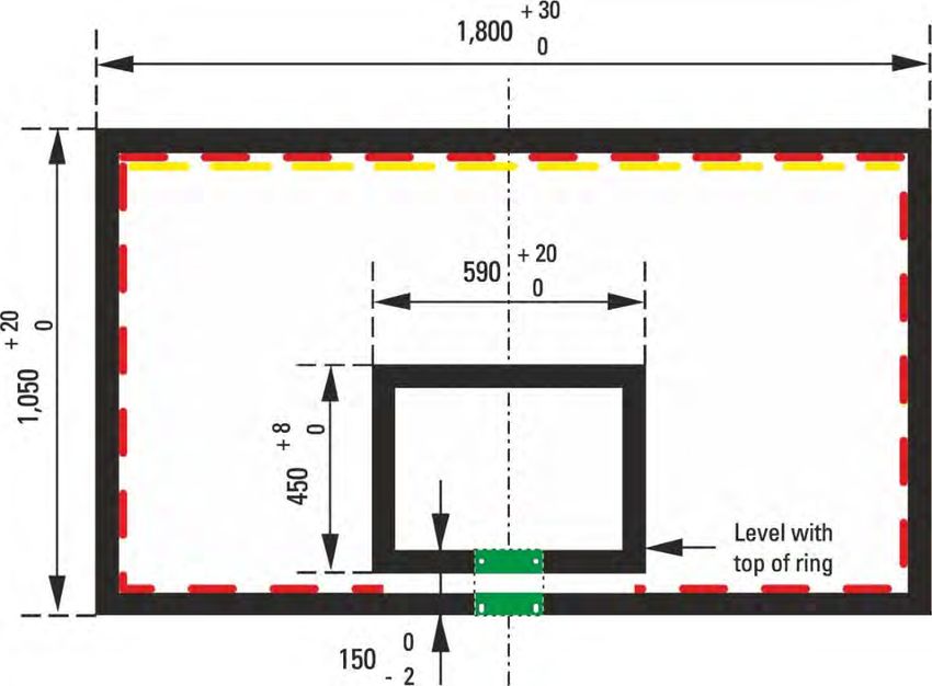
1       Backstop unit
        There shall be 2 backstop units (Diagram 1 or 2), 1 placed at each end of the playing
        court and each consisting of the following parts:
        • 1 backboard.
        • 1 basket ring with a ring mounting plate.
        • 1 basket net.
        • 1 basket support structure.
        • Padding.

        Diagram 1     Backstop unit (Option 1)

        Diagram 2     Backstop unit (Option 2)

Page 6 of 26                   OFFICIAL BASKETBALL RULES 2018                       June 2018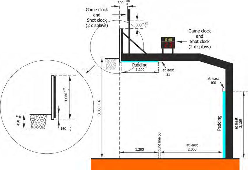
2      Backboard
2.1    The backboards shall be made of a suitable transparent material (for Level 1 and 2, of a
       tempered safety glass), made in one piece, non-reflective, with a flat front surface and
       shall:
       • Have a protective framework of the backboard support structure around the outer
             edge.
       • Be manufactured such that, if broken, the pieces of glass do not split off.
2.2    For Level 3, the backboards may be made of other material(s) painted white, but must
       meet the other above specifications.
2.3    The backboards shall measure 1,800 mm (+ a maximum of 30 mm) horizontally and
       1,050 mm (+ a maximum of 20 mm) vertically.
2.4    All lines on the backboards shall be:
       • In white, if the backboards are transparent.
       • In black, if the white painted backboards are non-transparent.
       • 50 mm in width.
2.5    The borders of the backboards shall be marked with a boundary line (Diagram 3) and an
       additional rectangle behind the ring as follows:
       • Outside dimensions: 590 mm (+ a maximum of 20 mm) horizontally and 450 mm (+ a
             maximum of 8 mm) vertically.
       • The top edge of the base of the rectangle shall be level with the top of the ring and
             150 mm (- 2 mm) above the bottom edge of the backboard.
2.6    For Levels 1 and 2, each backboard shall be equipped with lighting around its perimeter,
       mounted on the inside borders of the backboards and which lights up in red only when
       the game clock signal sounds for the end of a quarter or overtime. The lighting shall be
       a minimum of 10 mm in width and cover a minimum of 90 % along the edge of the
       backboard glass area.
2.7    For Levels 1 and 2 each backboard shall be equipped with lighting along its perimeter at
       the top, mounted on the inside borders of the backboards, which lights up in yellow only
       when the shot clock signal sounds. The lighting shall be a minimum of 10 mm in width
       and be mounted directly below the red lighting for the game clock.

June 2018                     OFFICIAL BASKETBALL RULES 2018                        Page 7 of 26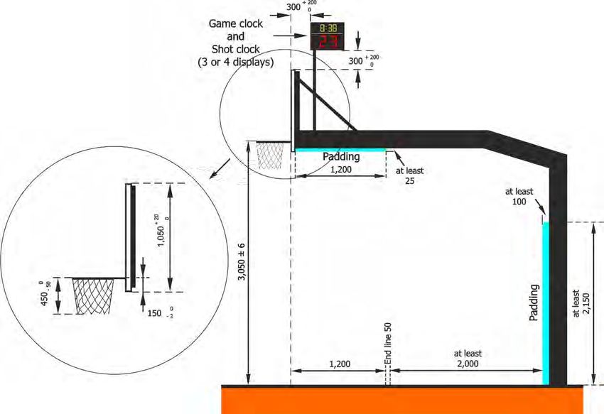
Diagram 3        Backboard markings
2.8     The backboards shall be firmly mounted on the backboard support structures at each
        end of the playing court at right angles to the floor, parallel to the endlines (Diagram 1 or
        2).
        The central vertical line on their front surfaces, extended down to the floor, shall touch
        the point on the floor which lies 1,200 mm from the centre point of the inner edge of each
        endline, on an imaginary line drawn at right angles to this endline.
2.9     Rigidity test for the backboard tempered safety glass:
        • When a square-shaped weight of 50 kg (250 mm wide and high, and 1,100 mm long)
             is applied along the centre of the backboard glass (without its frame), which is
             placed horizontally on 2 parallel wooden bars at a distance of 1,200 mm from each
             other (Diagram 4), the maximum vertical deformation shall be 3 mm.
        • When a basketball is dropped onto the backboard, it shall rebound from it with a
             minimum rebounding height of 50 %.

        Diagram 4       Rigidity of the backboard glass

3       Basket ring
3.1     The rings shall be made of solid steel and shall:
        • Have an inside diameter of a minimum of 450 mm and a maximum of 459 mm.
        • Be painted orange within the following Natural Colour System (NCS) FIBA approved
            spectrum (see References [2]):
            0080-Y70R                0090-Y70R               1080-Y70R
        • Have its metal a minimum of 16 mm and a maximum of 20 mm in diameter.
3.2     The net shall be attached to each ring in 12 places. The fittings for the attachment shall:
        • Not have any sharp edges or gaps,
        • Have gaps smaller than 8 mm, to prevent fingers from entering,
        • Not be designed as hooks for Level 1 and 2.

                                                              Attachment of the net (example)
Page 8 of 26                     OFFICIAL BASKETBALL RULES 2018                             June 2018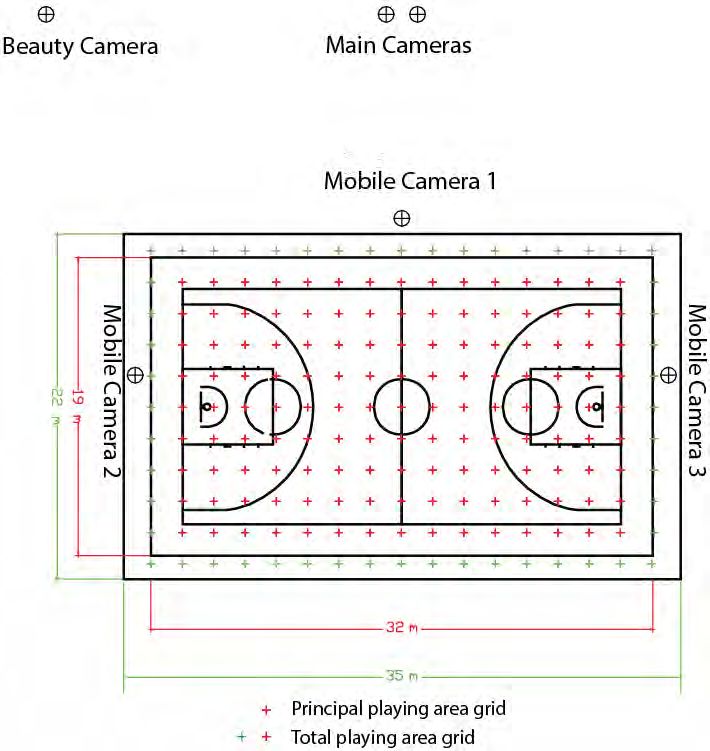
Diagram 5       Basket ring
3.3    The rings shall be fixed to the backboard support structures in such a way that any force
       applied to the ring cannot be transferred to the backboard itself. Therefore, there shall
       be no direct contact between the ring mounting plate and the backboard (Diagram 6).
3.4    The top edge of each ring shall be positioned horizontally, 3,050 mm (± a maximum of
       6 mm) above the floor, equidistant from the 2 vertical edges of the backboard.
3.5    The point on the inside circumference of the ring nearest the backboard shall be 151 mm
       (± a maximum of 2 mm) from the face of the backboard.

             Must not
          extend below
        the bottom edge
        of the backboard

       Diagram 6       Ring mounting plate
3.6    For existing basket support structures, it is recommended that the ring mounting plate
       be fixed to the framework according to the measurements given in Diagram 7.

             Must not
          extend below
        the bottom edge
        of the backboard

       Diagram 7       Ring mounting plate for existing baskets

June 2018                      OFFICIAL BASKETBALL RULES 2018                        Page 9 of 26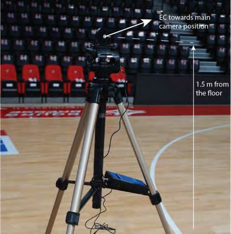
3.7     Pressure release rings with the following specifications shall be used for Levels 1 and 2
        and are recommended for Level 3:
        • It shall have rebound qualities close to those of the fixed ring. The pressure release
            mechanism shall ensure these characteristics, but not cause any damage to either
            the ring or the backboard. The design of the ring and its construction shall be such
            that the players' safety is ensured.
        • The pressure release rings shall have a 'positive-lock' mechanism which must not
            disengage until a static load of a minimum of 82 kg and a maximum of 105 kg has
            been applied vertically to the top of the ring at the most distant point from the
            backboard. The pressure release ring mechanism shall be adjustable within the
            given static load range.
        • When the pressure release mechanism is released, the front or the side of the ring
            shall rotate no more than 30 degrees and no less than 10 degrees below the original
            horizontal position.
        • After release and with the load no longer applied the ring shall return automatically
            and instantly to its original position. No fissures and no permanent deformation of
            the ring shall be observed.
        • Both rings must have identical rebound characteristics.
3.8     The rebound/elasticity of the ring and support system shall be within 35 % - 50 % energy
        absorption range of total impact energy and with a maximum differential of 5 % between
        both baskets on the same playing court.

4       Basket net
4.1     The nets shall be made of white cord and shall be:
        • Suspended from the rings.
        • Manufactured so that they check the ball momentarily as it passes through the
            basket.
        • No less than 400 mm and no more than 450 mm in length.
        • Manufactured with 12 loops to attach it to the ring.
4.2     The upper section of the net shall be semi-rigid to prevent:
        • The net from rebounding up through or over the ring, creating possible entangle-
            ment.
        • The ball from becoming trapped in the net or rebounding back out of the net.

5       Backboard support structure
5.1     For Level 1, only mobile or floor-fixed backboard support structures shall be used. This
        is also recommended for Level 2.
        For Levels 2 and 3, ceiling or wall mounted backboard support structures may also be
        used. Ceiling mounted backboards shall not be used in sports halls with a suspension
        height exceeding 10,000 mm in order to avoid excessive vibration in the support
        structure.
5.2     The backboard support structure shall be:
        • For Levels 1 and 2, at a distance of at least 2,000 mm including padding, measured
             from the outer edge of the endline (Diagram 1 or 2).
        • Of a bright colour, contrasting with the background, so that it is clearly visible to the
             players.
        • Secured to the floor so as to prevent any movement. If floor anchoring is not
             possible, an additional weight on the basket support base must be used to prevent
             any movement.
Page 10 of 26                   OFFICIAL BASKETBALL RULES 2018                            June 2018
• Adjusted such as that once the top edge of the ring is at a height of 3,050 mm from
the playing floor, this height cannot be changed.
5.3 The rigidity of the backboard support structure with ring shall fulfil the requirements of
the EN 1270 norms.
5.4 The visible vibration of the backboard support unit shall end a maximum of 4 seconds
after a dunk shot.
6 Padding
6.1 The backboard and backboard support structure must be padded.
6.2 The padding shall be of a single solid colour and shall be the same colour on both
backboards and support structures.
6.3 The padding shall be 20 to 27 mm thick from the front, back and side surface of the
backboards. The padding shall be 48 to 55 mm thick from the bottom edge of the
backboards.
6.4 The padding shall cover the bottom surface of each backboard and the side surface to
a distance of 350 to 450 mm from the bottom. The front and back surface must be covered
to a minimum distance of 20 to 25 mm from the bottom of each backboard.
Diagram 8 Backboard padding
6.5 The padding of the backboard support structure shall cover:
• The vertical edges on each side, to a minimum height of 2,150 mm from the floor and
with a minimum thickness of 100 mm (Diagram 1 or 2).
• The bottom and side surfaces of the supporting arm of the backboard, from the back
surface of the backboard over a minimum length of 1,200 mm along the arm, with a
minimum thickness of 25 mm (Diagram 1 or 2).
6.6 All padding shall:
• Be constructed so as to prevent limbs from being trapped.
• Have a maximum indentation factor of 50 %. This means that when a force is applied
suddenly to the padding, the indentation in the padding does not exceed 50 % of its
original thickness.
• Pass the test according to EN 913, Annex C (see References [3]).
7 Basketballs
7.1 For Levels 1 and 2, the outer surface of the ball shall be made of leather or artificial/-
composite/synthetic leather.
For Level 3, the outer surface of the ball may be made of rubber.
June 2018 OFFICIAL BASKETBALL RULES 2018 Page 11 of 267.2 The surface of the ball shall be free of AZO-dyes, soluble heavy metals (EN 71-3),
Phthalate and PAH.
7.3 The ball shall:
• Be spherical, with a maximum of 12 seams not exceeding 6.35 mm in width and,
either of a single shade of orange or of a FIBA approved colour combination.
• Be inflated to an air pressure such that, when it is dropped onto the playing floor
from a height of approximately 1,800 mm measured from the bottom of the ball, it will
rebound to a height of between 1,200 mm and 1,400 mm, measured to the top of the
ball.
• Be marked with its respective size number.
7.4 For all men’s competitions in all categories, the circumference of the ball shall be no less
than 749 mm and no more than 780 mm (size 7) and the ball shall weigh no less than 567
g and no more than 650 g.
7.5 For all women’s competitions in all categories, the circumference of the ball shall be no
less than 724 mm and no more than 737 mm (size 6) and the ball shall weigh no less than
510 g and no more than 567 g.
7.6 For all mini’s competitions in all categories the circumference of the ball shall be no less
than 690 mm and no more than 710 mm (size 5) and the ball shall weigh no less than 470
g and no more than 500 g.
7.7 In addition to checking the specifications listed above, the following tests shall be
carried out:
• Fatigue strength test
• Heat-storage test
• Valve leak test
• Practice test
• Grip test
• Marking test.
The test shall be performed at standard atmosphere (atmospheric temperature 23° C,
relative air humidity 50 %, atmospheric pressure 860 to 1060 hPa) and the tolerance of
the measuring devices shall not exceed 2 %.
8 Game clock
8.1 For Levels 1 and 2, the main game clock (Diagram 9) shall:
• Be a digital countdown clock with an automatic signal sounding for the end of the
quarter or overtime as soon as the display shows zero (00:00.0).
• Have the ability to indicate time remaining in minutes and seconds; as well as tenths
(1/10) of a second only during the last minute of the quarter or overtime.
• Be placed so that it is clearly visible to everyone involved in the game, including the
spectators.
8.2 If the main game clock is placed above the centre of the playing court, one duplicate
game clock on the opposite side of the players' benches, clearly visible to both teams,
will be sufficient. Each duplicate game clock shall display the score and the playing time
remaining throughout the game.
8.3 For Levels 1 and 2, a whistle-controlled time system, interfaced with the connector
equipped game clock may be used by the officials to stop the game clock, provided that
this system is used in all of the games of a given competition. The officials shall also start
the game clock, however this is, at the same time, also done by the timer. All FIBA
approved scoreboards may provide the interface with the whistle-controlled system.
Page 12 of 26 OFFICIAL BASKETBALL RULES 2018 June 20189 Scoreboard/Videoboard
9.1 For Levels 1 and 2, two large scoreboards or videoboards shall be:
• Placed one at each end of the playing court,
• If there is a scoreboard (cube) placed above the centre of the playing court, one
duplicate scoreboard on the opposite side of the players' benches, clearly visible to
both teams, will be sufficient,
• Clearly visible to everyone involved in the game, including the spectators.
If video displays are used the complete required game information must be visible at any
time during the game including intervals of play. The readability of the displayed
information shall be identical compared to that of a digital scoreboard.
9.2 A game clock control panel shall be provided for the timer and a separate scoreboard
control panel shall be provided for the assistant scorer. Computer panels may be used
for entering data onto the scoreboard, however, to operate the equipment only dedica-
ted control panels shall be used. Each panel shall enable easy correction of any incor-
rect data and have memory back-ups to save all game data for a minimum of 30 minutes.
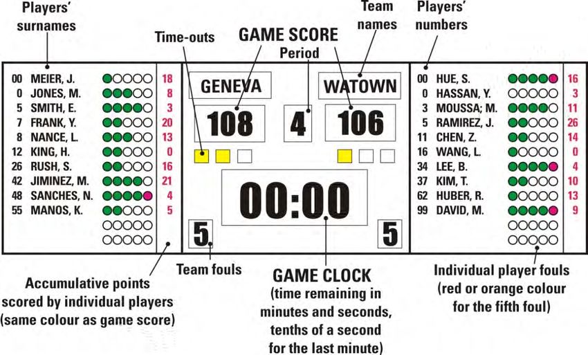
9.3 The scoreboard shall include and/or indicate:
• The digital countdown game clock.
• The points scored by each team, and for Level 1 the cumulative points scored by
each individual player.
• For Levels 1 and 2 the number of each individual player number (in the order 00, 0, 1,
2, 3, 4, 5, 6, 7, 8, 9, 10 and 11-99), and for Level 1 also their corresponding surnames.
There shall be a minimum of 12 digits to display each player’s surname.
• The team’s names. There shall be a minimum of 3 digits to display each team’s name.
• The number of fouls committed by each player on the team from 1 to 5. The fifth foul
shall be indicated in red or orange. The number may be shown with 5 indicators or
a number display with a minimum height of 135 mm. In addition, the 5th foul may be
indicated with a slow flashing display (~ 1 Hz) for 5 seconds.
• The number of team fouls from 1 to 5, stopping at 5.
• The number of the quarter from 1 to 4, and E for an overtime.
• The number of charged time-outs per half from 0 to 3.
• A clock for timing the time-out (optional). The game clock must not be used for this
purpose.
9.4 For Level 1 (obligatory) and Level 2 (recommended):
• The display on the scoreboard shall be in bright contrasting colours.
• The background of the display shall be antiglare.
• The digits used for displaying the numbers on the game clock and game score shall
be a minimum height of 300 mm (Level 1) or 250 mm (Level 2) and a minimum width
of 150 mm (Level 1) or 125 mm (Level 2). These digit sizes are obligatory for Level 2.
• The digits and characters used for displaying the numbers of the team fouls and
quarters or overtime shall be a minimum height of 250 mm and a minimum width of
125 mm.
• The digits and characters used for displaying the team names, players’ surnames
and numbers, and points scored by players shall be a minimum height of 150 mm.
• The scoreboard game clock, game scores and the shot clocks shall have a minimum
viewing angle of 130°.
9.5 The scoreboard shall:
• Not have any sharp edges or burrs.
• Be mounted securely.
June 2018 OFFICIAL BASKETBALL RULES 2018 Page 13 of 26• Be able to withstand severe impact from any ball according to DIN 18032-3.
• Have specific protection, if necessary, which shall not impair the readability of the
scoreboard.
• Have electromagnetic compatibility in accordance with the statutory requirements
of the respective country.
Diagram 9 Scoreboard for Level 1 (example of the layout)
10 Shot clock
10.1 The shot clock shall have:
• A separate control unit provided for the shot clock operator, with a very loud
automatic signal to indicate the end of the shot clock period when the display shows
zero (0).
• A display unit with a digital countdown, indicating the time in seconds only.
10.2 For Levels 1 and 2, the shot clock shall:
• Have the signal sounding for the end of the shot clock period when the display
shows zero (0.0).
• Indicate the time remaining in seconds; and tenths (1/10) of a second only during
the last 5 seconds of the shot clock period.
10.3 The shot clock shall have the ability to be:
• Started from 24 seconds.
• Started from 14 seconds.
• Stopped with the display indicating the time remaining.
• Restarted from the time at which it was stopped.
• Showing no display, if necessary.
10.4 For Levels 1 and 2 the shot clock shall be connected to the game clock so that when:
• The game clock stops, the shot clock shall also stop.
• The game clock starts, it is possible to start the shot clock manually.
• The shot clock stops and sounds, the game clock count continues and may be
stopped, if necessary, manually.
10.5 For Levels 1 and 2 the shot clock display unit (Diagram 10), together with a duplicate
game clock shall:
Page 14 of 26 OFFICIAL BASKETBALL RULES 2018 June 2018• Be mounted on each backboard support structure a minimum of 300 mm above and
behind the backboard (Diagram 1 or 2) or hung from the ceiling.
• Have the numbers of the shot clock in red colour and the numbers of the duplicate
game clock in yellow colour.
• Have the numbers of the shot clock display a minimum height of 230 mm and be
larger than the numbers of the duplicate game clock.
• For Level 1, have 3 or 4 display surfaces per unit or two units with double sided
surface (recommended for Level 2 and 3) to be clearly visible to everyone involved
in the game, including the spectators.
• Have the maximum weight of 60 kg, including the support structure.
• Be equipped with lighting around its perimeter (optional), which lights up in red only
when the game clock signal sounds for the end of a quarter or overtime.
• Be equipped with lighting along its perimeter at the top (optional), which lights up in
yellow only when the shot clock signal sounds and be mounted directly below the
red lighting for the game clock.
• Pass the test of protection against damage by balls according to DIN 18032-3 (see
References [9]).
• Have electromagnetic compatibility in accordance with the statutory requirements
of the respective country.
Diagram 10 Shot clock display unit and duplicate game clock, for Levels 1 and 2
(example of the layout)
11 Signals
11.1 There shall be at least 2 separate sound signals, with distinctly different and very loud
sounds:
• One provided for the timer and the scorer which shall sound automatically to
indicate the end of the playing time for a quarter or overtime. The timer and scorer
shall be able to sound the signal manually when appropriate to attract the attention
of the officials.
• One provided for the shot clock operator which shall sound automatically to indicate
the end of the shot clock period.
11.2 Both signals shall be sufficiently powerful to be easily heard above the most adverse or
noisy conditions. The sound volume shall have the ability to be adapted according to the
size of the sport hall and the noise of the crowd, to a maximum sound pressure level of
June 2018 OFFICIAL BASKETBALL RULES 2018 Page 15 of 26120 dBA measured at a distance of 1 m from the source of the sound. A connection to
the public information system of the sports hall is strongly recommended.
12 Player foul markers
The 5 player foul markers provided for the scorer shall be:
• Of white colour.
• With numbers a minimum of 200 mm in length and 100 mm in width.
• Numbered from 1 to 5 (1 to 4 in black and the number 5 in red).
13 Team foul markers
13.1 The 2 team foul markers provided for the scorer shall be:
• Of red colour.
• A minimum of 350 mm in height and of 200 mm in width.
• Clearly visible to everyone involved in the game, including the spectators, when
positioned on either side of the scorer’s table.
• Used to indicate the number of team fouls up to 5 and to show that a team has
reached the team foul situation.
13.2 Electrical or electronic devices may be used but they shall meet the above specifi-
cations.
14 Alternating possession arrow
The alternating possession arrow device (Diagram 11) provided for the scorer shall:
• Have an arrow of a minimum length of 100 mm and height 100 mm.
• Display on the front side an arrow, illuminated in bright red colour when switched
on, showing the direction of the alternating possession.
• Be positioned in the centre of the scorer’s table and shall be clearly visible to
everyone involved in the game, including the spectators.
Diagram 11 Alternating possession arrow (Example of the layout)
15 Playing floor
15.1 The playing floor surface shall be made of:
• Permanent wooden flooring (Levels 1 and 2).
• Mobile wooden flooring (Levels 1 and 2).
• Permanent synthetic flooring (Levels 2 and 3).
• Mobile synthetic flooring (Levels 2 and 3).
15.2 The playing floor shall:
• Be a minimum length of 32,000 mm and a minimum width of 19,000 mm.
• Have an antiglare surface.
15.3 For Level 1, permanent wooden flooring, the following requirements are valid:
• Sports functional requirements
▬ Force reduction (Shock absorption) according to
EN 14808: min. 50 %
Page 16 of 26 OFFICIAL BASKETBALL RULES 2018 June 2018▬ Vertical deformation according to EN 14809: min. 2.3 mm, max. 5.0 mm
▬ Vertical ball behaviour according to EN 12235
(basketball): min. 93 %
▬ Sliding properties according to prEN 14903: min. 0.4, max. 0.7
or according to EN 13036-4 (dry condition): min. 80, max. 110
The requirements for the above properties have to
be fulfilled at each system testing spot
▬ Area deflection according to DIN V 18032-2 average per direction:
(2001-04): max. 20 %;
single values up to 30 %
• Requirements regarding uniformity
▬ Force Reduction ± 5 % (absolute) from the average
▬ Vertical Deformation ± 0.7 mm from the average
▬ Vertical ball behaviour ± 3 % (absolute) from the average
15.4 For Level 1, mobile wooden flooring, the following requirements are valid:
• Sports functional requirements
▬ Force reduction (Shock absorption) according to
EN 14808: min. 40 %
▬ Vertical deformation according to EN 14809: min. 1.5 mm, max. 5.0 mm
▬ Vertical ball behaviour according to EN 12235
(basketball): min. 93 %
▬ Sliding properties according to prEN 14903: min. 0.4, max. 0.7
or according to EN 13036-4 (dry condition): min. 80, max. 110
The requirements for the above properties have to
be fulfilled at each system testing spot
• Requirements regarding uniformity
▬ Force Reduction ± 5 % (absolute) from the average
▬ Vertical Deformation ± 0.7 mm from the average
▬ Vertical ball behaviour ± 3 % (absolute) from the average
15.5 For Levels 2 and 3, permanent synthetic flooring, the following requirements are valid:
• Sports functional requirements
▬ Force reduction (Shock absorption) according to
EN 14808: min. 25 %
▬ Vertical deformation according to EN 14809: max. 3.5 mm
▬ Vertical ball behaviour according to EN 12235
(basketball): min. 90 %
▬ Sliding properties according to prEN 14903: min. 80, max. 110
The requirements for the above properties have to
be fulfilled at each system testing spot
15.6 The manufacturer, together with the flooring installation company, shall be obliged to
produce documentation for each customer comprising of at least the following: Results
of the prototype test, a description of the installation procedure, maintenance advice,
results of the inspection and approval of the existing installation carried out by approved
inspection officials.
15.7 The playing floor must have the ability to carry mobile or floor-fixed backboard support
structures without degrading the characteristics of the backboard support structure.
Conversely, the mobile backboard support structures must be constructed in such a way
June 2018 OFFICIAL BASKETBALL RULES 2018 Page 17 of 26that their weight is spread over a bigger contact area, thus eliminating the risk for
damage to the floor, both in game position and during transportation on the playing court.
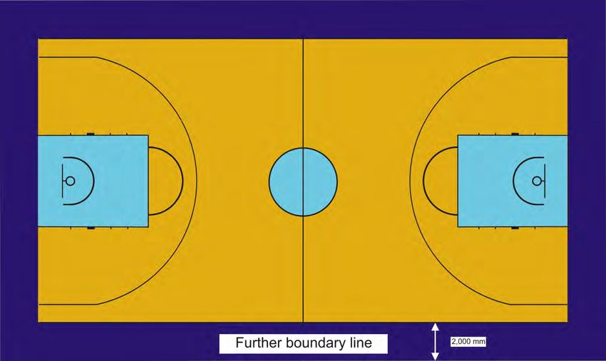
16 Playing court
16.1 The playing court shall be marked by:
• 50 mm lines, as per the Official Basketball Rules.
• A further boundary line (Diagram 12), in a sharply contrasting colour and having a
minimum width of 2,000 mm.
16.2 The scorer’s table, a minimum of 6,000 mm in length and 800 mm in height, must be placed
on a platform of a minimum of 200 mm in height.
16.3 All spectators must be seated at a distance of at least 2,000 mm from the outer edge of
the boundary line of the playing court.
16.4 The height of the ceiling or the lowest obstruction above the playing floor shall be a
minimum of 7 m.
Diagram 12 Playing court
17 Lighting
17.1 The vertical illuminance (EC) (illuminance towards the main camera) and (EV) (illumi-
nance towards the mobile cameras) are a key parameter for the picture quality. If there
are varying levels of vertical illuminance at different positions on the playing court, then
it can be disturbing when panning the camera. It is therefore essential that there is total
uniformity in the distribution of the vertical illuminance over the entire playing court (also
called uniformity of the vertical illuminance).
The vertical illuminance shall be kept as constant as possible in the four main directions
facing the sides of the playing court where the cameras are generally located.
The horizontal illuminance (EH) is the quantity of light falling on the playing court. As the
illuminated playing court is the principal part of the camera’s field of view, the horizontal
illuminance shall be as uniform as possible and the ratio between the average horizontal
illuminance and the average vertical illuminance towards the main camera shall be kept
to a level that ensures a good quality contrast of the pictures.
Page 18 of 26 OFFICIAL BASKETBALL RULES 2018 June 2018Main camera illuminance Vertical illuminance Horizontal illuminance
(EC) (EV) (EH)
17.2 Lighting requirements and recommendations
The venue lighting must be designed for television broadcasting while minimising the
glare for players and officials.
• Illuminance level
The playing court shall be uniformly and adequately lit. The lighting criteria descry-
bed above must be calculated and shall comply with the values given in the
following table.
Distinction shall be made between the playing court (19 m x 32 m) including the
further boundary line and the total playing area (22 m x 35 m) which includes a 1.5 m
wide area around the playing court (including the team benches).
Average values are maintained values.
The illuminance calculations and measurements shall take place on a 2 m x 2 m grid
point. Annex 1 shows the grid point to be used for the calculations and the typical
camera positions.
The vertical illuminance shall be calculated at any grid point, at 1.5 m above the
playing court in the direction of the main camera (EC) and for each of the 4 main
directions (X and Y) facing the sides of the playing court for the mobile cameras (EV).
UXY is the ratio between the minimum and the maximum values of EV calculated
over the four main directions.
No calculations are required for the Beauty Shot camera.
The horizontal illuminance (EH) is calculated at floor level.
• Glare towards the main camera
The reflections of bright light sources on the playing court can cause bright spots
which will affect the camera picture as illustrated below. Glare caused by high
intensity light bouncing off the highly reflective glossy playing court surfaces
towards the main camera position must be avoided especially on all playing court
lines.
June 2018 OFFICIAL BASKETBALL RULES 2018 Page 19 of 26Careful attention to the simple necessary geometry will often eliminate these
unwanted reflected images (see Annex 2).
• Glare
It is essential that there is no glare whatsoever that affects the view of the
basketball players when they are playing. The lighting positions and direction shall
be defined in such a way as to take account of the players’ view (See Annex 2). The
intensity of the light source must be adapted in relation to the installation height.
• Spectator areas
The average illuminance towards the main camera for the first 15 rows of seats shall
be between 10 % and 25 % of the average illuminance on the playing court; the
illuminance beyond the first 15 rows shall then uniformly reduce.
• Light source
The light sources shall have a colour rendering index of at least Ra 80 and the colour
temperature shall be between 4000 K and 6000 K. Television broadcasters require a
constant colour temperature and therefore the colour temperature must not deviate
from the average value by more than ± 500 K. The intensity of discharge lamps
(generally used in sports lighting applications) fluctuates if supplied with an
electromagnetic gear due to the 50 Hz or 60 Hz supply voltage frequency. This
phenomenon cannot be observed with the eye, but it is very visible in ultra-slow
motion imagery broadcasts of live sporting events taking place under artificial
lighting, as these cameras capture images at rates of speed much faster than the
lighting cycle rate, creating a flicker effect during slow motion replays.
From a production standpoint the above flicker effect is not acceptable and
therefore the lighting installation must be flicker-free. This is guaranteed if the
flicker factor at any point of the TPA is less than 1 %. New technologies such as
discharge lamps coupled with electronic gears, or LED lighting allow guaranteed
flicker-free lighting.
The full playing court lighting shall be turned on at least 90 minutes prior to the start
of the game and maintained until the prescribed requirements for pre-game warm-
ups and game play. It shall remain fully lit for at least 30 minutes after the game.
Spotlight introductions for the teams or special ceremonies and entertainment can
only be used if the lighting system has instant restrike capabilities which will not
alter the light source colour properties.
Page 20 of 26 OFFICIAL BASKETBALL RULES 2018 June 201817.3 Assessment (measurements and visual inspection)
A visual inspection shall be carried out to evaluate the lighting installation.
No reflected light shall be visible when standing at the main camera position. As TV
cameras are more sensitive than the human eye, this can be checked by taking pictures
with a digital camera. Attention shall be paid to floodlight illuminances wherever they
may be located. The players must not be dazzled especially when they are looking at the
baskets.
Main lighting criteria measurements (to be taken)
Lighting measurement of the vertical illuminance (EC) towards the main camera and EV
towards the mobile cameras (4 main directions ± X and ± Y) over the total playing area
shall be carried out at a height of 1.5 m above the playing court at any grid point
according to annex 1.
Main camera illuminance Vertical illuminance Horizontal illuminance
(EC) measurement (EV) measurement (EH) measurement
The horizontal illuminance (EH) shall be carried out on the same grid point but at floor
level.
Whenever possible the colour rendering index and colour temperature shall be
measured using a spectrophotometer at the centre of the playing court and at each free-
throw line.
The flicker factor shall be measured using a flicker meter at any grid point towards the
4 main directions at a height of 1.5 m. The measurement shall be carried out every 4
metres using every other point of the grid point shown in annex 1.
Flicker factor measurement
June 2018 OFFICIAL BASKETBALL RULES 2018 Page 21 of 26Annex 1 Grid Point for calculations and typical camera position
Annex 2 Recommendation for lighting positions
The location of the floodlights is critical to comply with the lighting requirements. It must
ensure that the lighting requirements can be achieved, while not interfering with the
players’ visibility as well as not creating any glare towards the main camera.
Freedom shall be given to the lighting designer to position the floodlights to provide the
best technical solution. It is highly recommended to have a lighting specialist involved in
the project from the initial stage.
When the main camera position has been determined, the sources of glare can be
minimised by avoiding the installation of floodlights in the forbidden area as shown in
the figure below.
Page 22 of 26 OFFICIAL BASKETBALL RULES 2018 June 2018Forbidden area for lighting mountings to avoid glare towards the main camera
The lighting aiming angle (measured from downward
vertical) shall ideally be ≤ 60° in order to minimise the
glare to the players.
Careful attention shall be paid to the floodlight positioning with regards to their aiming
directions which shall not interfere with the players vision, especially when they are
shooting at the baskets.
The following example illustrates a critical location for floodlights. In this example, the
floodlights located in the 20° area shall not be aimed directly towards any player in a
shooting position.
June 2018 OFFICIAL BASKETBALL RULES 2018 Page 23 of 2618 Advertising boards
18.1 Advertising boards may be located around the playing court and:
• Shall be located at a minimum distance of 2,000 mm from the endlines and sidelines.
They may be located on all sides around the playing court (Diagram 12 and 13).
• Those along the endlines shall have a minimum gap of 900 mm on each side of the
mobile backstop units so that the floor wiper(s) and portable TV camera(s) can pass
through, if necessary.
• Those along the table site shall have a minimum gap of 2,000 mm on each side of the
scorer’s table for the players, substitutes and coaches to pass through (Diagram
13).
• For televised games they shall be located along the sidelines opposite the location
of the main camera.
• Are permitted in front of the scorer's table provided that they are placed directly in
front of and horizontally and vertically flush with the table.
18.2 Advertising boards shall:
• Not exceed a height of 1,000 mm from the playing court.
• Be padded around the top and on the side edges with a minimum thickness of
20 mm.
• Have no burrs and all edges shall be rounded off.
• Be in accordance with the national safety requirements for electrical equipment in
the respective country.
• Have mechanical protection for all engine driven parts.
• Be non-flammable.
Diagram 13 Advertising boards – main camera table side
Page 24 of 26 OFFICIAL BASKETBALL RULES 2018 June 2018Diagram 14 Advertising boards – main camera opposite side
19 Spectator areas
19.1 The spectator areas shall:
• Allow the free movement of the public, including persons with a disability.
• Enable spectators to have a comfortable view of the event.
• Have unobstructed lines of visibility from all seats, as shown in Diagram 15, unless
the local standards allow for deviations.
h = 800 mm a•b
d > 100 mm x=
c−d
Diagram 15 Spectators' line of visibility
June 2018 OFFICIAL BASKETBALL RULES 2018 Page 25 of 2619.2 The seating capacity is defined as follows, unless the local standards allow for
deviations:
• The total capacity of the sports hall is the total number of both the seated and
standing positions.
• The number of seated positions is the total number of seats or the total length of the
terraces or benches in metres, divided by 480 mm.
• The number of standing positions is the assigned floor space, with 35 spectators for
every 10 m2.
The above specifications are recommendations only.
20 References
[1] DIN ISO 286, 1990: ISO system of limits and fits; bases of tolerances, deviations and fits
[2] National Colour System of Standardiseringkommissionen i Sverige (SIS), Doc. No. SS019102
[3] EN 913, Annex C, 1996: Determination of shock absorption of padding
[4] EN 71-3, 1995: Safety of toys. Specification for migration of certain elements
[5] EN 1270, 1998: Playing field equipment – Basketball equipment – Functional and safety
requirements, test methods
[6] FIBA Television Manual, Edition March 2015
[7] EN 14904, 2006: Surfaces for sports areas – Indoor surfaces for multi-sports use –
Specification.
[8] DIN 18032-2, 2001: Sport Hall surfaces, requirements, testing, maintenance
[9] DIN 18032-3, 1997: Sport halls: halls for gymnastic and games: testing of safety against ball
throwing
[10] ISO 9002, 1994: Quality assurance management
[11] Floors for Indoor Sports, Design Guidance Note, Sport England, September 2007, Rev. 002
ISO standards are sold by the ISO General Secretary in Geneva, Switzerland:
ISO Sales
Case Postale 56
1211 Genève 20
SUISSE
E-mail: sales@isocs.iso.ch
Standards from the European Committee for Standardisation (CEN) and national standards are
available directly from the national standards bodies.
Page 26 of 26 OFFICIAL BASKETBALL RULES 2018 June 2018You can also read