OIL AND GAS IN PENNSYLVANIA - Educational Series 8
←
→
Page content transcription
If your browser does not render page correctly, please read the page content below
Educational Series 8

   OIL AND GAS IN
    PENNSYLVANIA

  COMMONWEALTH OF PENNSYLVANIA
          DEPARTMENT OF
CONSERVATION AND NATURAL RESOURCES
            BUREAU OF
 TOPOGRAPHIC AND GEOLOGIC SURVEY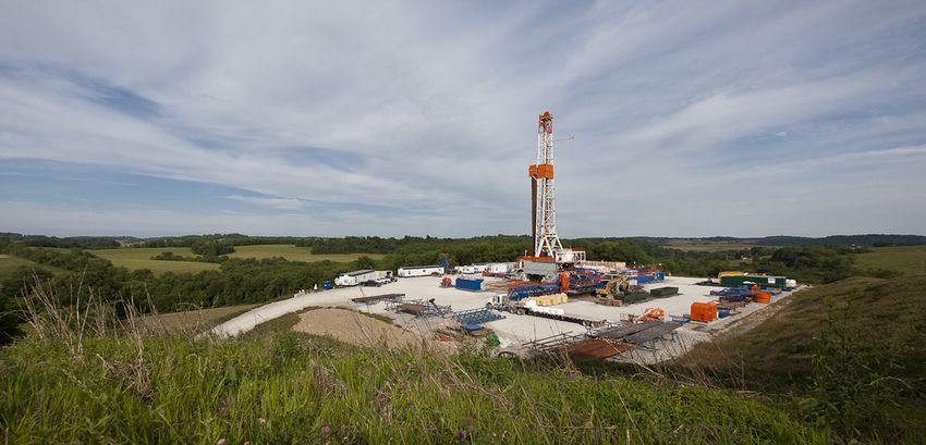
COMMONWEALTH OF PENNSYLVANIA
Tom Corbett, Governor
DEPARTMENT OF
CONSERVATION AND NATURAL RESOURCES
Ellen Ferretti, Secretary
OFFICE OF CONSERVATION AND TECHNICAL SERVICES
Nathan Flood, Deputy Secretary
BUREAU OF TOPOGRAPHIC AND GEOLOGIC SURVEY
George E. W. Love, Director
FRONT COVER: Improvements in directional drilling and
hydraulic fracturing have helped to make it economically de-
sirable to produce oil and gas from deeper formations. Now
shale gas fields are being developed at great depths across
much of Pennsylvania, even within areas already producing
from shallow reservoirs. The sketch (not to scale) illustrates
a modern rig (left) drilling to a shale layer, which is far below
the rock units shown. On a nearby hill, a pump jack produces
oil from a shallow structural trap.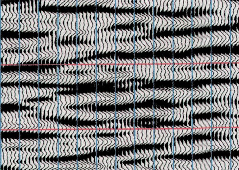
Educational Series 8

Oil and Gas in
Pennsylvania

                   by Kathy J. Flaherty
                      ABARTA Energy
                      and Thomas Flaherty, III
                      Pennsylvania Department of
                      Environmental Protection

PENNSYLVANIA GEOLOGICAL SURVEY
FOURTH SERIES
HARRISBURG

2014
When reproducing material from this book, please cite the source
as follows:
Flaherty, K. J., and Flaherty, Thomas, III, 2014, Oil and
gas in Pennsylvania (3rd ed.): Pennsylvania Geological Sur
vey, 4th ser., Educational Series 8, 36 p.
Pennsylvania
Department of Conservation and Natural Resources
dcnr.state.pa.us
Bureau of Topographic and Geologic Survey
dcnr.state.pa.us/topogeo
Illustrations drafted by
James H. Dolimpio and Caron E. O'Neil
First Edition, January 1969
Second Edition, May 2002
Third Edition, June 2014Table of Contents
Page
Welcome to the oil and gas patch!. . . . . . . . . . . . . . . . . . . . . 1
What is petroleum?. . . . . . . . . . . . . . . . . . . . . . . . . . . . . . . . 2
How does petroleum form?. . . . . . . . . . . . . . . . . . . . . . . . . . 3
Finding petroleum. . . . . . . . . . . . . . . . . . . . . . . . . . . . . . . . . 5
Drilling for oil and gas . . . . . . . . . . . . . . . . . . . . . . . . . . . . . 10
Logging the well. . . . . . . . . . . . . . . . . . . . . . . . . . . . . . . . . . 15
Producing the well . . . . . . . . . . . . . . . . . . . . . . . . . . . . . . . . 17
Refining oil . . . . . . . . . . . . . . . . . . . . . . . . . . . . . . . . . . . . . 20
Developing an oil or gas field. . . . . . . . . . . . . . . . . . . . . . . . . 22
Underground natural gas storage . . . . . . . . . . . . . . . . . . . . . . 26
What happens when the well runs dry?. . . . . . . . . . . . . . . . . . 28
The future of oil and gas. . . . . . . . . . . . . . . . . . . . . . . . . . . . 28
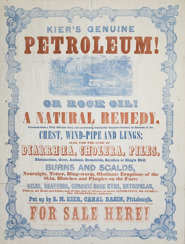
Looking back: how it all began . . . . . . . . . . . . . . . . . . . . . . . 30
Influence of the petroleum industry on other industries. . . . . . . 33
Additional reading. . . . . . . . . . . . . . . . . . . . . . . . . . . . . . . . . 35
Places to visit. . . . . . . . . . . . . . . . . . . . . . . . . . . . . . . . . . . . 36
Acknowledgments. . . . . . . . . . . . . . . . . . . . . . . . . . . . . . . . . 36
iiiHi! I’m Spud.
“Spud” is a word used
SPUD
by oil and gas drillers. It
means “to begin to drill a
well.” I’ll be taking you on a
tour of the oil and gas, or petro
leum, industry. We’ll look at many
aspects of oil and gas, such as how
it is found and produced, and how it
is used.
Turn to the back cover of this book
let. Take a few minutes to look at the chart,
which shows the kinds of rocks that lie under
ground in western Pennsylvania. The symbols for
the different rock types are also used in other figures
in this booklet. This figure will be a handy reference
as you read about oil and gas in Pennsylvania. Let’s get
started!
ivOIL AND GAS IN PENNSYLVANIA
by Kathy J. Flaherty1 and Thomas Flaherty, III2
WELCOME TO THE OIL AND GAS PATCH!
Think fast! Paint, acrylic carpets, and deodorant have something
in common. Do you know what it is? Suppose we add gasoline and
WD–40 to the list? Got it now? They are all by-products of oil and gas,
or petroleum. You may not realize just how much your life is affected
by petroleum.
Let’s take an example from part of your typical day. You woke
up this morning and stepped onto the acrylic carpet. You reached for
your eyeglasses and toothpaste tube, then headed down the freshly
painted hallway. You popped a CD into your stereo to sing along with
as you closed the shower curtain and reached for a plastic bottle of
shampoo. After a refreshing shower of hot water brought to you through
plastic water pipes, you applied your deodorant, a dab of perfume
or aftershave, and dressed in synthetic running shoes and a sweater.
You used a hair dryer, comb, brush, and lip balm, and headed for
the kitchen. You put your sandwich in plastic wrap and some soup in
a thermos bottle. You pulled up a vinyl chair to the Plexiglas® table,
ate your breakfast, and sipped orange juice from a plastic cup. On your
way out the door, you swished your dishes in dishwash-
PU
ing liquid and unwrapped a piece of bubble gum. You
S
D
put your pen and tennis racket in your backpack and
grabbed your boots, umbrella, and waxed-paper-bag
lunch. After placing a quick telephone call, you
OIL
started your car or jumped onto the bus, all
set for the day, thanks to petroleum!
Oil goes into nearly everything. It is a key
ingredient in a wide variety of products
essential to modern everyday life. Look
around your home, school, or office, and
try to imagine life without the benefits of
petroleum.
1
ABARTA Energy, 200 Alpha Drive, Pittsburgh, PA 15238.
2
Pennsylvania Department of Environmental Protection, Bureau of Oil and Gas
Management, 400 Waterfront Drive, Pittsburgh, PA 15222.
12 OIL AND GAS IN PENNSYLVANIA
WHAT IS PETROLEUM?
So what is this substance called petroleum that seems to be every
where in our daily lives? To answer that question, we need to start at
the beginning. The basic building blocks of the world are tiny particles
known as atoms. Everything is made of atoms. Each atom has a
nucleus that is surrounded by at least one electron. The number and
arrangement of the electrons around the nucleus are different for each
element. Clusters of two or more atoms are called molecules. The
elements hydrogen and oxygen, for example, combine to form water
molecules. Petroleum molecules are made mostly of the elements hydro
gen and carbon. Hydrogen and carbon can combine in many different
ways to form these hydrocarbon molecules, which vary greatly in
size and shape. Carbon atoms can connect with up to four other
atoms, and hydrogen atoms can connect to only one. Therefore, hydro
carbons usually form as carbon chains surrounded by hydrogen atoms.
Hydrocarbons make up petroleum, which occurs naturally. Petro
leum is found in two forms: oil, commonly called crude oil, and gas,
commonly referred to as natural gas. Typical crude oil consists of 85
percent (by weight) carbon, 13 percent hydrogen, 1 percent sulfur, 0.5
percent nitrogen, and 0.5 percent oxygen. Natural gas may consist of
75 percent carbon, 20 percent hydrogen, 0.1 percent sulfur, and 4.9
percent nitrogen. However, crude oil or natural gas from different loca
tions are never exactly the same.
H H H H H H H H H
-
-
-
-
-
-
-
-
-
C- C - C - C - C - C- H
H
H H- C - C - C -
-
-
-
-
-
-
-
-
H H H H H H H H
-
-
H
Me tha ne Oc tan e
(na tur al ga s) (ga sol ine ) UD
Here a hydrocarbon molecule, there a hydrocarbon
molecule. Slight differences in organization result
in totally different substances.HOW DOES PETROLEUM FORM? 3
HOW DOES PETROLEUM FORM?
Variability in the composition of petroleum is related to how it was
formed. Geologists believe that petroleum is produced from organic
matter found in rocks.
Many sedimentary rocks contain organic matter formed from the
remains of dead plants and animals. Most of the rocks under Pennsyl
vania are sedimentary rocks. The climate at the time these rocks were
formed was very different than it is today. The air was warm, and a
shallow sea covered much of the region in an elongated basin (the
Appalachian basin) that stretched from Newfoundland to Alabama.
Mountains bordered the east side of the basin (east of Pennsylvania).
Plankton, fish, corals, marine plants, algae, and shellfish were abun
dant in the sea. At times, evaporation caused portions of the sea to
dry up, leaving shallow, isolated ponds. Plants grew on the land sur
face between the ponds.
The mountains eroded very slowly. Streams flowing toward the
sea carried grains, pebbles, and gravel broken away from the eroding
mountains. These were deposited and became sandbars, beaches, and
soil. They were then covered with more and more material eroding
from the mountains.
Meanwhile, plants dropped leaves and branches onto the land and
into the sea. They were covered with sand and gravel. Dead creatures
and masses of dead algae and plankton sank to the muddy bottoms
of the ponds and sea, and were slowly buried and pressed down by
more layers of mud, sand, and gravel. The muddy bottoms of the
ponds and sea hardened and became shale. Grains, gravel, and pebble
layers hardened into sandstone and conglomerate.
Living things became organic debris
that accumulated over time.
Algae and plankton
Sand
Older rock
Mud4 OIL AND GAS IN PENNSYLVANIA
The accumulating organic materials were
covered with mud, sand, and gravel, and
still more organic material.
Algae and plankton
Sand
Organic matter mixed
with mud and some sand
Organic ooze
Older rock
Mud
The muddy organic layer was compressed
and hardened to form shale.
Algae and plankton
New layer of organic
mud and ooze
Organic-rich shale
Older rock
You see now that various processes form sedimentary rocks, includ
ing the deposition of sediments that have been moved from other places
by wind or water. Chemistry plays a role in the decaying of plants and
animals. Some sedimentary rocks, such as shale and limestone, may
contain abundant organic material—the hydrogen and carbon that will
become petroleum. Petroleum-rich rocks are called source rocks, and
they occur at various depths below the earth’s surface.
When a source rock is buried beneath the earth’s surface, the
organic material is subjected to heat and pressure. These forces transFINDING PETROLEUM 5
form the organic material into hydrocarbon. The chemical composi
tion of the hydrocarbon depends on several factors: the nature of the
original organic material, the amount of pressure (deeper burial means
higher pressure), the temperature (deeper burial means higher tem
perature), and the length of time the rock is buried (usually measured
in millions of years).
Hot
Want to cook up some petro- Stuff!
leum? The recipe is simple: just
combine a few tons of organic
matter, add a few thousand
pounds per square inch of pres-
sure, and set temperatures be- UD
tween 140°F and 320°F for a few
million years to make oil. Natu- Pressure
ral gas requires a slightly higher OIL
temperature: 212°F to 392°F. Organic matter
FINDING PETROLEUM
Where do you find oil and gas?
Petroleum (both oil and gas) may remain within the source rock
in which it forms, or if there is a pathway, it may migrate upward and
accumulate in places that have lower pressures and temperatures. Any
rock that holds petroleum is referred to as a reservoir. Reservoirs in
clude both source rocks and rocks that contain migrated petroleum. In
the nineteenth and twentieth centuries, most production was from res
ervoir rocks, such as sandstones, that were not source rocks. Because of
advances in drilling techniques and the rising cost of petroleum, drillers
now produce a lot of petroleum from targeted zones within the source
reservoir rocks themselves. Throughout the history of Pennsylvania’s oil
and gas industry, geologists have looked for certain physical character
istics that make some reservoirs or zones within reservoirs preferred
targets for oil and gas production.
Open spaces in a rock are called pores. Rocks having lots of pore
space are high in porosity—an important characteristic of conven
tional oil and gas reservoirs. A reservoir having high porosity can hold
a greater amount of petroleum. Porosity can be high if the rock grains
do not fit together perfectly; it can also be high because of openings
that are formed either when a rock is fractured or cracked, or when6 OIL AND GAS IN PENNSYLVANIA
minerals in the cement holding the grains together are dissolved. In
Pennsylvania, the porosity of oil and gas reservoir rocks ranges from
nearly none at all to more than 50 percent. Typical sandstone reser
voirs average 12 percent porosity. This means that 12 percent of the
rock is open pore space.
The ease with which petroleum
moves from one pore space to an
other is called permeability and is
determined by the size of the open SP
UD
ings that connect the pores. If per
meability is high, petroleum has the
ability to move relatively easily. If
permeability is low, petroleum may
not be able to flow through the rock
In this permeable rock, Spud
at all. As you will soon learn, drillers has no difficulty moving be-
have a way to increase permeability tween pore spaces.
in rocks, which many times can be
used to overcome this problem. High permeability is desirable in a
petroleum reservoir because petroleum that can move through a rock
is easier to remove. Impermeable rocks, or those with little or no
communication between pore spaces, serve as good cap rocks to seal
the petroleum within the reservoir. Cap rocks function much like caps
on bottles. Rocks with low permeability, such as some shale and lime
stone layers, make great cap rocks.
In a rock having a mixture of grain
sizes, smaller grains can clog the
pores between larger grains. This is
one of many ways a rock can have
low porosity and low permeability.
In a rock having similar-sized grains,
the pores between the grains can
be open but unconnected. This is
one way a rock can have high po-
rosity and low permeability.FINDING PETROLEUM 7
There is nothing like a good trap!
Oil and gas migrates until it becomes blocked by a cap rock. Be
cause it cannot move any farther, it becomes trapped. Two common
types of traps are structural traps and stratigraphic traps. In
Pennsylvania, petroleum is found in both types of traps.
A geologic structure is formed when rock layers become folded
(bent) or faulted (broken) by pressure from shifting landmasses. Struc
tural traps occur where a rock holding oil or gas is isolated from other
porous and permeable rocks by folds or faults that prevent the petro
leum from escaping. Looking for oil and gas means looking for the
kinds of structures that may trap it. Understanding how geological
structures are formed and where they can be found is important to
petroleum exploration.
This structural trap, shaped like an S PUD
arch, is called an anticline. In it, a
permeable sandstone is sandwiched
between two impermeable rock lay-
ers, so that petroleum in the
sandstone cannot escape.
The hydrocarbons migrate
upward through the sand-
stone and separate out: gas
rises to the top, and oil
(where it occurs) stays below
the gas. Any water that was
present in the sandstone is
displaced below the oil and
gas.
Stratigraphy is the study of strata, or layers of rock. Sediment,
such as sand and small stones, and organic matter are deposited in
layers, or beds. Variations in the type of materials, as well as processes
such as cementation that hardens the sediment to rock, result in beds
of rock that change character both laterally and vertically. Even slight
changes in the characteristics of a rock can be enough of a barrier to
cause it to behave like a trap to the migrating petroleum. A stratigraphic
trap occurs where oil and gas collects in a more porous rock, like sand
stone, and is sandwiched in place by less permeable rock layers. Of
course, it is possible in nature to have a combination trap, which is
a mixture of the features from both structural and stratigraphic traps.8 OIL AND GAS IN PENNSYLVANIA
S PUD
This stratigraphic
trap holds petro-
leum within a po-
rous rock that is
surrounded by less
porous and less
permeable rocks.
Why is it important to know all of this? Petroleum occurs beneath
the earth’s surface at depths ranging from a few tens of feet to several
miles. We obtain that petroleum by drilling a hole through the rocks
until a reservoir is encountered. Therefore, it makes sense to have a
good idea about where petroleum reservoir rocks may be found before
starting to drill.
Let’s go on a hunt!
We know that petroleum is trapped within a reservoir, and therefore
the search for petroleum involves using subsurface information to find
it. This process is known to geologists as prospecting. Much modern
petroleum prospecting is done using digital data and computers. This
usually means combining art with science. To be a good prospector, it
is necessary to think in terms of three-dimensional space. The idea is
to imagine and build a three-dimensional picture or model that shows
the lateral and vertical dimensions of the target. Then the prospector
can figure out where to begin drilling on the surface in order to inter
sect the reservoir rock.
Geologists construct mod
els to help understand
earth processes, such as
NK
RO
the formation of this fold
G
SK
and fault. A simple three-
dimensional sketch or SPU D
computer model usually
serves the purpose quite
nicely.FINDING PETROLEUM 9
To create a three-dimensional image of a petroleum target, a geolo
gist needs information. This information comes from many sources. First,
the rocks on the earth’s surface are studied. If there are existing holes
drilled in the prospect area, rock cutting samples and other informa
tion from these holes are studied. In areas where no wells have been
drilled, subsurface data can be obtained by a remote-sensing process
such as seismic reflection. In seismic reflection, a large number of
sensors are placed on the ground near a noise-making device. Some
times the device is an in-ground explosive, and sometimes it is a large
truck, called a “thumper truck,” that has a vibrator attached. When all
of the sensors are lined up or spread out in a gridlike network, work
ers generate the noise. Sound waves created by the noise travel down
ward and horizontally. As the sound waves travel, they encounter
different types of rocks and are reflected back to the surface, where
they are “heard” by the sensors. Different rock types reflect the waves
differently. Some rocks, such as limestone, return a strong signal. The
sensors record this information, and a sketch that represents the way
the rocks are lying deep below the surface of the earth can be created.
Interpretations of the recorded data enable geologists to learn more
about the rocks that are too deep to be seen.
Seismic sound waves re-
flected off of subsurface
rock layers are recorded
by surface sensors. The
recordings are plotted, as
shown here, and used by
scientists to help interpret
rock types and structures
occurring at depth.
Geologists also use two-dimensional drawings to help visualize their
targets. They might begin with a cross section, or side view, through
the oil- and gas-bearing rocks. A cross section shows changes in rock
type, orientation, and thickness in a given direction. Next, a geologist
might draw an isopach map, which consists of contour lines show
ing the thickness of the source rock or reservoir. This may be impor
tant because the thicker the target rock, the more petroleum it may
hold. Finally, a geologist might employ a structure map, which shows10 OIL AND GAS IN PENNSYLVANIA
contour lines on the surface of a rock layer, to illustrate how the rocks
have been folded, faulted, or otherwise distorted underground. Geolo
gists can use structure maps to target the higher portions of a fold or
the side of a faulted sequence of rocks where oil and natural gas has
accumulated. Just as importantly, structure maps may help geologists
avoid excessively faulted or fractured rocks from which oil or gas has
already escaped.
By using tools such as
isopach maps, cross sec
tions, structure maps, and
seismic or other remote-
sensing data, a geologist
constructs a complete view
2 Miles or model of the geometry
SP
and characteristics of the
rocks before drilling. The
UD Gas well
Show of
gas
Dry hole
model helps the geologist
to determine where to drill
a well. The goal is to find
Spud uses a cross-section diagram to the most prospective oil
select a good spot in the thickest part
of a petroleum reservoir to drill a new and gas target, which may
well. be where the reservoir rock
is thickest, most porous and
permeable, or influenced by
a stratigraphic or structural
S trap.
0'
15' 10'
0'
2
x 0'
5' “X” marks the spot! An
9' isopach map shows where
1' a reservoir rock is thick-
est, and therefore where
Mapping
Geolog
it may be the most pro-
y of
Pennsylva
nia
Oil
ductive.
DRILLING FOR OIL AND GAS
Let’s drill here!
Once the geologist has determined the best location on the sur
face for a well, and after leasing the mineral rights, the next step is to
plan for and obtain a permit to drill the well. In Pennsylvania, the De
partment of Environmental Protection, Bureau of Oil and Gas ManageDRILLING FOR OIL AND GAS 11
!
DLIFE! ERE D NO
RARE WIL NG! ER H EN RILLI
NO DRILLI O DANG PLACE DAN NG
N AT
GRE DRILL! PLA GER !
TO NTS ED
!
!
STREAM G!
LIN
NO DRIL
Sometimes it is a challenge to find an environmentally acceptable
drill site in a geologically favorable area. It is the job of the well
operator to conduct business in a responsible way with as little
environmental disturbance as possible.
ment, issues such permits. To qualify for a permit, the well must be
planned in an environmentally responsible manner. It may be neces
sary to shift the exact position of the proposed well in order to accom
modate environmentally sensitive natural resources, such as streams
and wetlands, or endangered and protected wildlife areas.
The distance from other producing wells can also be a considera
tion; a driller does not want to position a new well too close to an exist
ing oil or gas well. Crowding might decrease the production of existing
wells. The placement of the access road that leads from a paved
highway to a proposed well location is another important factor. Care
must be taken to minimize its impact on the general public and the
surface landowner by avoiding government-owned lands, croplands,
and pastures as much as possible. Because construction of the access
road and well site usually involves moving considerable amounts of
earth around with a bulldozer, all plans should be designed to minimize
changes to an area’s natural erosion and sedimentation processes.
Modern shale well sites are designed to minimize impact to the
land. Many well operators plan their work in advance and build a well
pad meant to accommodate several wells, rather than a separate pad
site for each well. On a multi-well pad, the drilling rig can be moved
in multiple directions, and the vertical portion of each well might be
only 15 feet apart. A well is drilled vertically to about 1,000 feet above
the shale. Then the driller kicks off, or starts to angle the hole, land
ing it horizontally in the shale zone of interest. From here, the well will
be drilled several thousand more feet into the shale. The driller steers12 OIL AND GAS IN PENNSYLVANIA
SCALE
TOP VIEW 0 1,000 FT
Wellhead
In the deep subsurface, Wells start as vertical holes.
well holes bend away from
their vertical stems.
Multi-well pads are frequently used for shale gas wells.
A few acres of land are leveled and cleared for a pad,
which is then used for several wells. Although the vertical
well holes are closely spaced, the well holes diverge like
tines on a fork as they kick off and bend until they are
horizontal.
the drill bit for each well after its kick off so that the horizon
tal producing parts of the well holes end up several hundred
feet away from each other. By consolidating surface operations
in this way, less ground is disturbed when accessing and main
taining each well.
Turning to the right
Vertical hole
7,000 Feet
After a location has been permitted and prepared, the
driller sets up a drilling rig and makes preparations to drill,
known as rigging up. Modern wells are drilled using either
an air hammer (pneumatic) bit or a rotary bit. The drill
ing rig typically operates 24 hours a day in three shifts, or
tours (pronounced “towers”), of 8 hours each.
For vertical drilling, the drill bit is attached to the end
of a length of hollow drill pipe. The drill bit and drill pipe,
referred to collectively as the drill string, are lowered to the
ground, bit-assembly first. As drilling commences, the drill string
rotates to the right, or clockwise, driven by either a top-
Kick-off hole motor that is located at the top of the derrick tower
point
or a bottom-hole motor that is located just behind the
bit. As drilling proceeds, the bit cuts away small pieces
Build
section
Landing point
Horizontal hole
ORGANIC-RICH SHALE
3,500 FeetDRILLING FOR OIL AND GAS 13
Photograph provided by Range Resources.
The rig and equipment for a con-
ventional vertical gas well in Penn
sylvania (left) uses approximately
one acre of land. A multi-well pad
targeting shale gas, such as the
Range Resource site shown above,
uses a few more acres at the drill
site but has a much smaller foot-
print per well. When a well is com
pleted, the drilling rig is removed,
and a gas meter that has control
valves and charts for recording the
quantity of gas going into the pipe
line is installed. A tank to collect
water and oil produced with the
gas also may be placed at the well
location.
of rock. The churning action plus the weight of the drill string forces the
drill bit deeper into the rock and causes a continuous borehole to form.
For horizontal wells, such as those drilled into shale reservoirs,
operators detach the drill bit from the drill pipe and replace it with a
bottom-hole motorized bit as the well approaches the kick-off point.
From here to the landing point, only the bit is rotated. Once the well
has been drilled to the landing point and is horizontal, the entire drill
string is again rotated during the drilling process. Because it can be
controlled accurately, drillers continue to use the steerable bottom-hole
motor to drill the remainder of the borehole.14 OIL AND GAS IN PENNSYLVANIA
In a vertical hole, the drill bit and
Drill the entire length of drill pipe turn
stem
to the right. Teeth on the bit grind
or pummel through the rock in
the bottom of the hole. Air or drill-
Drilling mud ing mud is pumped down the drill
or air is pipe and forced through jets in
pushed the drill bit. The air or mud pushes
through jets
back to the surface along the out-
side of the pipe, carrying the pul-
BEDROCK verized rock with it.
As a well is drilled, a powerful flow of either air (with hammer or
rotary bits) or synthetic- or water-based mud (with rotary bits) is pumped
down the center of the hollow drill pipe and is pushed through open
ings in the drill bit. From there, the air or mud rushes back up the hole
along the outside of the drill pipe to the surface; it carries the pulverized
rock pieces, thereby keeping the borehole clean and enabling drilling
to progress faster and easier. At the surface, air (if used) is vented, and
the rock pieces and drilling mud (if used) are collected through a flow
line into a drilling pit or a portable container. Geologists can inter
cept samples of the drill cuttings coming out of a well. They can exam
ine these samples under a microscope to determine the type of rock
and the presence of minerals or fossils. Because the cuttings come from
increasing depths as drilling continues, geologists can use them to deter
mine preliminary details about the depth of potential reservoir rocks.
Cuttings and any drilling mud are disposed of in an environmentally
proper manner after the well is completed. Many operators utilize zero-
discharge, closed-loop processing systems to efficiently minimize, treat,
and dispose of drilling waste with little or no environmental impact.
As a well is deepened, lengths of drill pipe must be added to con
tinue the drilling. This is known in the petroleum industry as making
a connection. This process continues until the well is a few hundred
to, possibly, a few thousand feet deep, and a casing point is reached.
A casing point is the depth at which the drill pipe is removed from
the well and replaced with a steel pipe called casing. The casing is
permanently cemented in place within the well to prevent cave-ins and
to protect shallow groundwater or coal seams from contamination by
petroleum. The cement is circulated in much the same manner as the
air or drilling mud was circulated: down the center of the hollow casingLOGGlNG THE WELL 15
Borehole (15")
Surface casing Borehole (15")
(11¾")
Surface casing
Cement (11¾")
Borehole
(11")
Borehole (11")
Wellbore Wellbore
Casing for water
string (8⅝")
Casing for Borehole (7⅞")
water string
Casing for production
(8⅝") string (4½")
Borehole Borehole (7⅞")
(3⅞") Borehole (3⅞")
Casing for production
string (4½")
Horizontal (left) and vertical (right) cross-section views showing
concentric rings of steel casing pipes (dark brown) and the cement
(gray) between them. Typical diameter measurements for a vertical
well are given, in inches, in parentheses; for casing, the measure
ment is to the outer edge. Wells that are completed in horizontal
boreholes start with larger holes and casing sizes (e.g., 20 inches)
and end with larger production casing (e.g., 5½ inches).
to the bottom of the well and back up the well alongside the outer
surface of the casing. After the cement has hardened, drilling can be
resumed by entering the cased drill hole with a drill bit and drill pipe of
smaller diameter. This provides for a “telescoping effect” of successively
smaller hole sizes and casing sizes. The well continues to be drilled until
all target rocks have been penetrated. The well is now at total depth,
and the drill string is removed from the well for the final time.
LOGGING THE WELL
In the petroleum industry, logging is a technique used to record
the characteristics and depths of the rocks penetrated by drilling. Log
ging a well is important because it provides geologists and engineers
with an analytical tool upon which to base their evaluat ion of whether
the well has the potential to produce oil or gas. Cylinder-shaped well-
logging tools contain sensors that record important characteristics of the
rocks through which the well was drilled, including porosity, rock type,
hole diameter, downhole temperature, and electrical resistivity. The
tools might be attached to the end of a long wire cable, which is slowly
lowered down the well. As they move down to the bottom and then back
up the hole, the sensors take continuous readings and transmit them16 OIL AND GAS IN PENNSYLVANIA
through the wire cable to recording devices. Sometimes the tools ride
behind the bit; this is a necessity when logging horizontal wells.
Data from the logging devices are recorded as long vertical graphs,
one for each of the rock characteristics being evaluated. Geologists and
engineers study these graphs and interpret them in order to answer
some key questions about new wells. Well logs can indicate whether a
well was drilled deep enough to go through the target reservoir rock,
whether oil and gas are contained in that rock in commercial quantities,
and whether the porosity and permeability are high enough to recover
the petroleum. This is the moment of truth for the geologist who
GAMMA- DEPTH
5900
Sensitive gamma-ray log- RAY (feet) NEUTRON
ging tools record the small Shale
Shale
amount of natural radiation 6000
emitted from rocks. Each Limestone
rock type has its own
6100
gamma-ray characteristics.
Sand stone and limestone
emit very little radiation, 6200
so the curve stays far to the
left. Some organic-rich black
shales contain concentrated 6300 Shale
amounts of radioactive ele-
ments and emit enough ra- 6400
diation that the graph goes
off the scale to the right. Organic-rich
6500 black shale
Neutron logging tools mea-
sure the porosity in a rock Limestone
formation by responding to 6600
Chert
the amount of hydrogen
present. Unlike the gamma- 6700 Sandstone
ray log, the neutron log
shows higher values to the
left. On the neutron log, the 6800
higher the reading, the more
hydrogen there is in the 6900 Limestone
rock. Water and petroleum
are made partly of hydrogen
and can be present in the 7000
pore spaces within a rock. Shaly
Therefore, an increase in 7100
limestone
hydrogen indicates an in- Organic-rich
crease in pore space. black shale
7200
7300PRODUCING THE WELL 17
planned the well and selected the well location based on a hypothesis
of where the best geological conditions could occur.
If a well is not going to be productive, it will be filled with cement
and plugged. A well that will produce oil or gas is prepared for
completion.
PRODUCING THE WELL
Fracturing the well
Using well logs as a guideline, geologists carefully note the precise
depths where oil and gas occur—there may be more than one reservoir
target in a well. However, the vast majority of new wells in Pennsylva
nia will not produce oil or gas by natural flow. The reservoir rocks
usually do not have permeability high enough for the hydrocarbons to
flow naturally. Therefore, the reservoirs must be stimulated to enhance
their porosity and permeability so that the well can produce commer
cial quantities of oil and gas.
First, the final string of casing, the production string, which
is extended below the deepest target reservoir, is put into the hole and
cemented in place. This effectively seals off the entire portion of the
well from which production is anticipated. Explosive charges known
as shots are lowered down the hole to the precise depth of the deepest
reservoir in the well from which production is desired. The shots are
detonated, creating perforations, or holes, in the casing at the level
of the deepest reservoir. These perforations provide openings for sand,
water, and possibly weak acid and small amounts of other chemical
additives that are pumped down the borehole and through the perfo
rations at high pressures. The injection of sand and fluids causes the
rock to fracture, or break down. The process is known as hydraulic
fracturing, or more simply, fracing (pronounced “fracking”) the well.
The goal of fracing is to increase permeability by opening a pathway
for easier flow of oil and gas into the well. The sand and fluids flow into
the rock causing it to fracture, the fluids are then permitted to flow back
into the well, and the sand remains behind, propping the fractures open.
For traditional vertical wells, the process of perforating, fracing,
and flowing the well can be repeated for successively shallower reser
voirs until all the potentially productive reservoirs have been fraced.
Horizontal shale wells are treated a little differently. Many zones along
the cased lateral are selected to perforate and fracture. Starting with18 OIL AND GAS IN PENNSYLVANIA
Water
and BEDROCK
Casing sand
Fractures
Fractures
Perfora-
tions Sand grains
Casing
BORE-
HOLE
A reservoir is fractured through holes created by perforating the
production string. Fractures extend out from the well, forming a
network of small tunnels. Sand grains pumped down the hole with
treated water become wedged in the tunnels, propping them open.
Now, gas or oil has a way to flow out of the rock and into the well.
the farthest end of the lateral wellbore, each group of perforations,
or stage, is fraced and then isolated from the rest of the untreated
well with a plug. After all stages have been fraced, the well is often
given a rest period of several weeks or even months. When the well
is opened, the plugs are drilled out, and the well is allowed to flow
back to rid the fractures of treated water and debris.
If the procedure is successful, the petroleum well responds by
flowing with greater pressure and volume than were measured prior to
fracing. Of course, higher volumes of oil and gas translate into greater
economic benefit from the well.
Transporting oil and gas
Upon completion of hydraulic-fracturing activities, the well is ready
to produce. Some wells produce commercial quantities of both oil and
gas, but the more common situation is to have either an oil well or a gas
well. Many modern shale wells produce wet gas, called condensate
or natural gas liquids. This gas must be chilled and dehydrated
through a separator unit to remove the liquids, such as propane and
ethane, which are collected and sold separately.
A successful oil or gas well may produce for 30 years, and some
times much longer. The world’s oldest producing oil well, the McClintock
No. 1 well, is located north of Oil City, Pa., and has been producingPRODUCING THE WELL 19
a small amount of oil continuously
since it was drilled in 1861. That
historic well is now operated by the
Friends of Drake Well as an educa
tional site.
When the petroleum product is a
natural gas that requires no treatment,
all that is needed is to get the gas to
customers. This is accomplished by
moving the gas through pipelines.
Wet gas, which may have some sepa
ration done at the wellhead, is trans
ported through small “gathering”
pipe lines to centralized processing
plants. Here, the fluids are removed,
and the dry natural gas is routed to
a transmission pipeline. Today, from
the smallest gathering and distribu
tion lines to the large-diameter, inter
state gas-transmission lines, an im
pressive and efficient pipeline network
crisscrosses Pennsylvania. Gas from
these pipelines meets the energy The McClintock No. 1 well is
needs of families, factories, and even still pumped. It produces sev
cities, across the state and across the eral barrels of oil per year.
country. Compressor stations situated
along the network of pipelines maintain pressure in the system and keep
the gas moving. Gas storage pools (see page 26) located throughout
the gas-producing region of Pennsylvania help to assure supplies during
periods of high demand. Technological advances continue to increase
the efficiency and the cost-effectiveness of the delivery of natural gas
to customers who may be thousands of miles away from the wellhead.
Some recent improvements include computer monitoring of gas meters,
better separators and pipelines, and robotic inspections in remote areas.
The treatment of oil after production is not the same as it is for
natural gas. Most oil that is produced from a well must be taken to an
oil refinery to be prepared before use. It may be transported to the
refinery by pipeline, or it may be stored in holding tanks near the well.
If it is stored at the well site, an oil tanker truck must regularly collect
the oil and transport it to an oil refinery.20 OIL AND GAS IN PENNSYLVANIA
REFINING OIL
Petroleum is refined to clean, break down, and rebuild the hydro
carbons that enter the refining process in the form of crude oil. As
prev iously discussed, the primary elements that make up petroleum
molecules are carbon and hydrogen. These hydrocarbon molecules vary
in type, depending on how carbon and hydrogen atoms are combined.
In addition, other elements, such as sulfur, nitrogen, oxygen, and some
metals, can also be present. The organization of the molecules is affected
by the composition of the original organic matter and by reactions to
heat and pressure. Because the hydrogen molecules can be arranged
in different ways and can include other elements, there are hundreds
of different petroleum compounds. Refining is necessary to make usable
products from this variety of complex hydrocarbons that is pumped out
of the earth.
At the refinery, crude oil is separated into its components. The
process is based on the fact that different compounds have different
boiling temperatures. First, the crude oil is heated until it is partially
Lighter oil has a lower
Propane boiling point. It is
(C1–C4) recovered higher in
the distillery tower,
Gasoline where the temperatures
(C5–C10) are lower.
Kerosene
(C11–C13)
Hot
crude oil Diesel fuel
~700°F (C14–C18)
Heavy gas oil
(C19–C25)
Lubricating oil Heavier oil has a higher
(C26–C40) boiling point. It is
recovered lower in the
Residuum distillery tower, where
(>C40) the temperatures are
higher.
This is a simple sketch of a refining distillation tower. The tem-
perature in the tower ranges from about 70°F at the top to more
than 1,100°F at the bottom. For the various petroleum compounds,
the number of carbon atoms per molecule is indicated by the num-
ber following the carbon symbol. Kerosene, for example, has be-
tween 11 and 13 atoms of carbon per molecule. Common uses are
indicated beside each compound.REFINING OIL 21
vaporized (between 650°F and 750°F). Then it is sent through a distil
lat ion tower, which has temperatures that increase from top to bottom,
and which has many layers of condensers. The oil vapor rises toward
the top of the tower, and as it rises and cools, it returns to a liquid state.
Some vaporized hydrocarbons become liquid and settle in lower trays,
whereas others move higher up before condensing. The still-liquid crude
oils, which have higher boiling points, move to the bottom of the tower,
where the temperature is higher. The result is a series of useful end
products generated at each stage of the crude-oil refining process.
At this point, some of the separated components, such as propane,
can be removed and packaged as end products. Some of the heavy gas
oil and kerosene might be removed and subjected to cracking (break
ing down) to turn them into gasoline. The cracking process involves
the use of heat and pressure to crack the hydrocarbon molecules. This
results in a chemically different substance. Frequently, other substances
are introduced to make specialty fuels like high-octane gasoline and
cleaner burning, reformulated mixtures. Sometimes oil contains other
elements that have to be removed before the products can be used.
Chemicals may be introduced to the distilled oils in order to react with
the contaminants and make them easier to extract. Other substances,
such as clay and acid, may be used to stabilize end products or break
down tar components.
Not all oil requires this much treatment. The crude oil found in
Pennsylvania is referred to as “Pennsylvania Grade Crude.” Pennsylva
nia Grade Crude is prized as a high-quality lubricating oil that is espe
cially good for light machinery, such as sewing machines. Because it
has a very high boiling point, it can withstand the high temperatures
reached by the operating machinery. Pennsylvania Grade Crude is also
a light, sweet oil, which means it flows easily and has only minute quan
tities of sulfur and nitrogen. This makes it valuable for use in cosmetics
and pharmaceuticals. Moreover, it contains wax. These waxy compo
nents are ideal for engine oil, gear lubricants, greases, candles, paper
coatings, inks, fabrics, and food additives. Pennsylvania Grade Crude
is sometimes used without refining it at all. When it needs to be refined,
it requires much less processing than most crude oils found in other
parts of the world.
Once refined, oil is shipped by pipelines, tank trucks, and ocean
going tankers to destinations where the refined product will be put to
many uses. Petroleum helps the world go round in a very real sense.22 OIL AND GAS IN PENNSYLVANIA
DEVELOPING AN OIL OR GAS FIELD
The search is on
Have all of the easy-to-find oil and gas reservoirs been discovered?
The truth is that new oil and gas pools are being discovered all the
time, even here in Pennsylvania, where drilling and production have
been occurring for over 150 years. A pool is an accumulation of oil,
gas, or both within one reservoir. A group of pools related to a single
stratigraphic feature, structural feature, or geographic area are referred
to as a field.
There are two types of oil and gas drilling, exploratory and
development. Exploratory drilling, also known as wildcatting, is
conducted where there are few, if any, existing wells nearby. Because
exploratory wells are drilled in areas where there are little or no sub
surface well data, they are risky endeavors. Although the potential
rewards are high, commercial quantities of petroleum are identified in
only 10 percent of wildcat wells. Rank wildcats, or wells drilled in
more remote, totally unproven frontier areas, have a success ratio of
only 1 in 40 (2.5 percent).
Development drilling, or infill drilling, involves drilling that takes
place in areas where petroleum has already been discovered by explor
SCALE
0 50 MILES
EXPLANATION
Traditional Traditional Shale-gas
oil reservoirs gas reservoirs reservoirs
The map above shows the general areal extents of traditional oil
reservoirs, traditional gas reservoirs, and shale-gas reservoirs
in Pennsylvania.DEVELOPING AN OIL OR GAS FIELD 23
atory wells. The geographic extent of the production area may have
already been defined by the initial exploratory wells. Therefore, devel
opment wells that build upon the successes of the exploratory drilling
program are more likely to be successful. These lower risk wells serve
to further define the extent of the target reservoirs, making it even
more probable that additional development wells will be productive.
Pennsylvania lies in the heart of the Appalachian basin, which is
referred to as a “mature basin” because there has been more than 150
years of active drilling. So far, drilling activity has occurred primarily
within the top 3,000 to 5,000 feet of the up to 30,000-foot interval of
sediments contained in the basin. Some gas fields are producing from
depths of 8,000 to 9,000 feet. Exploration is ongoing for natural gas
at depths greater than 10,000 feet. New technology and ideas have led
to a significant increase in drilling horizontally from vertical boreholes
in Pennsylvania. Horizontal drilling exposes a wellbore to thousands of
feet of additional reservoir rock and increases the potential of the well
to produce more oil and gas than a vertical well could ever produce.
As stated above, more oil and gas pools are being discovered each
year, and additional supplies are waiting to be discovered in the future.
The key to success is to become better scientists. Geologists must exer
cise the scientific method and their technological skill, and use their
tools effectively, in order to extend existing fields, identify deeper hori
zons, and plan viable exploratory prospects in new geographic areas.
Enhancing oil production
A second try
Primary production from an oil reservoir consists of oil recovered
by ordinary means, such as natural oil flow or oil being pumped to
the surface. However, only one tenth of the oil available in a reservoir
can be produced during primary production. Ninety percent of the oil
remains tightly held within the reservoir. To produce as much of the
oil as possible after primary production has tapered off, secondary
recovery methods are employed. In Pennsylvania, the main second
ary recovery techniques are vacuum, waterflooding, and gas drive.
Secondary recovery by vacuum. Reservoirs were “vacuumed”
in Pennsylvania as early as 1869, but vacuum techniques were used
mostly in the early 1900s. Vacuuming involves pumping wells so thor
oughly that the pressure in the wellbore is less than natural air pressure.
In some of those early days, when a well was drilled in a Pennsylvania24 OIL AND GAS IN PENNSYLVANIA
oil field near another well that was being suctioned, air could be heard
whistling down the new wellbore. The new well was affected by the draw
of air going through the vacuumed reservoir! Even with this amount of
suction applied to a reservoir, the quantity of additional oil recovered
by vacuum is relatively small. Moreover, the vacuum process removes
the thinner, less viscous oil components. The heavier oil remains in the
reservoir and is more difficult to produce.
Secondary recovery by waterflooding. The initial secondary
recovery by waterflooding was unintentional. In the 1870s, oil producers
in Venango County, Pa., noticed that wells that had been abandoned
and left open accumulated water from intersected groundwater reser
voirs and from rainwater runoff. The pressure created from tall columns
of water in the bores of the abandoned wells forced water into the petro
leum reservoirs, and this water pushed the oil toward wells that were
still producing.
Oil companies realized that if they were to selectively plug some
wells and flood others with water, the results would become more pre
dictable. The field would no longer be subjected to haphazard produc
tion. Eventually, the circle flood method was used. In a circle flood,
water is injected into one well (the injection well) in the center of a
cluster of producing oil wells. The water fans out from the injection well
in a circle and pushes the oil toward the producing wells.
In 1922, companies started drilling one row of water-injection
wells between two rows of oil wells. In this type of recovery, called line
flood, water injected into the wells pushes the oil in the direction of the
oil wells. As the oil is depleted, the producing wells are converted to
water-injection wells, and the oil is pushed out toward a new line of pro
Borehole
In waterflooding, water
from the borehole invades
the reservoir under hydro
static or applied pressure.
Oil left after primary pro SP U D
duction is forced away Oil
from this injection well
and toward other nearby
producing wells.DEVELOPING AN OIL OR GAS FIELD 25
ducing wells. The first time line flooding was used, it took 2 to 3 years
for the water from the injection wells to reach the oil wells! This style
of secondary recovery was used with some success in the famous Brad
ford oil field in McKean County, Pa.
The five-spot method was introduced in 1928. One producing
oil well was centered among four water-injection wells. Five-spot, which
proved to be very effective, was later combined with pressure flood-
ing techniques. In pressure flooding, hydraulic pressure is added to the
column of water in the injection well, making injection of the water
into the reservoir formation more forceful. In Pennsylvania, a pressure
flood of a typical five-spot arrangement uses 10 to 25 barrels of water
at pressures of 1,800 to 2,000 pounds per square inch to produce one
barrel of oil. The distances between the water-injection and producing
oil wells range from 200 to 300 feet.
The combination of five-spot and pressure flooding proved so suc
cessful that it is still commonly used today. The success of any pressure
flooding project, however, depends greatly on the characteristics of the
local reservoir rocks. While pressure flooding is not effective in many
Pennsylvania oil fields, it has produced more than 10,000 barrels per
acre in some parts of the Bradford field.
Circle flood Line flood
Five-spot flood Reverse seven-spot flood
Four of the many arrangements of injection and production wells
that have been tried in Pennsylvania. Dots represent oil wells;
triangles represent injection wells (water or gas).26 OIL AND GAS IN PENNSYLVANIA
Secondary recovery by gas drive. High-pressure gas was first
used in an oil reservoir in 1890 in Venango County, Pa. A well was
intentionally drilled deeper than the oil reservoir to reach a natural
gas reservoir under high pressure. The operator shut the well in (closed
the well), and the pressurized gas was naturally driven into the oil
reservoir. All the surrounding oil wells realized an increase in produc
tion. Since that time, gas and/or air injection has become a popular
method to repressurize oil reservoirs to produce additional oil. This
method requires approximately 1,000 cubic feet of air or gas per day
per vertical foot of reservoir to be injected at pressures ranging from
50 to 400 pounds per square inch. The arrangement of wells can vary
as it does for waterflooding. The distance between the injection wells
and the producing wells should be 150 to 250 feet in a reverse seven-
spot arrangement. In a typical Pennsylvania oil field, this will give an
expected production of 10 to 100 barrels of oil per acre for each foot
of reservoir thickness.
A third try
Sometimes the reservoir is subjected to yet another round of petro
leum recovery enhancement called tertiary recovery. Tertiary re
covery techniques used in petroleum-producing areas include injecting
steam, chemical solvents, foams, biochemicals, or carbon dioxide, and
heating the reservoir. These have been tried in Pennsylvania with lim
ited success.
UNDERGROUND NATURAL GAS STORAGE
An important activity undertaken by natural gas companies in
Pennsylvania is the underground storage of natural gas. Underground
storage involves pumping natural gas into the ground where rock
reservoirs have porosity, permeability, and a trap so that the gas can
not escape. Frequently, gas reservoirs are used for storage after much
of the original natural gas has been produced. One benefit of having
underground gas storage is that extra supplies are ready and available
during the cold winter months when gas is in great demand for heating.
Perhaps the most important requirement for suitability for gas stor
age is that the underground container or reservoir is well defined and has
known limits to ensure that gas pumped underground will not escape.
Therefore, geologists look for a seal, or trap, around the reservoir. ThisUNDERGROUND NATURAL GAS STORAGE 27
At this storage facility near Pittsburgh, Pa., natural gas is stored
in an Upper Devonian sandstone, between 1,900 feet and 2,200
feet underground. Well pressure and the flow of gas into and out
of the rock formation are controlled from this station.
might be indicated by a “dry hole perimeter,” a series of wells encircling
the reservoir that were drilled but had no production. The lack of pro
duction signals the presence of a natural barrier that caused the original
gas to be contained within the reservoir and that makes the reservoir
suitable for storage.
Natural gas is usually pumped into a storage reservoir during the
late spring and summer months, when gas supplies are abundant be
cause demand is low. Storage reservoirs are generally filled to capacity
by the fall, and gas is available to be withdrawn as needed during the
winter months.
Most people are unaware of the several dozen natural gas storage
pools in Pennsylvania because the large areas used for storing the gas
are located underground at depths of 2,000 to 8,000 feet. The only
indications on the surface of the earth are the compressors, flow meters,
valves, and pipelines that are found at the wellheads associated with
these areas. Gas storage pools vary in size from those requiring single
wells to those having more than 150 storage wells. Oil and gas law
in Pennsylvania allows for the storage of natural gas in any rock type
except underground coal seams.28 OIL AND GAS IN PENNSYLVANIA
WHAT HAPPENS WHEN THE WELL RUNS DRY?
When a well no longer produces economic quantities of oil or
gas, the well operator is required to plug the well. First, the well is
disconnected from the gas or oil pipeline, and any production casing
inside the well is removed for scrap value. Then, cement is pumped
down the hole to seal off the oil- and gas-bearing rocks. At the surface,
a 6-foot-tall vent pipe must be installed to prevent pressure build-up
from any gas that may still work its way to the borehole. The vent
pipe also serves as a marker so that old wells can be located if the
land is going to be developed by builders.
THE FUTURE OF OIL AND GAS
Since Drake’s discovery of oil in 1859, Pennsylvania oil fields
have produced about 1.4 billion barrels of crude oil. That’s more than
enough oil to fill 6.5 million swimming pools 20 feet in diameter and
4 feet deep. Our natural gas production has exceeded 16 trillion cubic
feet since 1906, when gas production was first measured. In 2012
alone, Pennsylvania gas wells produced over 2 trillion cubic feet of gas,
enough to meet the fuel needs of all of the homes in Pennsylvania for
2.5 years. All of this oil and gas came from the more than 350,000
wells that have been drilled in Pennsylvania to date.
The amount of petroleum that remains to be discovered and re
trieved has concerned the energy industry, governments, and many
other people since petroleum was discovered. Teams of scientists meet
regularly to discuss the petroleum supplies that remain in the ground
and the technology necessary to find, drill, and produce them. Of all
the oil and gas known in the world today (total resource), only some of
it is available to be collected (recoverable) because of economic, envi
ronmental, or technological limitations.
Estimates from the U.S. Department of Energy in 2012 put known
oil reserves in the United States (reasonably certain to be in place and
retrievable) at nearly 26.54 billion barrels of crude oil. That’s enough
oil to fill the 15-gallon gas tank in one car three times a day every day
for more than 65 million years. Worldwide, oil reserves were estimated
at 1,526 billion barrels. The Department of Energy also estimated that
the United States has 334 trillion cubic feet of natural gas reserves,
enough to heat every home in Pennsylvania for hundreds of years. Natu
ral gas reserves worldwide were estimated at 6,845 trillion cubic feet.You can also read