OPENPATH SINGLE DOOR
CONTROLLER INSTALLATION
GUIDE
←
→
Page content transcription
If your browser does not render page correctly, please read the page content below
OPENPATH SINGLE DOOR CONTROLLER INSTALLATION GUIDE
© 2023, Openpath Security, Inc. All rights reserved.

Allegion, ENGAGE technology and Schlage are trademarks of Allegion plc, its
subsidiaries and/or affiliates in the United States and other countries. Safari is a
trademark of Apple Inc., registered in the U.S. and other countries and regions.

PDF-20230119-EN

REVISIONS

 Guide        Description

 Rev. 1.7     Menu name and icon updates in the Openpath Control Center

              Other updates:

                  l   Openpath Embedded USB Smart Reader support: FOR MORE
                      INFORMATION on page 4, WIRING OPENPATH READERS on page 8

                  l   European (EU) Partner Center Control Center: CREATE SDC on
                      page 12

Rev. 1.7                              © Openpath 2023                                  2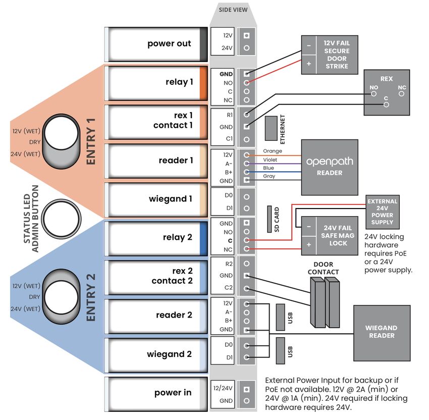
TABLE OF CONTENTS
REVISIONS                                                      2
TABLE OF CONTENTS                                              3
BEFORE YOU START                                               4
  CONDUCTING SITE SURVEYS                                      4
  FOR MORE INFORMATION                                         4
INSTALLATION                                                   5
  NETWORK REQUIREMENTS                                         5
  POWER REQUIREMENTS                                           5
  SELECTING A BACKUP BATTERY                                   6
  MOUNTING INSTRUCTIONS                                        6
     INSTALL ON A STANDARD US 1-GANGE BOX                      6
  MONITOR TAMPER ALERTS                                        7
  WIRING OPENPATH READERS                                      8
     WIRING INFORMATION                                        8
     STANDARD WIRING CONFIGURATION                            10
     WIRING FAIL SAFE AND FAIL SECURE LOCKING HARDWARE        10
PROVISIONING THE SDC                                           11
  REQUIREMENTS                                                12
  CREATE SDC                                                  12
     ADD MULTIPLE SDCS USING QUICK START OPTION               12
     ADD ONE SDC                                              13
  PROVISIONING STEPS                                         14
     PROVISION THE SDC USING THE OPEN ADMIN APP              14
  TROUBLESHOOTING THE SDC                                    16
  TEST INTERNET CONNECTION                                    17
  NETWORK SETTINGS                                            17
     CHANGE NETWORK SETTINGS                                 18
     SET UP WI-FI ON THE SDC                                 18
  COUNTRY SETTINGS                                           18
TROUBLESHOOTING                                              19
  SDC LEDS                                                   19
  RESETTING THE SDC                                          20
     SOFT RESET                                              20
     HARD RESET                                              20
  LEGACY WIRING                                               21
REGULATORY                                                    21
  UL 294                                                      21
  FCC                                                         21
  RF RADIATION HAZARD WARNING                                22
  INDUSTRY CANADA NOTICE AND MARKING                         22
WARNINGS                                                     23
SPECIFICATIONS                                               23

Rev. 1.7                                   © Openpath 2023    3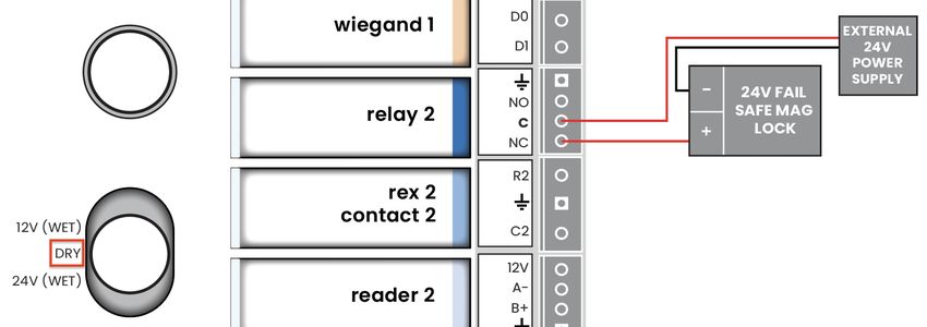
BEFORE YOU START
This Installation Guide explains how to install and configure the Openpath Embedded
USB Smart Reader (SDC) as part of an Openpath Access Control system.

CONDUCTING SITE SURVEYS
Before installing Openpath hardware, conduct a customer site survey to determine
the following:

    l   How many entries need to be configured (e.g. doors, gates, and elevator floors)
    l   Whether you're using legacy wiring or new wiring
    l   What kind of electronic entry mechanisms, Request to Exit (REX) mechanisms,
        and door contact sensors will be used and their power requirements.
    l   Whether you're providing backup batteries for the SDCs. See SELECTING A
        BACKUP BATTERY on page 6.
    l   Whether you're supporting a legacy access control panel for mobile gateway.

FOR MORE INFORMATION
    l   Openpath Smart Reader Datasheet
    l   Openpath Embedded USB Smart Reader Datasheet
    l   OPENPATH ACCESS CONTROL USER GUIDE FOR ADMINISTRATOR WEB PORTAL
    l   OPENPATH ACCESS CONTROL SYSTEM INSTALLATION GUIDE
    l   Openpath Embedded USB Smart Reader Installation Instructions (included in
        the box)

For additional product and support documentation, see support.openpath.com.

Rev. 1.7                              © Openpath 2023                                 4
INSTALLATION
NETWORK REQUIREMENTS
An Ethernet connection with DHCP can be used to connect the SDC to the Local Area
Network (LAN). You also need to configure firewall settings to communicate with the
Openpath system, which uses the following outbound ports:

    l   TCP port 443
    l   UDP port 123

 Note: If using an external DNS server, the outbound UDP port 53 must also be open.

To support Wi-Fi unlocking from the mobile app, the inbound TCP port 443 of the SDC
must be available from within the LAN. Inbound port forwarding on the router, firewall,
or NAT device is not required.

The SDC also supports Wi-Fi connections. Refer to NETWORK SETTINGS on page 17.

POWER REQUIREMENTS
The Openpath SDC can be powered with PoE, PoE+, and/or an external 12-24V supply.
The SDC will automatically switch to the higher voltage source if both PoE and an
external source are available. Openpath recommends using a backup battery in
case of power failures on the external 12-24V supply or the PoE supply.

Operating Voltage: 12-24VDC

Input Rating: 12V @ 2A (min) or 24V @ 1A (min)

Output Ratings:

    l   Power Out connector can supply up to 100mA @ 12V or 50mA @ 24V
    l   2 reader ports, max power output: 250mA @ 12V each
    l   2 relays, max power output:
            o PoE: Max 3W combined output (e.g. 250mA @ 12V or 125mA @ 24V)

            o PoE+: Max 9W combined output (e.g. 750mA @ 12V or 375mA @ 24V)

Rev. 1.7                             © Openpath 2023                                  5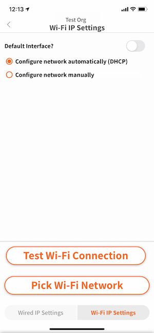
SELECTING A BACKUP BATTERY
While not required, Openpath recommends having a backup battery in case of power
outages. The size of battery depends on your setup and how long you want to power
the system.
Table 1 Power requirements (24V)
SDC .3A
Smart Reader (2) 0.25A
Locking hardware (while engaged) 0.25A--0.5A
Assuming an external 24V power supply, an SDC configured with two Openpath
Readers and locking hardware uses about 1.1 Amps. To keep the system running for 3
hours with all entries engaged, you need 1.1A x 3 hours = 3.3 AH, so two 12V 4AH sealed
lead acid (SLA) or gel cell batteries in series.
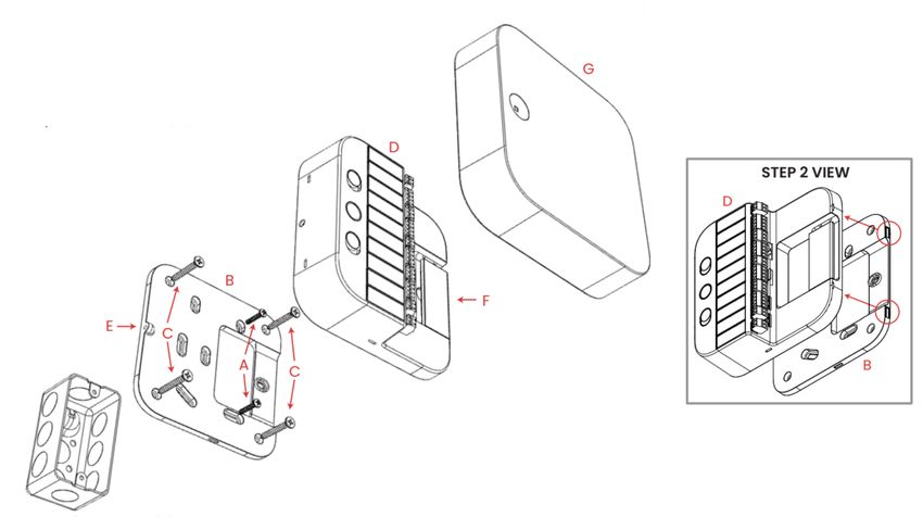
MOUNTING INSTRUCTIONS
The SDC can be mounted a few different ways: on a single or double gang box or on
drywall.
INSTALL ON A STANDARD US 1-GANGE BOX
1. Use two 6-32 screws (A) to attach backplate (B) to gang box.
Recommended: Use the provided drywall screws (C) and anchors (not shown)
on drywall for added stability.
2. Snap on main housing (D) to backplate (B).
3. On the right side of the main housing (D), ensure that the two edge clips fit into
their respective notches on the backplate (B).
4. Press firmly on the main housing (D) to snap into place.
5. Partially unscrew the pre-installed M4 set screw (E) to secure main housing (D)
to backplate (B).
6. Use the cable slot (F) to hold cables while wiring; see STANDARD WIRING
CONFIGURATION on page 10.
7. Snap on front cover (G).
Rev. 1.7 © Openpath 2023 6Note: For a double gang box, follow the directions above, using additional 6-32
screws.
Figure 1 Mounting SDC to wall
1. Use the provided drywall screws (C) and anchors (not shown) to attach
backplate (B) to wall.
2. Snap on main housing (D) to backplate (B).
3. On the right side of the main housing (D), ensure that the two edge clips fit into
their respective notches on the backplate (B).
4. Press firmly on the main housing (D) to snap into place.
5. Partially unscrew the pre-installed M4 set screw (E) to secure main housing (D)
to backplate (B).
6. Use the cable slot (F) to hold cables while wiring; see STANDARD WIRING
CONFIGURATION on page 10 .
7. Snap on front cover (G).
MONITOR TAMPER ALERTS
The front cover of the SDC has a built-in tamper sensor and will report tamper events
when the cover is removed. You can monitor tamper events using the Tamper
Detector State Changed alert. Refer to How do I set up alerts?
Rev. 1.7 © Openpath 2023 7WIRING OPENPATH READERS
Openpath Readers and SDCs communicate via RS-485. The following wire types are
compatible, listed in the order of preference which impacts distance.
l Shielded CAT6A (recommended, additional two pairs can be used for sensors)
l Shielded CAT6
l Shielded RS485 w/22-24AWG (lower gauge, thicker wire is better)
l Shielded CAT5
l Unshielded CAT6
l Unshielded CAT5
l Shielded 22/6
l Unshielded 22/6
Ideally, use one twisted pair for GND and VIN (power) and one twisted pair for +B and
-A (data).
Note: The Openpath Embedded USB Smart Reader can be wired via RS-485, or
connected using the micro USB port and the cable provided in the box. Only one
method, RS-485 or micro USB port, can be used at the same time. For more
information, see the Openpath Embedded USB Smart Reader Datasheet and the
Openpath Embedded USB Smart Reader Installation Instructions (included in the
box). The Openpath Embedded USB Smart Reader supports only Openpath Mifare
or DESFire EV3 card credentials. Mobile credentials are not supported at this time.
WIRING INFORMATION
Rev. 1.7 © Openpath 2023 8Recommended maximum cable length: 300 ft (91 m) with CAT6 or 500 ft (152 m) if two wire pairs are used for GND and VIN (power). For shielded wiring: Connect one side of the drain wire (the shield around the wires) to the GND terminal on the SDC. Both the shield and the GND wire can share the same GND terminal. Do not connect the other side of the shield to anything. For standard reader installation: We recommend that you install a 1-Gang 20 CU box in order to flush-mount the reader. Alternatively, the reader may also be surface mounted with the included back plate. Note: For elevators, all relays and readers must be connected to the same SDC. If you need more than four access controlled floors or readers, add the Openpath Elevator Expansion Module. WARNING: Always remove power from the SDC and locking hardware when wiring readers and other devices. Failure to do so can damage the SDC. Rev. 1.7 © Openpath 2023 9
STANDARD WIRING CONFIGURATION

                                Figure 2 Example SDC wiring

WIRING FAIL SAFE AND FAIL SECURE LOCKING HARDWARE

Fail safe and fail secure are ways of configuring locking hardware:

    l   Fail safe hardware unlocks when power is interrupted.
    l   Fail secure hardware locks when power is interrupted.

VOLTAGE SWITCHES

 WARNING: Remove the DC Input Power and PoE before changing the voltage of
 the relays.

Rev. 1.7                              © Openpath 2023                        10
To power locking hardware without an external supply (Wet Relay), select 12V or 24V,
and connect locking hardware to NO and GND (for fail secure locks) or NC and GND
(for fail safe locks).
Figure 3 Wet Relay example
To use external power, select DRY and use NO or NC and C, and wire to external
supply.
Figure 4 Dry Relay example
PROVISIONING THE SDC
Provisioning the SDC means registering it in the Control Center and getting it up and
running with the latest firmware. You will need to re-provision in the case of RESETTING
THE SDC on page 20.
Note: If you're provisioning SDCs for a customer account, the customer org needs
to be created first.
Rev. 1.7 © Openpath 2023 11REQUIREMENTS
l Meet all NETWORK REQUIREMENTS on page 5.
l Connect the ACU to the Internet via Ethernet.
l Install the Open Admin app.
o iOS App Store
o Google Play™ Store
l If using a laptop instead of the app, the laptop must be on the same network as
the SDC. If you have a VLAN, make sure the laptop is on the same VLAN as the
SDC.
l If using a laptop running Microsoft™ Windows or Linux®, you must download the
iTunes app. The provisioning process uses Bonjour software that comes with
iTunes. Optionally, you can download iTunes and use an archive utility to extract
and install only the Bonjour MSI.
CREATE SDC
Before you can provision an SDC using the Open Admin app, you must first create an
SDC in the Control Center.
ADD MULTIPLE SDCS USING QUICK START OPTION
1. Go to control.openpath.com/login and log in. To access the European Partner
Center, go to control.eu.openpath.com/login.
2. Go to Administration > Quick start.
3. Enter a Site Name and any other relevant site information.
a. In Organization Language, select the preferred language for the emails
sent by the system.
b. Click Next.
4. Enter the number of controllers located at your site:
a. Enter names for the controllers.
b. In Controller Type, select Single Door Controller (SDC).
c. If your SDC also connects to an expansion board, add the appropriate
types in EXPANSION BOARDS:
l Openpath 4-Port Expansion
l Openpath 8-Port Expansion
Linux® is the registered trademark of Linus Torvalds in the U.S. and other countries.
Rev. 1.7 © Openpath 2023 12l Openpath 16-Port Elevator
Tip: This configuration is most common with the Core Series Smart
Hubs.
d. Click Next.
5. Enter the number of readers connected to the controllers. Enter their names and
click Next.
6. Review your site details and click Confirm & Submit. It may take a few minutes
for setup to complete.
ADD ONE SDC
1. Go to Devices > ACUs.
2. To add a new SDC, click the Add ACU button in the upper-right corner.
3. Enter a name for the SDC.
4. In Controller Type, select Single Door Controller (SDC).
5. If your SDC also connects to an expansion board, add the appropriate types in
EXPANSION BOARDS:
l Openpath 4-Port Expansion
l Openpath 8-Port Expansion
l Openpath 16-Port Elevator
Tip: This configuration is most common with the Core Series Smart Hubs.
6. Click Save.
Rev. 1.7 © Openpath 2023 13Figure 5 Create ACU
PROVISIONING STEPS
PROVISION THE SDC USING THE OPEN ADMIN APP
1. If powering using PoE, plug in Ethernet; if powering with an
external power supply, plug in Ethernet and connect power to
POWER IN.
The Status LED will be solid cyan.
2. In the Open Admin app, locate the org to which you're
provisioning hardware, either on the list or using search, then
tap on the org name.
3. Wait until the Status LED is solid blue, then press the Admin
button (Figure 6 on page 16) on the SDC.
Note: SDC will disconnect from the Open Admin app after 5
minutes of inactivity; press the Admin button again to reset the
timer.
4. When the Status LED is blinking purple, In the app, tap on the
last four digits of the serial number for the SDC.
Rev. 1.7 © Openpath 2023 145. When the Status LED changes to solid purple, tap Test Internet
Connection and wait for a green YES to appear before
proceeding to the next step.
Note: This checks if the ACU/SDC can ping
https://api.openpath.com/.
If this step fails, refer to PROVISIONING STEPS on the previous
page.
6. If the Internet connection test is successful, tap Provision Device
in the app.
7. Tap on the ACU Name that you want to provision to (this is the
name of the SDC you created in the Control Center), then tap
Yes to proceed.
8. The Status LED will blink yellow; the app will send notifications
when the SDC provision state changes from Unprovisioned to
Provisioning in progress to Provisioning complete.
9. When setup is complete, the Status LED will change to solid
white.
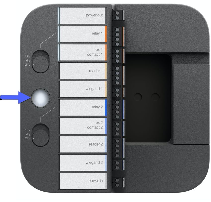
Rev. 1.7 © Openpath 2023 15Figure 6 SDC Admin button
TROUBLESHOOTING THE SDC
If at any point the Status LED blinks red, this indicates there is an issue
connecting to the Internet. If attempting to set up using Wi-Fi, try
switching to an Ethernet connection.
Refer to NETWORK REQUIREMENTS on page 5.
If at any point the Status LED is solid red, this indicates the SDC is in an
error state. Go to the Devices dashboard in theControl Center and
restart the services listed under Remote Diagnostics. If this doesn't
work, power cycle the SDC (remove power, wait 10 seconds, apply
power). If the error persists, contact Openpath support.
Rev. 1.7 © Openpath 2023 16Figure 7 SDC Admin button TEST INTERNET CONNECTION In the Open Admin app, you can tap Test Internet Connection to check if the SDC can ping https://api.openpath.com/health. NETWORK SETTINGS In the Open Admin app, you can configure network settings for the SDC. While wired Internet connections are preferred, you can configure the SDC to use Wi-Fi instead. The default interface for the SDC is Ethernet/wired connection. Ethernet and Wi-Fi connections can be DHCP (default) or can have a static IP address. The SDC supports 2.4 GHz and 5 GHz Wi-Fi connections. Rev. 1.7 © Openpath 2023 17
CHANGE NETWORK SETTINGS

  1.   Connect to the Core by pressing the Admin button again, if needed.
  2.   Connect to the SDC by pressing the Admin button again, if needed.
  3.   Tap on Network Settings.
  4.   Select Configure network manually.
  5.   Configure the network settings as needed. Set a static IP address or set a
     preferred DNS server.
  6. Tap Save on the top-right corner.

SET UP WI-FI ON THE SDC

  1.   Connect to the SDC by pressing the Admin button again, if needed.
  2.   Tap on Network Settings.
  3.   Tap on Wi-Fi IP Settings.
  4.   Enable Default Interface.
  5.   Tap on Pick Wi-Fi Network.
  6.   Choose your network and enter your password, then tap Connect.

                              Figure 8 Admin App Wi-Fi Settings

COUNTRY SETTINGS
The country code on the SDC is automatically set up during initial connection and
provisioning based on information from the Open Admin app of the installer. This

Rev. 1.7                               © Openpath 2023                              18
setting cannot be changed by the installer. If you need to change the country code,
please contact Openpath Support.
TROUBLESHOOTING
SDC LEDS
The Status LED on the Openpath SDC indicates the following:
Solid White indicates the SDC is provisioned and functioning
normally.
Blinking Red indicates there is a problem with the Internet
connection.
Solid Cyan appears when the SDC is booting.
Solid Yellow indicates that the SDC is restoring software; appears
when you turn on the SDC for the first time.
Blinking Yellow indicates that the SDC is updating software; appears
when the SDC has been online for less than 24 hours.
Solid Blue indicates that the SDC has finished booting and is ready for
provisioning.
Solid Purple indicates that the SDC is connected to the Open Admin
app.
Blinking Purple indicates the SDC is ready to connect to the Open
Admin app.
Solid Red indicates the SDC is in an error state. Refer to
TROUBLESHOOTING THE SDC on page 16.
The Openpath SDC has eight port LEDs and two power LEDs. The port LEDs indicate the
following:
Rev. 1.7 © Openpath 2023 19l Openpath Readers or Wiegand Readers
o Solid: Normal operation
o Blinking: Error state
l Sensors (including REX and Contact Sensors)
o Solid: Active
o Blinking: EOL shorted or cut
l Locking hardware (relays)
o Solid: Relay is energized
o Blinking: Fault detection
Figure 9 SDC Port LED descriptions
RESETTING THE SDC
SOFT RESET
To soft reset the SDC, disconnect power from the SDC, wait 10 seconds, then
reconnect the power.
HARD RESET
WARNING: Only hard reset the SDC if absolutely necessary and if instructed by
Openpath. This will clear all of the data off of the ACU and will require
reprovisioning.
1. Disconnect power from the SDC.
2. Press the ADMIN button for 15 seconds (see Figure 6 on page 16).
3. While still pressing the ADMIN button, reconnect the power, and continue to hold
the button for another 15 seconds until the Status LED turns yellow, then release.
Rev. 1.7 © Openpath 2023 204. Wait 15 minutes or until the Status LED turns blue before PROVISIONING THE SDC
on page 11.
LEGACY WIRING
Sometimes legacy wiring (unshielded and straight through, rather than shielded
twisted pair, often 22-6) results in slower connections and dropped packets between
the Openpath Reader and SDC. To remedy this, you can switch GND and VIN with +B
and -A connections on the SDC and readers to ensure the data pair (+B and -A) are
using the alternate pair of legacy wires.
REGULATORY
All national and local electrical codes apply.
UL 294
The following performance levels are defined for the Openpath Single Door Controller,
as per UL 294:
Attack: Level I
Endurance: Level I
Line Security: Level I
Standby: Level I
FCC
This device complies with part 15 of the FCC Rules. Operation is subject to the
following two conditions: (1) This device may not cause harmful interference, and (2)
this device must accept any interference received, including interference that may
cause undesired operation. To comply with FCC RF exposure compliance
requirements, a separation distance of at least 20 cm should be maintained between
the antenna of Openpath Smart Reader(s) and persons during operation.
NOTE: This equipment has been tested and found to comply with the limits for a Class
A digital device, pursuant to part 15 of the FCC Rules. These limits are designed to
provide reasonable protection against harmful interference when the equipment is
operated in a commercial environment. This equipment generates, uses, and can
radiate radio frequency energy and, if not installed and used in accordance with the
instruction manual, may cause harmful interference to radio communications.
Rev. 1.7 © Openpath 2023 21Operation of this equipment in a residential area is likely to cause harmful interference in which case the User will be required to correct the interference at his own expense. This equipment complies with FCC RF radiation exposure limits set forth for an uncontrolled environment. This equipment should be installed and operated with a minimum distance of 20 centimeters between the radiator and your body. OP-2ESH-POE: FCC ID: 2APJV-2ESH RF RADIATION HAZARD WARNING To ensure compliance with FCC and Industry Canada RF exposure requirements, this device must be installed in a location where the antennas of the device will have a minimum distance of at least 20 cm from all persons. Using higher gain antennas and types of antennas not certified for use with this product is not allowed. The device shall not be co-located with another transmitter. Installez l'appareil en veillant à conserver une distance d'au moins 20 cm entre les éléments rayonnants et les personnes. Cet avertissement de sécurité est conforme aux limites d'exposition définies par la norme CNR-102 at relative aux fréquences radio. INDUSTRY CANADA NOTICE AND MARKING Under Industry Canada regulations, this radio transmitter may only operate using an antenna of a type and maximum (or lesser) gain approved for the transmitter by Industry Canada. To reduce potential radio interference to other Users, the antenna type and its gain should be so chosen that the equivalent isotropically radiated power (e.i.r.p.) is not more than that necessary for successful communication. Conformément à la réglementation d'Industrie Canada, le présent émetteur radio peut fonctionner avec une antenne d'un type et d'un gain maximal (ou inférieur) approuvé pour l'émetteur par Industrie Canada. Dans le but de réduire les risques de brouillage radioélectrique à l'intention des autres utilisateurs, il faut choisir le type d'antenne et son gain de sorte que la puissance isotrope rayonnée équivalente (p.i.r.e.) ne dépasse pas l'intensité nécessaire à l'établissement d'une communication satisfaisante. This device complies with Industry Canada licence-exempt RSS standard(s). Operation is subject to the following two conditions: (1) this device may not cause Rev. 1.7 © Openpath 2023 22
interference, and (2) this device must accept any interference, including interference
that may cause undesired operation of the device.

Le présent appareil est conforme aux CNR d'Industrie Canada applicables aux
appareils radio exempts de licence. L'exploitation est autorisée aux deux conditions
suivantes : (1) l'appareil ne doit pas produire de brouillage, et (2) l'utilisateur de
l'appareil doit accepter tout brouillage radioélectrique subi, même si le brouillage est
susceptible d'en compromettre le fonctionnement.

WARNINGS
      l    Disconnect power before servicing.
      l    Do not plug into an outlet controlled by an on/off switch.

SPECIFICATIONS

 Note: For the Openpath hardware specifications, refer to the product datasheets
 on page 4.

                       Table 2 Electrical specifications of Openpath hardware

 Single Door Controller (OP-2ESH-POE)              12-24VDC, 0.3A @ 24V

 Video Reader Pro                                  Input Voltage: PoE (48V)

                                                   Power Consumption: 7.8W

 Smart Reader v2 (OP-R2-STND,                      12-24VDC, 0.25A @ 12V, 0.12A @ 24V

 OP-R2-MULL)                                       OP-R2-STND: FCC ID: 2APJVOPR2LHF

                                                   OP-R2-MULL: FCC ID: 2APJVOPR2LHF

 Smart Readers (OP-RLF-STD, OP-RHF-                12VDC, 0.25A
 STD, OP-RLF-MULB, OP-RHF-MULB, OP-
                                                   OP-RLF-STD/MULB: FCC ID: 2APJVOPRLF
 R2LHF-STD, OP-R2LHF-MUL)
                                                   OP-RHF-STD/MULB: FCC ID: 2APJVOPRHF

                                                   OP-R2LHF-STD: FCC ID: 2APJVOPR2LHF

Rev. 1.7                                  © Openpath 2023                                23
OP-R2LHF-MUL: FCC ID: 2APJVOPR2LHF 4 Door Controller (OP-AS-01/OP- 10-14VDC, 1A 4ECTR) 16 I/O Elevator Board (OP-16EM) 12-24VDC, 0.35A @ 12V, 0.2 @ 24V 4-Port Board (OP-EX-4E) 12-24VDC, 0.4A @ 24V 8-Port Board (OP-EX-8E) 12-24VDC, 0.6A @ 24V Access Control Core (OP-ACC) 12-24VDC, 0.4A @ 12V, 0.2A @ 24V Smart Hub with 12/24V Supply (OP- 120V, 0.7A or 230V, 0.3A, 50/60 Hz 4ESH-24V) Rev. 1.7 © Openpath 2023 24
You can also read