Optimizing a Championship - NASCAR mentor.com/mechanical Fujifilm Camera Design
←
→
Page content transcription
If your browser does not render page correctly, please read the page content below
Vol. 05 / Issue. 02 / 2016

EDGE
                                          Accelerate Innovation
                                          with CFD & Thermal
                                          Characterization

Optimizing a        Fujifilm   Robert
Championship        Camera     Bosch India
NASCAR              Design     Drives ECU
Racing              Page 24    Temperatures
Machine                        Down
Page 14                        Page 37
mentor.com/mechanical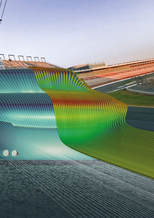
2 mentor.com/mechanical
Perspective
                                                                 Vol. 05 / Issue. 02 / 2016

               EDGE
                                                           Accelerate Innovation
                                                           with CFD & Thermal
                                                           Characterization

                                                                                              Vol. 05, Issue. 02

                                                                                                                  Greetings readers! It is nearly five years since the
                                                                                                                  Flowmaster® product-line joined Mentor Graphics and this
                Optimizing a        Fujifilm    Robert
                Championship
                NASCAR
                                    Camera
                                    Design
                                                Bosch India
                                                Drives ECU                                                        edition celebrates its first major release, V8.0 which has
                Racing              Page 24     Temperatures
                Machine
                Page 14
                                                Down
                                                Page 37                                                           also been rebranded to: FloMASTER™. This is a major
                                                                                                                  overhaul of the product (see Product News page 8) with a
                mentor.com/mechanical

                                                                                                                  new user experience Launchpad interface, a new Simulation
                                                                                                                  Based Characterization (SBC) capability that is unique
                                                                                                                  to a 1D thermo-fluid system simulation tool, and physics
                                                                                                                  improvements in a number of areas, not least of which a new
                Mentor Graphics Corporation                                                   Waste Heat Recovery capability. SBC is effectively a 3D CFD capability (based
                       Pury Hill Business Park,                                               on FloEFD™ technology) embedded within a 1D CFD code. This unites two of
                                  The Maltings,                                               our strengths – system level thermo-fluid modeling and fast CAD-embedded 3D
                        Towcester, NN12 7TB,                                                  CFD component simulation and characterization. This will transform the way
                               United Kingdom                                                 that 1D systems engineers engage with 3D CFD, make systems simulations
                      Tel: +44 (0)1327 306000                                                 more accurate, and speed up the 3D to 1D CFD workflow dramatically. Nothing
                        email: ee@mentor.com                                                  else like it exists on the CFD market.

                                                               Editor:                        I am also pleased to report that our Don Miller Award for Excellence in Thermo-Fluid
                                                          Keith Hanna                         System Simulation in its second year has been awarded to Chrysler India Automotive
                                               Managing Editor:                               for their great experimental validation of Flowmaster in various automotive thermal
                                                Natasha Antunes                               management applications. Our new 2016 Frontloading CFD Award for the best
                                                                                              applications of FloEFD early in a design process has been awarded to Automotive
                                                      Copy Editor:                            Lighting in America who had a body of work on how they improved their headlight
                                                       Jane Wade                              design process. This year we hosted a FloEFD User Conference in Frankfurt,
                                   Contributors:                                              Germany, in early November which was a great forum for FloEFD users to hear of
 Sergio Antioquia, Robin Bornoff, Mike Croegaert,                                             the advances going on with this next-wave CFD product and to network with other
  Mike Gruetzmacher, Keith Hanna, Doug Kolak,                                                 FloEFD users.
     Boris Marovic, John Murray, Sawako Ofuchi,
    John Parry, Nazita Saye, Tatiana Trebunskikh,                                             The breadth of customer stories in this edition of Engineering Edge is truly broad
                                     Gang Wang                                                with automotive and ground transportation taking prominence. Delphi, Robert Bosch
                                                                                              India, Continental, Voxdale, CSEG and EC-Power all feature in this industry sector
                          With special thanks to:                                             with applications ranging from HEV battery modeling to NASCAR and a Wind Tunnel
                                 Anthony Kumpen,                                              design. Fujifilm describe how they develop camera electronics using FloTHERM.
                                  Axis Engineering,                                           Mitsubishi Materials have developed a clever multi-software simulation approach to
                                             CSEG,                                            designing liquid cooling of machining tools. ShinEtsu, IMS in Bordeaux and our own
                                             Esteq,                                           AE, Gang Wang, in China describe T3Ster ® applications ranging from TIM materials
                                            Fujifilm,                                         to Lasers and automotive headlights showing the versatility of our MicReD® thermal
    Hyundai Heavy Industries Analysis of Pressure                                             testing technology. Two great Flowmaster stories are included: Hyundai Heavy
       Surge in Offshore Floating Production Unit,
                                                                                              Industries in Korea and Robin Bornoff’s N-Arm How to Guide as well as the use of
          Institute of Microelectronics, Singapore,
                                                                                              FloEFD to simulate turbochargers at Tamturbo in Finland.
                                   Laboratoire IMS,
                               Mitsubishi Materials,
                                                                                              Finally, we recently joined the power electronics Wide Band Gap initiative (WBGi)
                               Robert Bosch India,
                                                                                              consortium in Japan led by Professors Suganuma and Funaki of Osaka University.
                    Shin-Etsu Chemicals Co., Ltd.,
                                                                                              This cements our ongoing commitment to this sector globally with our MicReD
                                      Tamturbo Oy,
                                                                                              hardware and electronics cooling software product-lines.
                    TsAGI & Irkut Corporation, and
                                      Voxdale bvba

             ©2016 Mentor Graphics Corporation,
      all rights reserved. This document contains
           information that is proprietary to Mentor
   Graphics Corporation and may be duplicated
        in whole or in part by the original recipient
    for internal business purposes only, provided
   that this entire notice appears in all copies. In
 accepting this document, the recipient agrees
       to make every reasonable effort to prevent
               unauthorized use of this information.
All trademarks mentioned in this publication are                                              Roland Feldhinkel, General Manager,
       the trademarks of their respective owners.                                             Mechanical Analysis Division, Mentor Graphics

                                                                                                                                                     mentor.com/mechanical         3
14

News                       Engineering Edge                          46 Institute of
                                                                        Microelectronics
6  New Release             14 Voxdale bvba                              Liquid Cooling Technology

   FloEFD™ V16                Optimizing a NASCAR Racing Machine     50 CSEG
7 Introducing FloEFD™      20 Tamturbo Oy                               Predicting Automotive
                              Air Dynamics Simulation of                Cold-Ambient Warm-Up Performance
   for Solid Edge®            an Oil-Free Air Turbo Compressor       54 Shin-Etsu
8 New Release              24 Fujifilm                                  Chemicals Co., Ltd.
   FloMASTER™ V8              FloTHERM Camera Design                    Thermal Effects of Surface Roughness

9 Frontloading CFD         28 Mitsubishi Materials                      on TIMS

   Award Announcement         Design of Liquid-Cooled Nozzles        58 Voxdale bvba
                              for Cutting Tools                         Building a Wind Tunnel with FloEFD
10 Don Miller Award        37 Robert Bosch India                     60 TsAGI & Irkut
   Announcement               Driving ECU Temperatures Down
                                                                        Corporation
13 Automotive Lighting     42 Hyundai Heavy                             Cleared for Landing
   Master’s Degree            Industries                             66 Laboratoire IMS
   Program                    Analysis of Pressure Surge                Laser Diode Design Optimization
                              in Offshore Floating Production Unit
13 Mentor Graphics joins
   WBG-i Consortium

4 mentor.com/mechanical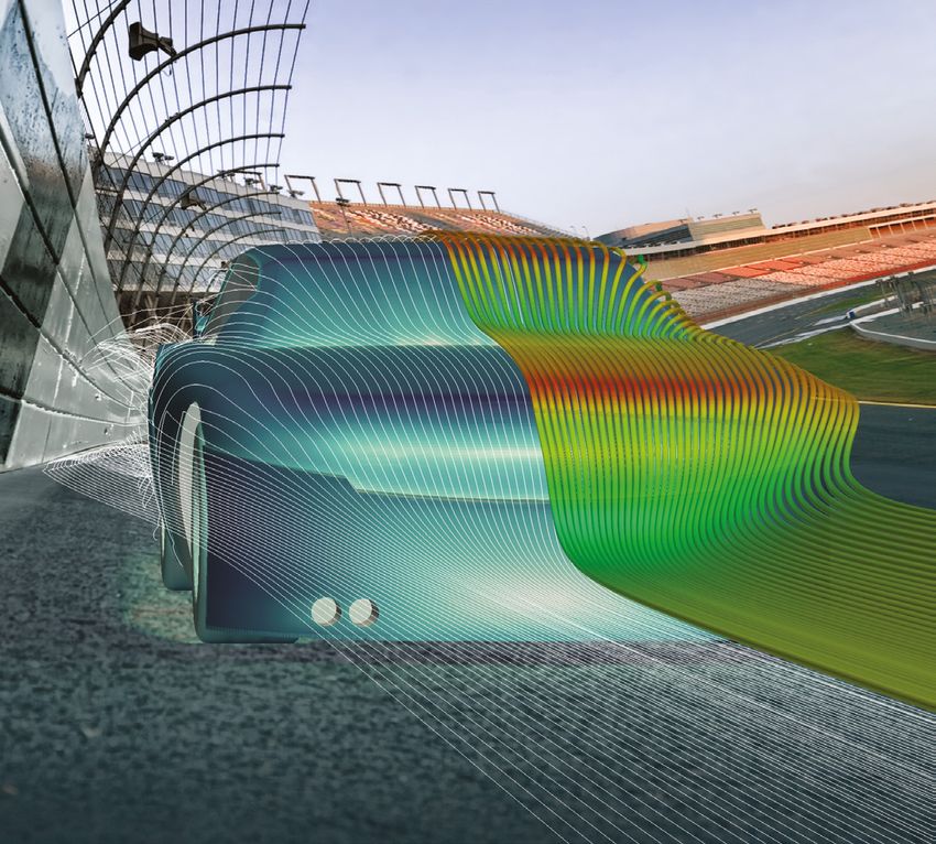
Contents

                         42
Technology &
Knowledge Bank
32 Thermal Testing of
   an Automotive LED
   Fog Light
52 Predicting Electric
   Vehicle Drive Range
   with AutoLionST™
   & Flowmaster

                              Regular Features
 32                           18 How to...
                                 Create FloMASTER N-Arm Components

                              26 Interview
                                 Dr. Uwe Lautenschlager, Continental

                              40 Ask the CSD Expert
                                 Gas Turbine Secondary Airflow

                              70 Geek Hub
                                 Ever wondered if a LEGO Aero
                                 Hawk Helicopter could actually fly?

                              74 Brownian Motion

26                       70

                                       mentor.com/mechanical           5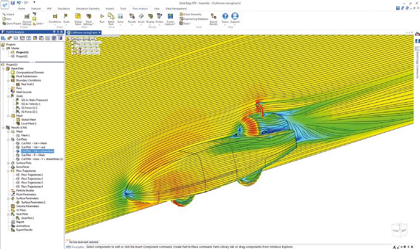
New Release:
FloEFD 16
T
         he newest release of the leading
         frontloading Computational
         Fluid Dynamics (CFD) product,
         FloEFD™ targets complex design
challenges. Frontloading CFD refers to the
practice of moving CFD simulation early
into the design process, enabling design
engineers to examine and evaluate design
options, resulting in optimized product
performance and reliability. The new
FloEFD release provides the industry’s            Figure 1. Radiation Spectrum and Pattern Essential for   Figure 2. LED Radiation Pattern
                                                  Laser Diode Simulation
first simulation solution for water vapor
absorption alongside several other
lighting related functionalities.

• Water Sorption by Plastics: With the
  latest version of FloEFD, users can now
  simulate the sorption (when one substance
  permeates another) and desorption
  (changing from an adsorbed state to a
  gaseous or liquid state) processes. For
                                                  Figure 3. DoE and Response Surface Optimization          Figure 4. Project Conditions from a Component for
  example, plastic absorbs water and then                                                                  Simulation of the Entire Assembly
  releases it when environmental conditions
  change. This functionality is important for
  several key markets such as automotive             by saving model components with FloEFD
  lighting design where moisture needs               conditions for future use, to be shared
  to be minimized in light housings. Other           with other designers in the organization.
  automotive lighting related capabilities
  include radiation and spectrum for direction    • Radiation and LED Enhancements: The
  source modeling, and LED thermal-optical          radiation modeling capability for FloEFD
  modeling to simulate LEDs with non-linear         has been further extended to include
  dependence of parameters on temperature.          radiation pattern and spectrum definitions
                                                    for directional sources. The LED thermal-
                                                    optical model is now capable of simulating             Figure 5. Acoustic Power Level – a new Feature in
While we continue to make the software
                                                                                                           FloEFD 16 to Estimate Broadband Noise
faster and more efficient, the focus of FloEFD      LEDs with non-linear dependency of
16 is on power and the ability to handle even       parameters on temperature. These                       • Korean Localization: FloEFD is now the
more complex tasks:                                 improvements are ideal for automotive                    only CFD software with user interfaces
                                                    lighting design and simulation.                          in Japanese, Chinese, French, German,
• Linked Data from Components:                                                                               Russian, English and now Korean,
                                                  • Transient Explorer: The new method
  Often the design of complex devices                                                                        allowing engineers to experience FloEFD
                                                    of results data compression saves large
  assumes a multi-level simulation approach                                                                  in their preferred language.
                                                    amounts of disc space while it provides
  when analysis is initiated from a simple
                                                    access to transient data immediately.
  component, followed by an assembly                                                                       “Our customers require fast and accurate
                                                    Users can combine the transient
  of components, then finally the full                                                                     simulation results for their complex
                                                    animation of plots and parameter charts
  system comprise many components and                                                                      engineering problems,” said Roland
                                                    into a single view.
  sub-assemblies. Using the new FloEFD                                                                     Feldhinkel, General Manager of Mentor
  product, users can move from level to           • Design of Experiment (DOE) and                         Graphics Mechanical Analysis Division.
  level, and re-use the component task              Optimization: True optimization of designs             “Our latest FloEFD product provides the
  definition of an assembly, saving a great         requires that multiple criteria be considered          power, special functionality and performance
  amount of time by eliminating the need            concurrently; as such its implementation               required by engineers to obtain meaningful
  to repeat component or sub-assembly               can consume substantial resources (such                answers to their questions without disrupting
  definition. Users simply link to a previously     as time and computing power). With the                 their design process.”
  created project in just seconds, minimizing       addition of this functionality now users can
  the risk of manual entry errors. In addition,     take advantage of DoE and Response                     For additional product information, visit the
  users can create a library of components          Surface optimization.                                  website: www.mentor.com/floefd

6 mentor.com/mechanical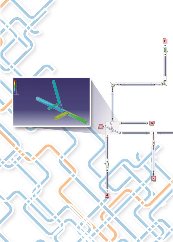
News

FloEFD for Solid Edge

M
             entor Graphics® is pleased      necessary translations and cavity modeling,       real-time feedback and timely outputs
             to announce the only fully-     and generates an optimized mesh before            that can be generated quickly in MS
             embedded Computational          executing analysis. This approach provides        Word and Excel.
             Fluid Dynamics (CFD)            accurate analysis results quickly thus
                                                                                            • Parametric study enables user to
solution for Solid Edge® users. Solid        enabling designers to validate their designs
Edge is a product lifecycle management       early and often. It also allows the designer     compare a wide range of project
(PLM) suite of software tools addressing     to explore a succession of ideas without         variations.
all aspects of the product development       risking project deadlines.                     • Fast, automated SmartCell™ meshing
process, from 3D design through                                                               technology to create realistic simulations
to manufacturing from Siemens                The new FloEFD product for Solid Edge            for complex 3D models including rotating
Corporation. For the first time, Solid       helps companies conduct analysis earlier         equipment and transient flow behaviors -
Edge customers can take advantage of         in the design process. Engineers can             providing unprecedented speed-up in the
Mentor Graphics FloEFD™ frontloading         operate within their preferred and familiar      overall design process.
CFD product and use simulation in their      MCAD interface thus reducing design cycle
design process. The FloEFD solution          times by an order of magnitude compared        “Mentor’s FloEFD frontloading CFD
for Solid Edge is especially well suited     to traditional methods and tools while         technology full-featured 3D analysis
for use during the design process as it      increasing design quality:                     eliminates workflow complexity and meshing
reduces overall time to a solution by as                                                    overheads compared to other available CFD
much a 65%-75% compared to other             • Robust 3D fluid flow and heat transfer       software,” said Roland Feldhinkel, General
CFD tools.                                     analysis software capable of solving         Manager of Mentor Graphics Mechanical
                                               complex real-life engineering problems.      Analysis Division. “We believe Solid Edge
Mentor Graphics’ award-winning FloEFD        • Fully-embedded in Solid Edge, FloEFD         customers will reap tremendous value in
CFD solution automates the most onerous        technology allows users to conduct           using our FloEFD solution for CAD-centric
CFD steps which include transferring model     multiple design studies and evaluate how     CFD design and performance optimization,
geometry to the CFD application, modeling      the modifications influence the design       while reducing time and costs to meet their
internal cavities if needed, and creating                                                   product delivery goals.”
                                               performance immediately.
a “mesh.” The FloEFD CFD technology
takes the geometry directly from the CAD     • Features an intuitive user interface with    For more information visit:
application, automatically performs the        built-in intelligent automation including    www.mentor.com/floefd

                                                                                                         mentor.com/mechanical         7
New Release:
FloMASTER™ V8.0
3D CFD Connectivity, Usability & New Physics Capabilities

F
        loMASTER V8 is an extremely
        significant release. Not only does
        it contain a number of powerful
        features aligned around the three
pillars of user experience, physics and
connectivity; it represents the first major
step toward a completely revitalised
product. John Murray, FloMASTER Product
Manager: “Flowmaster has been a huge
commercial success, precisely because it
solved a genuine market problem and was
staffed by engineers enthusiastic about
doing just that. We haven’t changed that,
but what is significant about FloMASTER
is that we’re recognising that the world
hasn’t stayed still since V7 was released;
expectations and needs have evolved
and we recognise that and have adapted
ourselves accordingly. This is a huge
release and is the result of over 42 man
years of R&D. Accuracy has always been
at the heart of the FloMASTER ethos
and during the development we have run
~133,000 regression network cycles and
~13,000,000 unit test runs.”                     be considered ‘standard’ geometries, e.g.       software. V8.0 is the first tranche of these
                                                 bends, diffusers etc. For the increasingly      User Experience (UX) improvements
The three key areas of development are           common bespoke geometries made possible         delivering a number of important features.
Connectivity, User Experience and Physics        by modern manufacturing techniques,             One of the most prominent deliverables from
with the new Waste Heat Recovery                 integration with FloEFD in order to             this effort at V8 will be the new Launchpad
functionality.                                   characterize hydraulic and thermal behavior     functionality:

3D CFD Connectivity                              • Significantly reduces time and cost to get    Launchpad is a hub for FloMASTER, helping
At the market level, it’s been about working       essential component information;              users launch key features, access previous
with colleagues within the Mechanical            • Does not require specialized resources or     work and also discover the solutions the
Analysis Division to identify important trends     facilities; and                               product has to offer. Recent networks are
and areas in which the Mechanical product                                                        promoted and Sample Systems, complete
portfolio can come together in order to          • Improves system level accuracy                with documentation, will be available to
deliver unique solutions. Hence, Simulation                                                      assist new and experienced users alike in
Based Characterization (SBC). Traditionally,     At its core, SBC, is a technology that allows   modeling real-world fluid systems. These
coupling 1D and 3D CFD has always                a component of up to 60 separate arms to        sample systems highlight best practise
suffered from being a complex, fragile           be characterized in FloEFD using a design-      and are based on real scenarios. The new
and ultimately time consuming process.           of-experiments approach. The resulting          Material Workshop is intelligently configured
However, the unique features of FloEFD –         performance map is packaged as a portable       to guide users through the creation of new
CAD embedded and speed to mesh and               format (flonarm) which can be readily           fluid and solid materials.
solve – make it ideally suited to the role       imported into FloMASTER where it will be
of complementing system design. SBC              applied to a NArm component for use in          The ability to automatically generate an
leverages the power of FloEFD to overcome        simulations, just as would occur with any       Excel front end to ‘drive’ FloMASTER
an inherent challenge in system simulation:      other standard FloMASTER component.             networks will help users maximise the value
getting component performance data for                                                           of the product by allowing untrained users
accurate System Simulation results.              User Experience 3.0                             to access the solver in a controlled fashion.
                                                 This development will take the form of a
FloMASTER includes built-in empirical data       rolling wave of features to improve the         The Project Assistant functionality gives
from Internal Flow Systems for what might        discoverability and accessibility of the        users the ability to track the database usage

8 mentor.com/mechanical
News

"Our team will utilize FloMASTER to analyze a full simulation on our Hardware in the
Loop (HIL). This innovative tool will also be used for our vehicle’s complex thermal
management system to optimize our vehicle’s efficiency. The use of this tool and it’s
convenience will allow our team to spend less time on these tasks and more time
on other complex facets of our vehicle.”
Embry-Riddle EcoCAR 3 Team

                                                and understand and identify any projects      Brunel University, allowing them to compare
                                                using unexpectedly large amounts of disc      simulation with experiment across a range
                                                space.                                        of operating points and so validate the
                                                                                              development as it has progressed. “In many
                                                Finally, the extensive help system that       ways, we’ve gone back to the methods
                                                has always underpinned the product            that made the original Flowmaster release
                                                has received a significant update at          such a powerful tool”, says John Murray,
                                                V8, reflecting both the feedback and          Product Manager, “working hand in glove
                                                expectations of users who are increasingly    with an experimental program, and taking
                                                used to consuming technical support           advantage of the extant literature on ORC
                                                documentation in a multitude of formats.      gives us a high degree of confidence that
                                                                                              the model we’re putting together is an
                                                Physics: Organic Rankine Cycle                extremely accurate and capable one”.
                                                (ORC)
                                                FloMASTER V8 also features a major            Product Availability
                                                new fluid modeling capability in the form     Mentor Graphics is now accepting orders
                                                of ORC, specifically targeted for Waste       for FloMASTER V8 with availability late
                                                Heat Recovery (WHR) applications. The         calendar year 2016. For additional product
                                                development team have worked closely          information please visit www.mentor.com/
                                                with an experimental program run by           flomaster

FloEFD Frontloading CFD Award
M
             entor Graphics is pleased to       for the Prevention of Cruelty to Animals
             announce the winners of the        (ASPCA).
             2016 FloEFD Frontloading
             CFD Award. The award               Our panel of judges chose "Design and
recognizes excellence in implementing           Integration of Cooling Systems and
frontloading CFD through award-winning          Power Packs Powertrain to Meet the Next
FloEFD. Our 6-person panel of judges            Environmental (tier IV) Regulations," by
rated each entry on several criteria            Kolio Kojouharov as one of the two runners
including clear demonstration of use            up. Mr. Kojouharov, who at the time was
of frontloading CFD and the pragmatic           working as an engineer at Liebherr-Werk
approach taken in the application.              Nenzing GmbH made the presentation at
                                                the October 2015 Mentor Graphics U2U in
The top prize was won by Ms. Aihua Wang,        Munich.
a thermal engineer in the automotive lighting
group at Magneti Marelli. Her presentation      Lastly, Mr. Georg Jäger who is an engineer
titled “Integrating Thermal Analysis into       at Hoval was selected as another runner-
Automotive Lighting Product Design”             up. His whitepaper titled “From Conceptual    scheduled to collect their awards at the
was delivered at the Integrated Electrical      Brainstorming to a Customized Condensing      FloEFD Simulation Conference in Frankfurt,
Solutions Forum (IESF) Conference in 2015.      Boiler”, was written for use at the FloEFD    Germany on November 9th.
IESF is a global conference for electrical/     Simulation Conference which is taking place
electronic design engineers, managers and       November 8 -9, 2016 in Frankfurt.             We are very proud of the results that our
executives. Winning the top prize entitled                                                    customers are able to achieve with the aid
Ms.Wang to $1,500 in cash and a trophy.         The two runners up were each entitled to      of FloEFD. This award is a celebration of
Ms. Wang chose to donate the funds to           $500 and a trophy. The recipients were        their achievement and we look forward to
her charity of choice– the American Society     informed of their prize via email and were    recognizing others next year.

                                                                                                          mentor.com/mechanical            9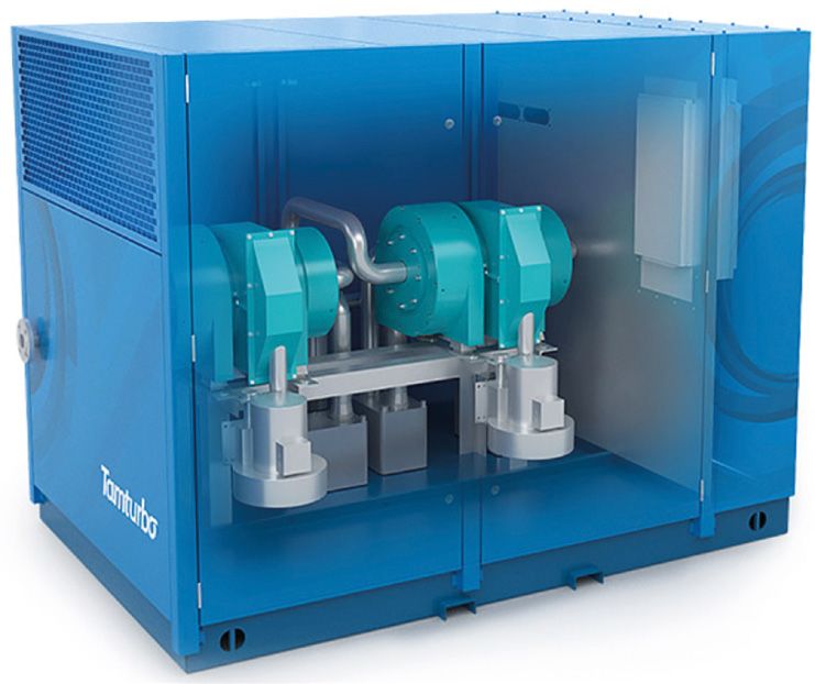
2016 Don Miller Award
Winners Highlight
the Versatility of
Flowmaster

F
        lowmaster is widely known for the
        variety of industries and applications
        that it can be used for. This is truly
        evident in the winning entrants of
the 2016 Don Miller Award for Excellence
in System Level Thermo-Fluid Design.
The three papers recognized, address
automotive engine cooling, two-phase
refrigeration processes, and passenger
comfort in rail transport. Additionally, the
entrants also showed the global reach of
Flowmaster with the winners coming from
India, Brazil, and China. We would like to
                                                  Figure 1. CAD drawing of Split Cooling System   Figure 2. Detailed Thermostat Drawing
take this opportunity to recognize their
excellent work.

 First prize went to Soujanya C, V Sundaram, &
 Sathish Kumar S of Chrysler India Automotive
 Pvt, Ltd. for their paper “Simulation of Split
 Engine Cooling System”

The important objective of this work was
to develop a Flowmaster simulation model
of split engine cooling system, which was
capable of predicting the coolant flow and
pressure drop across different engine speeds
and components. The new methodology
developed to model the engine coolant jacket
and two thermostats helped in achieving good
correlation of simulation results with that of
test.

The importance of split engine cooling system
is that, the coolant flow through a block
coolant jacket is stopped until the coolant
reaches certain temperature. This helps
the coolant reach a optimum performance
                                                                                                                      Figure 3. Flowmaster Model of
temperatures quickly. For this purpose, there                                                                         Split Engine Cooling System
are two thermostats available in the system.
This type of cooling system improves the          are fed to the tool. So care should be taken    Internal flow geometry details like coolant pipe
efficiency of the engine by increasing the        to get predictions near to bench test data.     flow diameter, pipe length, bend angle etc.
coolant temperature quickly to optimum level      The authors utilized several sources of         were extracted from the CAD and modeled
as soon as the engine starts.                     data including: CAD of the cooling system,      using simple flow components available in
                                                  performance details of the components, T-Stat   Flowmaster and component specific data
The performance prediction through any            hysteresis curves and engine performance        such as T-Stat hysteresis curves and pump
tool depends on the input parameters which        data.                                           performance curves were obtained from

10 mentor.com/mechanical
News
manufacturer data and brought into the model.
The main challenge involved in modeling
split engine cooling system is the modelling
of coolant jacket. Data from engine bench
tests was utilized. A flow sweep test was run
and the flows and pressures were obtained
across different pump speeds and coolant
temperatures, these results were also used in
the Flowmaster model
The Flowmaster model of split engine cooling
system was correlated against engine test
data and the predictions are within +/− 10 % Figure 4. Pump Flow Result Comparison Figure 5. Heater Flow Result Comparison
deviation.
The figures shows the comparison plots
and results between bench and simulation
predictions across split engine cooling system
at 76°C.
This innovative approach was developed
using Flowmaster which considers all the
restrictions involved in a complicated cooling
system like a split cooling system and
resulted in correlation of simulation results
with bench test data within 10% error. This
kind of simulation eliminates several bench
tests in analysis of engine cooling system
performance. This kind of approach in engine
development can reduce huge lead times
and costs in system development because
the simulation run time is a few seconds. The Figure 5. Schematic of Prototype Magnetic Refrigeration System
simulated model could be easily modified for
different scenarios and performance criteria of
the system could be easily evaluated in future
vehicle development.
First runner up prize went to Thiago Rubens
Vieira Ebel from the Federal University of
Santa Catarina, Department of Mechanical
Engineering, Brazil with his paper titled,
“Viability Analysis and Computational
Simulation of a Hydraulic Circuit for a
Magnetic Refrigeration System”. Truly a
unique application of Flowmaster in the area
of research. Figure 6. Initial Flowmaster Model of Prototype Magnetic Refrigeration System
Magnetic refrigeration is a cooling technology
based on the magnetocaloric effect which is
a magneto-thermodynamic phenomenon in The model was subjected to scenarios of great influence of the water hammer effect.
which a temperature change of a refrigerant different flow rates, operating frequencies and Conversely, for opening ramps larger than
material is caused by exposing the material opening ramps of the valves. It was concluded 15˚ (roughly 4.2% of the working period)
to a changing magnetic field. Flowmaster that the higher the flow rates, the stronger the the fluid finds less resistance to bypass the
was used to understand the water hammer dynamic events such as water hammer. regenerators during the switching time. This
effects that can occur in one such refrigeration effect tends to waste part of the flow but also
system. The operating frequencies proved not to decreases the water hammer effects. Relying
influence sensitivity of the hydraulic circuit. On on the results of different scenarios, the best
A simplified hydraulic system of the Brazilian the other hand, the variation of the duration overall performance is found associated to
prototype developed by Lozano (2015) was of the opening ramps demonstrated to have opening ramps between 8˚ and 15˚.
modeled by means of Flowmaster. The a key role on the whole hydraulic circuit. By
transient behavior of the absolute pressures modeling a similar behavior to the former Through the numerical simulation results at
and the mass flow rate through the regenerator rotary valves, when having opening ramps different operating conditions, a new layout for
beds was simulated. A deep understanding of smaller than 8˚ out of 360˚ (roughly 2% of the hydraulic circuit was proposed to improve
the dynamics of the circuit was gained. the working period), the circuit tends to have the performance of the refrigeration system.
mentor.com/mechanical 11Based on the obtained results in this work,
the most suitable solution is to include a
proportional returning valve before the high
pressure valves and after the low pressure
valves. Such a device would be capable of
absorbing the water hammer effects and to
make the flow through the regenerators’ beds Figure 7. Typical Water Hammer results in the System
smoother. Even though the system would
require higher pumping capacity, due to flow
bypass, an estimation of the novel hydraulic
circuit would have a COP of 1.34 and a
second law efficiency of η2nd = 9.55% (the
actual system had a maximum second law
efficiency of η2nd = 1.16%).
Second Runner up Award went to “Study
on the one-dimensional carriage and
ventilation system of high-speed train”
from Yifei Zhu, Yugong Xu, Xiangdong Chen Figure 8. Flowmaster Model of Redesigned Prototype Magnetic Refrigeration System
of the School of Mechanical Electronic
and Control Engineering, Beijing Jiaotong
University, Beijing, China.
Their work investigated the interaction of the
outside environment and the interior airflow
through the ventilation system of a high
speed train during operation. In past studies,
this interaction has been ignored resulting
in significant inaccuracies in the results.
The composition of the complex ventilation Figure 9. 3D CAD Drawing of Ventilation System of High- Figure 10. Flowmaster Network of Ventilation System of
system includes: air inlet, grill, controllable Speed Train Carriage High-Speed Train Carriage
dampers, ducts, air conditioning units, air
orifice, return air valves, and waste discharge
units. Due to the overall complexity and length
vs. the hydraulic diameter of the ducts, a
1D simulation with Flowmaster was the only
practical solution to the simulation problem.
Figure 9 is the 3D CAD drawing of the
ventilation of the high-speed train carriage. It
consists of a combination of fresh air ventilation
system parts, exhaust section and return air
Table 1. Comparison of Flowmaster Simulation Results Vs Actual Operating Point Values
section together.
bends and corners which have very small creative engineers from around the world are
Because the model is so complicated, a additional resistance relative to the long pipes finding new and innovative ways to use it to
simplification process was used to reduce the so they were omitted as well. solve their simulation and design problems.
complexity of the model. This included:
After these simplifications were made, the References:
1. The pressure protection valve is open in Flowmaster model was constructed as shown [1] C, S., Sundaram, V., and S, S., "Simulation
normal operation, so it was ignored, in figure 10. of Split Engine Cooling System," SAE
2. Air conditioning mixing box. This is just Technical Paper 2015-26-0196, 2015,
a confluence of container shaped like a Results of the simulation showed that the new doi:10.4271/2015-26-0196
Y-pipe, the drag coefficient is small, and outlet flow, exhaust port flow, return airflow, [2] Thiago Rubens Vieira Ebel, "VIABILITY
therefore considered as a modeling point and airflow rate of each branch meet design ANALYSIS AND COMPUTATIONAL
of convergence, and conditions and the calculation results are SIMULATION OF A HYDRAULIC CIRCUIT
consistent with the actual operating point of FOR A MAGNETIC REFRIGERATION
3. Because the study was only interested
the ventilation system, which demonstrates SYSTEM"Florianópolis - SC, February, 2016
in the airflow distribution and not the rationality and accuracy of the simulation
temperature the components of the [3] Yifei Zhu, Yugong Xu, Xiangdong Chen,
model. This modeling approach will be used to
air conditioning and heating units were " Study on the one-dimensional carriage
predict other environmental conditions inside
simplified to resistance elements based and ventilation system of high-speed train"
the train carriage.
on local resistance. International Power, Electronics and Materials
Engineering Conference (IPEMEC 2015)
The supply duct system lines consists mainly From these award winning papers it is easy
of long straight pipes with only a few individual to see the versatility of Flowmaster and how
12 mentor.com/mechanicalNews
FloEFD Technology Selected for New
French Automotive Lighting Master’s
Degree Program
M
entor Graphics Corporation Mentor’s FloEFD product, we are pleased ELS Chair at Institut d’Optique Graduate
has announced its partnership to be part of this much-needed master’s School. “FloEFD is uniquely positioned as a
of the Master's degree degree program,” stated Mohamed L’Baouch, best-in-class analysis product for automotive
program on automotive Director R&D at Automotive Lighting France. lighting design; as a result our graduating
Embedded Lighting Systems (ELS). “This program will help future automotive students will be able to step in and fulfill the
Three French universities, the Institut lighting systems designers understand the needs of the automotive industry immediately
d’Optique Graduate School, ESTACA and complexities and use the most progressive upon graduation.”
Strate Ecole de design, in partnership technologies to develop innovative lighting
with Renault, Peugeot-Citroen, Valeo solutions, while seeding the future with new For more information the embedded lighting
and Automotive Lighting, developed the talent.” Master's degree program and to apply, visit
ELS program. Mentor Graphics’ leading the website: http://embedded-lighting.com/
front-loading computational fluid dynamics The three universities will provide specialized formation-2/.
(CFD) FloEFD™ product has been selected courses: Institut d’Optique Graduate School
as part of the curriculum. will offer courses on optics and photonics; “We are honored to have FloEFD selected
ESTACA will provide transportation for this special automotive lighting master’s
As an industry-leading CAD-embedded engineering instruction; and Strate Ecole de degree program,” stated Roland Feldhinkel,
solution, the FloEFD product will provide design will cover design. The automotive general manager, Mentor Graphics
front-loaded CFD so students can evaluate industry partners supporting this master’s Mechanical Analysis Division. “Our market-
thermal performance early during the design program recognize the importance of this leading FloEFD product has proven to be
phase. As a fast, feature-rich, and easy-to-use specialty and the training will enable the an invaluable technology for our automotive
CFD tool, students will learn how to calculate students to master technical skills in the customers, and the students will be able to
condensation, meshing technologies, radiation emerging automotive lighting market. realize improved product quality, reliability and
modeling using Monte Carlo analysis, and “We are very pleased to be involved with this faster time-to-market when using this tool.”
apply reliable physics models to their designs. program since it fills a void for automotive
“As a sponsor of this program and a user of systems education,” stated Jean-Paul Ravier,
Mentor Graphics joins the
WBG-i consortium for Power
Electronics in Japan
F
ounded in 2013 by Professors power devices. All aspects of packaging for SiC and GaN based power electronics
Katsuaki Suganuma (pictured and reliability in the next generation of power is thermal dissipation. Mentor’s T3Ster™
right) and Tsuyoshi Funaki of electronics are being addressed. Already 34 transient thermal tester hardware is the
Osaka University in Japan, the industrial companies are involved in WBG-i most advanced technology in its field and
WBG-i (Wide Band Gap integration) consortium and several work groups have can contribute to understanding what is
power electronics consortium seeks been set up with regular workshops and going on in WBG semiconductors. There are
to pull together both academics and meetings. With developing links to ECPE standards for power LEDs already and we
industrialists from Japan and across the in Europe, and several North American believe that MicReD technology in Mentor
world in harnessing the possibilities of this and Asian partner organisations, WBG-i Graphics’ Power Tester can help in developing
new technology and in dealing with its consortium is becoming a truly international power cycling standards for WBG power
challenges. driver for change. Speaking about the electronics.”
recent addition of Mentor Graphics to the
WBG semiconductor materials such as SiC consortium, Prof. Suganuma said: Reference:
and GaN allow power electronic components WBG-i consortium website: http://wbg-i.jp/en/
to be smaller, faster, more reliable, and much “We are glad that Mentor Graphics is joining
more efficient than conventional silicon based WBG-i consortium. One of the key issues
mentor.com/mechanical 13Optimizing a
NASCAR Racing
Machine
Voxdale collaborate to engineer a
champion car using FloEFD
By Mike Gruetzmacher, Technical
Marketing Engineer, Mentor Graphics
N
ASCAR is the most popular
motorsport competition in
the USA. The three largest
racing-series are the Sprint
Cup Series, the Xfinity Series, and the
Camping World Truck Series. NASCAR
sanctions over 1,500 races at over
100 tracks in 39 of the 50 US states,
as well as in Canada, and its races are
broadcast in over 150 countries.
Initially only modified large scale series
vehicles were used for NASCAR. Today’s
NASCAR vehicles are racing cars with a
V8 engine and up to 800 horsepower, but
restricted in compliance to the applicable
regulations. Only the car body silhouette
resembles a series car. The cars are
subjected to strict regulations, for example
a limited size for the rear spoiler, the chassis
material thickness or allowed production
processes for the engine cylinders. It is
normal practice that winning team cars
are dismantled by NASCAR officials after a
race to check for any irregularities. The car
performances are almost equivalent. There
are only a few rare opportunities to gain
any technical advantage. This leads to the
teams needing to find ways of making small
gains wherever they can to improve their
performance.
14 mentor.com/mechanicalAutomotive
mentor.com/mechanical 15The popularity of NASCAR racing is increasing
in Europe, with the NASCAR Whelen Euro
Season. NASCAR rules and standards are
adopted in the series but the cars are built
specifically for European tracks and the
horsepower is restricted to 450 hp. One of
the most successful European race drivers
is Anthony Kumpen from Belgium. He is the
overall winner of the 2014 NASCAR Whelen
Euro Series season. His huge success in
Europe qualified Anthony to compete in the
US NASCAR K&N Pro Series East. Today
he combines the NASCAR championship in
Europe with races in the USA.
We met Anthony Kumpen together with Koen
Beyers, CEO of Voxdale BVBA, a successful
CFD engineering consultancy, to see what
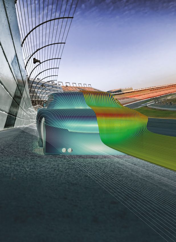
CFD could do to improve their car. Voxdale Figure 1. Velocity Streamlines on Body Surface and Isosurface around the Car Body
collaborate to engineer Anthony’s team cars
using Mentor Graphics’ FloEFD.
Anthony explains that there are many
aspects to be considered for a racing driver,
“There is the driving aspect which is one of
the real interesting parts but there are also
all the technical details to be optimized. I’m
working with engineers and mechanics.
There is a lot more than just driving fast in
a car. That’s what racing is all about. Being
a racing driver everybody thinks I spend all
the time in the car but actually I spend 80%
of my time in meetings with my engineers,
with my chief mechanics. Engineering is
something we have to study every day in
order to be a good driver.”
One field Anthony and his team are particularly
interested in, is aerodynamics. Since the
team does not own or have access to a wind
tunnel, like an F1 team would have, they
had to find another way to analyze their car’s
performance. So they teamed up with Koen
and the Voxdale team, who are experienced
Figure 2. Anthony Kumpen (left) and Koen Beyers (right)
in racing aerodynamics. Voxdale Engineers
began working on this NASCAR project
by conducting CFD simulations in Mentor
Graphics’ FloEFD 3D Simulation software.
“The main goal of the partnership was to get
insights in the behavior of the car. So when
we got involved in the NASCAR project with
Anthony the first thing we had to do was to
look into what was actually possible to do,"
Koen Beyers, Voxdale CEO explains.
The NASCAR series is a closed racing
series with a very tight rulebook and strict
regulations. For instance, the body work could
be changed nor could the manifolds or engine
parts. Anthony’s team and Voxdale decided
to analyze the car’s aero-mapping and overall
behavior. They also investigated the internal
flows, the flows underneath the body, and Figure 3. Pressure Coefficient Cp
16 mentor.com/mechanicalAutomotive
the hood. Furthermore they optimized the
cooling of the brakes and the exhausts. As
preparation for the simulations the car model
was set up in FloEFD for PTC Creo. The
modeling of the geometry took around three
days, the FloEFD simulation setup took about
a day. The engineers conducted around
ten simulations directly within the PTC Creo
environment which took about two weeks
including post processing. The results of these
quickly prepared and evaluated simulations
were used for rapid optimizations as the
regulations and schedules disallow long
predevelopment phases.
“At one point, we saw the effect of a specific
riding height combined with an explicit rake Figure 4. : Velocity Profile underneath the vehicle
angle resulting in a drag reduction of 0.8%.
Over one lap at Brands Hatch, with this car
with this power, this buys you 0.2 second. An
important leap in a closed racing series”, Koen
illustrates.
“It is very cool to see the car racing on track,
that you analyzed the car and helped the team
to give an even better performance” says
Patrick Vlieger, Engineer at Voxdale.
“There are a lot of different aspects on
aerodynamics that are important for racing.
Sometimes you want to have the maximum
downforce, sometimes you want to have as
little as possible downforce and make the
car run really smooth. With all the data the
Voxdale engineers gained Anthony’s team and
his engineers tried to improve the cars on the
track and so far it’s working really well.” as
Anthony confirms.
Anthony Kumpen, “With FloEFD we could
do a lot of tests and improvements of the car
which helped us a lot. We are winning a lot of
races. It’s all about the details of racing and Figure 5. Velocity Profile underneath the Car Body and Wheelhouses
finding the right partners and we are really
happy to do this with Voxdale.”
References
http://www.nascar.com
https://en.wikipedia.org/wiki/K%26N_Pro_
Series_East
https://en.wikipedia.org/wiki/NASCAR
http://www.formula1-dictionary.net/map_aero.
html
http://www.f1buzz.net/2009/02/17/what-is-
aero-mapping/
https://www.reference.com/sports-active-
lifestyle/much-horsepower-nascar-stock-car-
eb5f6a334398b967#
http://auto.howstuffworks.com/auto-racing/
nascar/nascar-basics/nascar-engines1.htm
http://www.racingblog.de/nascar-faq/
Figure 6. Velocity Profile underneath Car Body and Pressure Distribution the Spoiler
mentor.com/mechanical 17How To...
Create FloMASTER™ N-Arm Components using FloEFD™.
By Robin Bornoff, Market Development Manager, Mentor Graphics
A Simulation Based
Characterization Workflow
The new FloMASTER V8 N-Arm
component allows for multi-arm (up to
60) junctions to be modeled in a circuit.
For applications such as automotive
thermostats and pump housings,
multiple inlets and outlets interact with
each other to produce complex pressure
drop vs. flow rate relationships. Instead
of relying on the assumption that such
arm pairs can be modeled as discrete
parallel losses, FloEFD can be used to
characterize the combined effects that
each arm has on the others. The results
of such a characterization are imported
into FloMASTER whereupon an N-Arm
component is created.
To introduce the workflow, let’s consider
a simple five arm pipe junction. This is
modeled in FloEFD by applying boundary
conditions to five faces. A combination of
flow and pressure boundary conditions can Figure 1. FloEFD five Arm Geometry Showing Boundary Conditions
be set. However (at least) one face needs
to have a pressure boundary condition, this
face will be considered the reference arm
in the subsequent calculation of pressure
drops. The working fluid is set as water and
the model meshed using default settings.
A new ‘characterization’ parametric mode
has been added to FloEFD solely for
the ability to create N-Arm components
for FloMASTER. Ranges over which the
Figure 2. Characterization Range Extents
geometry is to be characterized is first
set for all non-reference arm boundary
conditions. These might be mass flow, ensures that the characterization will be response surface fits the solved points is
volume flow, velocity or pressure ranges. fluid independent, i.e. the fluid used in shown in the scenario table.
FloEFD need not be the same fluid used in
A user defined number of computational FloMASTER. The response surfaces may be visualised;
experiments are then created that set 2D plane response surface sections are
random, but equally spaced, combinations To consider the effects that all arms have on shown. Slider bars can be used to alter the
of the boundary condition values, the pressure drop between an arm and the parameters of the dimensions not included
throughout the characterization space. reference arm, the following relationship has on the displayed axis. This provides a
Each experiment is shown as a column in to be determined: graphical indication of the relationship
the Scenario tab. These models can then between the pressure drop (between an arm
be solved, either on the local machine, or Dimensionless Pressure Drop and the reference arm) and the flow rates in
concurrently utilising a network. Arm i-Ref Arm
= f(Dimensionless Mass FlowArm 1, all the arms.
Dimensionless Mass FlowArm 2 …
When solved, FloEFD automatically extracts Dimensionless Mass FlowArm N-1) Should the error of the response surface
a dimensionless mass flow value for each fit be considered too large, additional
arm (akin to the Reynolds number) and This is done using response surfaces. For experiments can be created and solved and
a dimensionless pressure drop between each dimensionless pressure drop, an N-1 the response surface regenerated, until such
an arm and the reference arm (akin to dimensional response surface is created. time as the error falls below acceptable
a loss-coefficient). Non-dimensionality The error showing how well, on average, the levels.
18 mentor.com/mechanicalThe response surface models, together with Figure 3. Scenario of Solved ‘Computational’ Experiments
a 3D interactive view of the geometry, are
then exported to the file system in a .flonarm
file. This file is imported into FloMASTER
whereupon an N-Arm component is
created. The N arms are then connected
to the FloMASTER circuit and solved in the
usual way.
Summary
This simulation based characterization
Figure 4. Dimensionless Press Drop Response Surface Creation
workflow enables FloEFD to be used to
capture all complex interacting 3D flow
effects, incorporated into the behavior
description of the N-Arm component. For
multi-arm geometries that are complex to
extend where errors may be introduced
using collections of existing FloMASTER
components, or to extend the operational
range of existing FloMASTER components,
FloEFD used together with FloMASTER
provides unique opportunities.
Figure 5. Response Surface Visualization
Figure 6. N-Arm Component in a FloMASTER Circuit
mentor.com/mechanical 19Air Dynamics
Simulation of the
Tamturbo Oil-Free Air
Turbo Compressor
By Timo Pulkki, Mihail Lopatin, Tamturbo Oy, Tampere, Finland & Alexandr Nikulin, Axis
Engineering (Mentor Graphics distributor), Saint Petersburg, Russia & Tatiana Trebunskikh,
Mentor Graphics, Moscow, Russia
N
owadays to be competitive
in the air turbo compressor
industry, the company must
provide high performing
hardware with the lowest life cycle
cost. In most cases to achieve such
characteristics the company has to
use a range of innovative technologies.
Tamturbo Oy, was founded in 2010 in the
Tampere region, the birthplace of several
compressor innovations, has achieved
their goal of transforming their view of oil
free technology into a worldwide success
story. They are fully committed to
delivering solutions that bring the highest
life cycle value to their customers.
Performance prediction of the prototypes
of air turbo compressors is one of critical
questions during the design process. As
soon as such predictions are available, the
design engineers are able to optimize the
device, taking into account a number of
factors like the cooling of the compressor
stages or cooling of the electrical engine
driving the compressor. Moreover all issues
with new design should be discovered as
soon as possible before hardware testing,
to reduce development time and cost. Figure 1. The Tamturbo compressor
The required changes can be minor or
major for larger parts. Without dependency
on the scale of the changes, a deeper more effective in investigating directly, during approach usually requires transferring
understanding is required into processes the product design process as an integral geometry from a CAD system to CFD
inside the particular parts as well as the part of the product lifecycle management software, via different exchange formats,
whole device. This is the reason Computer- (PLM) in the early development stages. where some issues with geometry can
Aided Engineering (CAE) software and There are several approaches in CFD occur. Issues such as cleaning and healing
Computational Fluid Dynamics (CFD) including traditional and frontloading. In geometry to make it suitable for mesh
software in particular are so popular in the addition to relying on the vast knowledge creation and manual mesh generation with
modern industrial world. CFD in particular is and experience in CFD, the traditional focus on boundary layers. Investigations
20 mentor.com/mechanicalProcess
of a wide range of designs using such an
approach is very time-consuming and as
a result only a few particular cases are
examined by CFD experts after all changes
are made by the design engineer.
The frontloading approach presented in
Mentor Graphics’ FloEFD™ tool, is intended
for use in the early design development
stages by design engineers. There are
two main principals in FloEFD: direct use
of native CAD as the source of geometry
information, and a combination of full three-
dimensional CFD modeling solving Favre-
averaged Navier-Stokes equations with
simpler engineering methods in the cases
where the mesh resolution is insufficient for Figure 2. Ring creation in the Circumferential Averaging Rotation Approach
direct simulation.
To overcome a traditional CFD code
restriction of having a very fine mesh density
near walls in a calculation domain, FloEFD
describes boundary layer, with the “Two-
Scale Wall Functions” method including the
near wall functions and the sub-grid model
of the boundary layer.
For the simulation of the compressor, the
rotation model should be used. There
are two local rotation models in FloEFD
– circumferential averaging and sliding.
The circumferential averaging approach
is employed for calculating transient or
steady-state flows in regions surrounding
rotating solids, which are not bodies of
revolution (e.g. impellers, mixers, propellers,
etc). To connect solutions obtained within
the rotating regions and in the non-rotating Figure 3. Sliding Rotation Approach
part of the computational domain, special
internal boundary conditions are set
automatically at the fluid boundaries of
the rotating regions. The rotating region’s
boundaries are sliced into rings of equal
width and the values of flow parameters,
transferred as boundary conditions from
the adjacent fluid regions are averaged
circumferentially over each of these rings.
The sliding rotation model produces a time-
accurate unsteady solution of the flow fields,
where the rotor-stator interaction is strong.
The sliding technique takes into account
the relative motion between stationary and
rotating regions. Rotor and stator control
volume (CV) zones are connected with each
other through "sliding interface". During the
calculation, zones linked through "sliding
interface" remain in contact with each other.
The sliding interface has CVs on both sides
and as a consequence each face of the
sliding interface has two sides belonging
to both rotor and stator zones. All these
techniques allow FloEFD to be used for the
calculation of air turbo compressors. Figure 4. The Mesh of the Compressor Model
mentor.com/mechanical 21This article shows a great example of the two
stages of oil free compressor investigation,
completed by Tamturbo Oy with support
from Axis Engineering.
For analysis, the full assembly of the
compressor was used, the construction
of which includes several contours:
compressor flow area, and several
cooling contours. Each contour includes
components manufactured from different
materials, such as titanium steel or
aluminum, which were chosen based on
the results of the preliminary calculations of
thermal loads and strengths of the various
parts of the compressor.
The geometry of flow area has been
determined by required compressor
characteristics and has a very complex
internal structure. The CFD analysis of the
compressor, where final pressure rise ratio
was calculated, allows for the assessment
of air temperature rise. To decrease the
temperature of the compressor’s body,
Tamturbo engineers added the cooling Figure 5. Temperature Distribution in the Longitudinal Section of the Compressor
system for the compressor with a complex
internal structure.
All geometry features of the compressor,
presence of the rotating parts and special
requirements for temperature in some critical
places like bearings, volutes, shaft and so on,
predetermined mathematical models which
were needed for the analysis.
The turbulence model used in the analysis
can detect a flow regime and switch the
mode between laminar and turbulent
automatically. This solver is unique and
allows an engineer to obtain a solution inside
narrow channels even on a coarse grid. The
Figure 6. Stage 1. Temperature Distribution in the Cross Figure 7. Stage 2. Temperature Distribution in the Cross
calculation was made taking into account Section of the Compressor with Streamlines Section of the Compressor with Streamlines
conjugated heat transfer, where heat transfer
equations were solved in solid bodies. The
radiation model has been disabled due to values instead of using the FloEFD feature Initially homogeneous structured mesh was
relatively low temperatures. emulating a real Joule heating process. created on the entire geometry, where the
number of cells along the main axis of the
In the analysis of the flow, to consider the Simulation of conjugate heat transfer process compressor did not exceed 90. The number
rotation of the impellers, special rotating for all zones and units of the compressor, of cells for the other axis was chosen in the
model “sliding” was used, which helps allowed for the investigation of their mutual way that the final size of the basic cells was
to predict characteristics of any type of influence and predicting the thermal state of similar in all three dimensions. After creating
turbomachines with better quality. the compressor components. the basic mesh, some local regions for
better mesh resolution around compressor
As boundary conditions for the airflow inside The most important parameters under impellers and in the bearing’s area were
the compressor were specified so were investigation were air temperature before the added. Additionally mesh generator settings
the conditions for pressure at the volutes bearings the volute and the shaft temperature. were specified to allow for automatic
outlets, mass flow rate at their inlets, and Mainly bearings work properly when their detection of the narrow channels and further
shaft rotating speed. For cooling paths, temperature is lower than 100-120°C, but splitting mesh in these areas. As a result the
pressure difference between inlet and outlet on the other hand the temperature of the total number of cells in the entire two-stage
boundaries was determined. To simplify the compressed air can be higher than 200°C. machine was approximately 4.9 million.
thermal analysis of the engine and the shaft, And of course every calculation has to predict
a heat emission process was simulated by the compressor pressure rise ratio for the The analysis was run in the transient regime
adding heat sources with constant power required mass flow rate range. on the usual workstation for CFD calculation:
22 mentor.com/mechanicalYou can also read