Fusion Electricity
A roadmap to the realisation of fusion energy
                                     Annexes
←
→
Page content transcription
If your browser does not render page correctly, please read the page content below
Fusion Electricity
A roadmap to the realisation of fusion energy
Annexes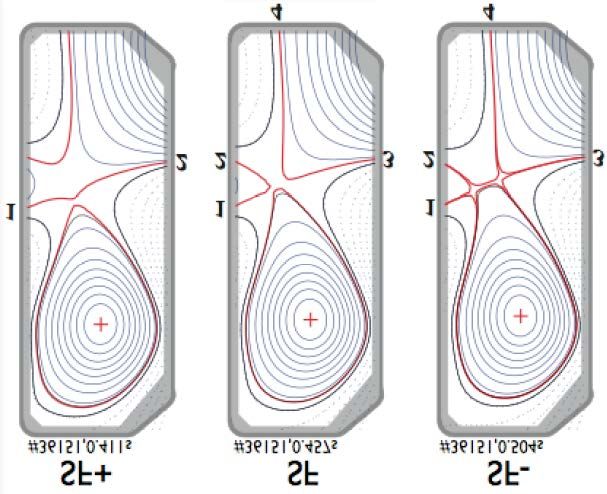
Table of content

Annex 1.    Mission 1 - Plasma regimes of operation of a fusion power
            plant
Annex 2.    Mission 2 - Heat and particle exhaust
Annex 3.    Mission 3 - Neutron resistant materials
Annex 4.    Mission 4 - Tritium self-sufficiency and fuel cycle
Annex 5.    Mission 5 - Implementation of fusion safety aspects.
Annex 6.    Mission 6 - Integrated DEMO design and system
            development
Annex 7.    Mission 7 - Competitive cost of electricity.
Annex 8.    Mission 8 - Stellarator development
Annex 9.    Education and training needs in support of the EU fusion
            roadmap
Annex 10.   Opportunities for basic research
Annex 11.   Resources and implementation scheme
Annex 12.   Industrial involvement in the realization of fusion as an
            energy source
Annex 13.   International collaborations for the development of Fusion
            Energy
Annex 14.   Risk Register (internal use only)
Annex 15.   Work Packages (internal use only)
Annex 16.   Roadmap Gantt chart (internal use only)

                                                                         2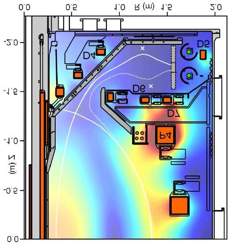
Annex 1. Mission 1 - Plasma regimes of operation of
a fusion power plant
Authors: L. Horton (EFDA CSU), G. Sips (EFDA CSU), R. Neu (EFDA CSU)

1.1 Short description.
In a fusion power plant, plasma regimes need to ensure a high fusion gain Q
(Q=Pfus/Paux). The Lawson criterion sets a limit on the nτE product (with n the density
and τE the energy confinement time) to achieve a given fusion gain. The energy
confinement time is determined by plasma turbulence that has been progressively
controlled by developing of more advanced regimes of operation. Our present
understanding of transport processes in plasmas shows that the nτE product increases
with the power plant dimension.

A number of regimes of operation have been developed in tokamaks over the years
(see box), which are at varying degrees of readiness with respect to application in the
fusion reactor. The Type I ELMy H-mode is the most developed regime and forms the
basis for standard operation in ITER. However, a few points still require a
demonstration.

Tokamak plasma regimes
L-mode: In its simplest mode of operation, the energy and particle confinement in a
tokamak is limited by turbulence across the entire minor radius (rather than binary
collisions leading to so-called neoclassical transport). The corresponding regime of
operation has, relatively speaking, low global confinement and is called the L-mode.
H-mode: In magnetic configurations with an X-point geometry limiting the region of
confined plasma and above a certain input power, the turbulence dominating the edge
thermal and particle transport is spontaneously suppressed, leading to an increase in
the global confinement of approximately a factor of two. This high confinement
mode of operation is called the H-mode. Indeed the energy and particle content of the
H-mode edge is so good that the plasma parameters typically increase until a stability
limit is reached. Several variations on the H-mode regime exist, distinguished by the
stability mechanism that is employed to achieve steady-state or quasi steady-state
(stationary averaged over limit cycles) plasma conditions.
- Type I ELMy H-mode: The most widely studied steady H-mode is limited by
   discrete edge localised modes (ELMs). This is the H-mode regime with the highest
   confinement and is the basis for predicting performance in ITER. The main open
   issue is that the pulsed power load on first wall components due to unmitigated
   Type I ELMs is too large for ITER and a fusion power plant.
- Type II ELMy H-mode: At high plasma density and with strongly shaped magnetic
   configurations, the small, high frequency ELMs gradually replace Type I ELMs,
   eventually completely replacing large ELMs. To date, this regime has only been
   achieved at high density and thus at high edge collisionality. The combination of
   high density and low collisionality required for a reactor can only be achieved at
   large machine size. The present strategy is to base ITER on regimes, such as the
   Type I ELMy H-mode, which can be achieved at both high density and low
   collisionality (separately) in present machines. On the other hand, experiments in

                                                                                     3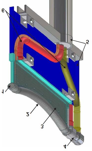
ITER with regimes such as the Type II H-mode will provide a definitive test of the
   their reactor-relevance.
- Type III ELMy H-mode: The simplest method of ELM mitigation in present
   machines is gas puffing to increase the resistivity of the plasma edge to the point
   that the resistive stability limit is below that of the ideal limit. In this circumstance
   small Type III ELMs appear with much lower pulsed power loads on the plasma-
   facing components and global confinement intermediate between that of the L-
   mode and the Type I ELMy H-mode.
- QH mode: At low plasma collisionality and with external control of the torque
   introduced to the plasma, it is possible to generate a harmonic oscillation in the
   edge of the plasma that provides sufficient energy and particle transport achieve
   stationary conditions below the ideal edge stability limit and thus without ELMs.
   This is referred to as a quiescent H-mode or QH mode. Tests of this regime in
   ITER with high density in combination with low collisionality and with the lower
   available external momentum sources will determine the feasibility of applying
   this regime in a fusion power plant.
AT modes: To achieve truly steady-state operation in a tokamak the plasma current
must be driven without use of the central solenoid for inductive current drive. Limits
on recycling power in a fusion power plant mean that a significant fraction of the non-
inductive current drive must be self-generated. The self-generated current scales with
the normalised plasma pressure gradient, whose radial profile must be to a large
extent aligned with the required total current profile for the regime. Calculation and
proof-of-principle experiments show that manipulation of the plasma current profile
can be used to improve the core plasma confinement and thus the pressure gradient
there. There are several variants of plasma current profiles presently under
investigation with the family of regimes collectively known as advanced modes of
tokamak operation or AT modes. While it is possible to produce such regimes with
either an L-mode or an H-mode edge, it is likely that the confinement advantage of
the H-mode will mean that AT modes will be variations of H-modes, with the pros
and cons of the various edge stability mechanisms discussed above.
Hybrid modes: As stated above, it has been possible to improve confinement by
manipulating the plasma current profile. While this has not yet been developed into a
fully non-inductive, advanced mode of operation, the technique has been used in
regimes that should allow in ITER a combination of higher performance and longer
pulse length. As these regimes are intermediate, in the sense of the fraction of self-
generated current, between conventional H-modes and advanced modes of operation,
they are referred to as hybrid modes of operation.

Specifically, plasma regimes of operation in a fusion reactor need to integrate:
   1. Burning-plasma conditions in which fusion generated alpha particles are the
       dominant heating mechanism;
   2. High density for achieving high fusion power and reactor-relevant values of
       the neutron wall load (~1-2MW/m2);
   3. Large radiated power from a mantle surrounding the hot plasma core (to
       reduce the power conducted to the divertor and achieve acceptable divertor
       heat load);
   4. Avoidance/mitigation of off-normal events (ELM, disruptions);
   5. Diagnostics and actuators compatible with the reactor environment.

                                                                                          4
Requirements 1-5 are common to all magnetic fusion concepts. Plasma regimes that
can achieve these conditions for long pulses (~8h in a Fusion Power Plant (FPP),
relying in part on plasma current driven inductively by the tokamak’s central
solenoid) have been already demonstrated in tokamaks and could be the basis for a
conservative DEMO reactor. Fully steady-state plasma regimes can also be produced
in tokamaks but they require to integrate also:

   6. High values of the plasma beta and a large fraction of self generated bootstrap
      current;

As these non-inductive regimes of operation require more advanced control of the
plasma and operation closer to stability limits, Requirement 5 for reactor-
compatibility of diagnostics and actuators will be more restrictive.

The stellarator configuration is not prone to disruptions and is intrinsically steady-
state but it has to pass a development path that makes it not suitable for DEMO on the
time scale considered here. Its development path, described under Mission 8, aims at
validating the stellarator as an option to the tokamak by the time of the market
penetration of fusion.

1.2 Critical aspects for reactor application.
Burning plasma. In present experiments, the level of plasma heating and its radial
profile can be to a large extent controlled externally. Alpha particle heating, on the
other hand, is determined by the plasma density and temperature. Thus, a reactor will
be a self-organized system with reduced control of and by plasma heating. In addition,
fusion-generated alpha particles can drive collective instabilities that can limit plasma
performance.
High-density operation. In tokamaks, the edge plasma density cannot be increased
above an empirical limit (the Greenwald density limit). The investigation of the origin
of the limit and of possible ways to overcome it is an active field of research. One
option being tested is the use of plasma density peaking to simultaneously respect the
Greenwald density limit for the edge plasma whilst increasing the core density so as
to maximise the fusion yield. If reactor relevant regimes with n>nG cannot be
achieved, high densities could be achieved by operating at higher plasma current and
correspondingly higher toroidal magnetic fields (requiring a further development of
super conducting magnet technology). For the purposes of the conservative DEMO,
no credit for trans-Greenwald densities is taken, with research into accessing higher
density as a high priority given the large potential gains in a FPP.
Large radiated power. The regimes of operation in present machines typically
achieve high confinement for values of the power radiated from the region inside the
separatrix (core radiation) below 30% of the input power. In a reactor the radiated
fraction from the core will be larger than 70%. Within the scope of Mission 1, the
critical issue is how to develop regimes with a sufficiently large fraction of heating
power radiated from the core without reducing the energy confinement time and
avoiding thermally unstable regimes.
Avoidance/mitigation of off-normal events. ITER can tolerate a few disruptions and
the assumed disruption rate is in line with the present JET experience. However, a
reactor should be almost disruption free. Thus, tokamak plasma scenarios must
include specific provisions for disruption avoidance and their early detection, control
and mitigation. In addition to disruptions, unmitigated Edge Localized Modes (ELMs)

                                                                                       5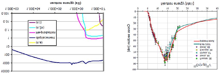
will produce unacceptably high thermal loads on the plasma facing components and
must be suppressed or reduced to very low amplitude.
Diagnostics and actuators reactor compatible. In a FPP, diagnostics have to operate
in conditions that will limit the applicability of present systems: limited view,
radiation hardness, simple design for reliability. For the actuators, a selection of the
H&CD systems will be necessary on the basis of their capability of fulfilling DEMO
needs (source, launcher, CD efficiency).

If steady state operation are considered the following points should be also addressed.

High-β AT regimes. A steady-state electricity output can in principle be achieved
with pulsed plasma operation provided adequate heat storage is available.
Nevertheless, steady state plasma regimes may have the benefit of reduced reactor
size, lower fatigue of core components and lower cost of electricity. Steady-state
operation in tokamaks requires accessing regimes at high beta that are characterized
by a large fraction of the plasma current generated through the bootstrap mechanism.
Since the plasma is close to stability boundaries, these regimes are more prone to
disruptions and require a number of sophisticated diagnostic, control and actuator
mechanisms. The limitation to reactor-compatible diagnostics and actuators discussed
above is thus likely to be more restrictive for advanced modes of operation.
Compatibility between high CD fraction and divertor operation. Even in AT
regimes, part of the plasma current must be driven by external current drive methods.
The efficiency of plasma current drive increases with plasma temperature and
decreases with density and thus is inversely proportional to the square of the plasma
density at constant pressure. Divertor operation in a reactor, however, requires high
edge plasma density values. Thus, a compromise must be found and the window in
plasma density for AT regimes in a FPP operation will be restricted.

1.3 Level of readiness now and after ITER.
The achievement of Q=10/300s target on ITER relies on the Type-I ELMy H-mode
regime at moderately high plasma density (85% of the Greenwald limit), energy
confinement time in line with the ITER98y2 scaling, a moderate values of beta (βN≤2)
and about 40% of the heating power radiated from the region inside the magnetic
separatrix (if partially detached divertor operation are assumed). This regime is well
qualified. Indeed, ITER demonstration discharges have been successfully performed
in several tokamaks. However, the regime’s use on ITER is subject to the
suppression/mitigation of Edge Localized Modes, for which solutions (pellet pacing,
resonant magnetic perturbations, etc.) have been already tested in medium size
devices (a test in JET-size machine is still awaiting) and the confirmation that alpha
particle collective modes do not limit plasma performance in this regime, as indicated
by some theoretical studies. Verification of the effectiveness of alpha heating is a
prime goal of ITER.

ITER also aims at demonstrating a fully steady–state scenario at Q=5. In order to
meet this goal, the steady state scenario should achieve a confinement about 50%
above the ITER98y2 scaling. Such a regime has not yet been demonstrated in present
tokamaks although both theory and experiment suggest that it might attainable with
appropriate tailoring of the plasma current profile. An intermediate step, a ‘hybrid’ of
the conventional ELMy H-mode and a fully non-inductive advanced mode of
operation has been demonstrated in several machines, providing a confinement

                                                                                      6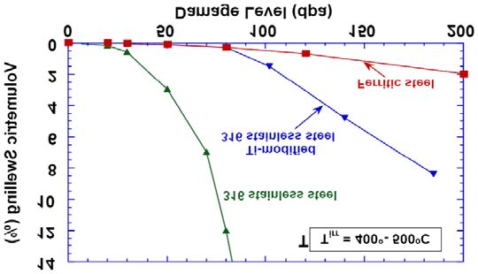
improvement of ~20%. This hybrid regime could be prototypical to those of a pulsed
tokamak reactor provided large radiated power is simultaneously achieved.

Development of fully steady-state regimes requires a similar effort to that of the
1980s and 90s leading to the qualification of the ELMy H-mode (the H-mode was
discovered in 1982 and the definitive confinement scaling published in 1998). The EU
strategy is based on an intensive campaign of regime identification and optimisation
on medium-sized tokamaks (both in the EU and outside), possibly supplement by
initial size-scaling experiments in JET, and then a large machine test in JT-60SA in
the 2020s. On the same time scale as was required for the conventional regime, it is
hoped to provide a qualified regime for testing in Phase 2 of ITER operation (2030s).
Given the time scales and the risks associated with designing to a plasma regime that
does not yet exist, a conservative DEMO, with construction starting in 2030, should
be based on the conventional or hybrid regime. Should DEMO be delayed for some
reason, the Phase 2 test in ITER would provide definitive input as to whether an
advanced regime of operation can be incorporated in DEMO.

In summary, ITER will extend the present qualification of the plasma regime of
operation to burning plasma conditions. ITER can demonstrate whether full
avoidance/control/mitigation of disruptions is possible at reactor scale. A fusion
reactor is presently foreseen to be a relatively limited extrapolation in linear
dimension from ITER and so with a similar physics. Thus ITER should be able to
complete Mission 1. In this regard, it should be noted that ITER, in order to fully
address the divertor issues discussed in Mission 2, will have to go beyond the
achievement of the headline missions of Q=10 (inductive) and Q=5 (steady-state). In
particular, it will be necessary to investigate the compatibility between high radiation
and high confinement up to the maximum possible radiated power fraction and taking
advantage of the proposed upgrades to reach the maximum possible level of input
power.

1.4 Main risks and risk mitigation strategies.
From the considerations presented above it is clear that the achievement of Mission 1
is strictly linked to the success of ITER. The ITER Organization (IO) has made a
detailed analysis of the risks to ITER Phase 1 operation and has identified the main
R&D needs to mitigate those risks. The top ITER risks form the basis for the first nine
entries in the Mission 1 risk register. These risks have then been supplemented by
risks that are expected to be addressed in ITER – essentially regime integration at the
reactor scale and burning plasma physics – and by a few risks specific to the step from
ITER to DEMO.

The risk register has been used to develop a series of high-level work packages for
risk mitigation. Generic machine and subsystem requirements are given for each
package, e.g. ITER/DEMO magnetic geometry, metallic plasma-facing components,
machines of varying size, integration into ITER plasma regimes. These requirements
can be compared to list of tokamak capabilities given in Table 1. Risk mitigation of
the conventional modes of operation foreseen for ITER Phase 1 and the conservative
DEMO it expected to be provided primarily by JET in this decade and then ITER in
the 2020s. For advanced modes of operation, the development path is via medium-
sized tokamaks in this decade, JT-60SA in the 2020s and ITER Phase 2. Besides JET,
in Europe most of the relevant capabilities are available in ASDEX Upgrade, which is

                                                                                      7
expected to play an important role during Horizon 2020. In addition, international
collaborations on machines such as DIII-D, KSTAR and EAST would provide
valuable additional information to EU understanding.
To accomplish all of the objectives of the work packages, some machine upgrades are
required. The ITER heating & current drive systems will have to be upgraded in order
to provide the plasma current profile control required for testing advanced modes in
Phase 2. Preparing the options for this upgrade will require some investment in the
present decade. In addition, while the use of tungsten armour for all plasma-facing
components has been successfully tested in ASDEX Upgrade and is the only presently
known solution for DEMO, it is felt that the step from a medium-sized tokamak to
DEMO is too large and that a test of an all-tungsten wall in a larger machine is
required. Ideally, this test would take place in ITER and the IO is presently evaluating
the feasibility of changing the armour material in ITER. If that proves not to be
possible, a tungsten test might be done in JT-60SA, provided agreement can be found
with our Japanese colleagues. As a third option, a full tungsten wall could be tested in
JET in the early 2020s. This would have the advantage of providing an earlier test but
would be with inertially-cooled components and short plasma pulses.
While the work packages are milestone-based, it is recognised that theory &
modelling must play a key role in the development of the plasma regimes for a FPP
and it is intended that a significant fraction of resources be allocated to this type of
work. Project aimed at better physics understanding might address topics such as the
L-H transition, electron transport, the plasma response to externally applied non-
axisymmetric fields and the physics of ELMs.
1.5 Options for Implementing the Work Packages and/or Gaps.
Virtually all of the work packages require operation in a diverted tokamak with as
close as possible to the ITER/DEMO/FPP. The main machine parameters and
capabilities for several such tokamaks, in the EU and outside, are listed in Table 1.1.
Metal Plasma Facing Components (PFCs) are an essential component of Work
Packages 1.1, 1.7-9, 1.14, 1.18 and 1.21 (presently AUG, C-Mod and JET, in the
future, EAST, KSTAR and ITER). In addition, the regime development in Work
Packages 1.3 and 1.20 can only be considered complete if proven in conjunction with
a metal wall. Size scaling is an important element of Work Packages 1.1, 1.3-7, 1.9,
1.13, 1.14, 1.18 and 1.20. In addition, large machines are specifically required for
(elements of) Work Packages 1.4, 1.10, 1.12, 1.17 and 1.21. For these reasons, ITER,
JET (up to 2020) and JT-60SA (post-Horizon 2020) have unique roles to play.
Overall, integration of the various work packages into self-consistent scenarios is
crucial and under-represented in the attempt to divide the crucial issues into separate
items. The present EU strategy, as set out in the Facility Review, must be to focus on
a few, well-equipped machines including appropriate upgrades to address this need to
integrate.
For inductive modes of operation, the main remaining issue is proving the
compatibility of the regime with the first wall requirements (fuel retention, transient
power loads such as disruptions and ELMs and, especially for DEMO, high steady-
state power loads). The JET programme consisting of a focused push to high
performance in inductive regimes of operation in 2013-15 followed by a
demonstration in DT in 2017 (Work Package 1.3) should provide the necessary results
8for Work Packages 1.6 & 1.7 but will not allow enough experimental time to
adequately address all the other crucial issues that require input from a large machine.
Agreement with international partners to jointly upgrade and exploit JET, in particular
with a new ELM coil system (Work Package 1.4) or an ECRH system (Work Package
1.15, 1.16 and 1.20), would require operation until ~2020 and would provide
operational experience that would aid efficient exploitation of ITER. As outlined in
the Facility Review, work at JET must continue to be supported by results from
medium-sized tokamaks (Work Packages 1.1, 1.3-7, 1.9, 1.13, 1.14, 1.18 and 1.20
contain elements of size scaling). The metal wall in AUG means that it has presently
a unique role in Work Packages 1.1, 1.7, 1.9, 1.14 and 1.18. It is also the obvious
choice for contributing to research on high-density operation (Work Package 1.13).
MAST has already made a strong contribution to the study of ELM
avoidance/mitigation (Work Package 1.4) using their in-vessel coil system and this is
expected to continue.
The EU strategy for developing advanced, non-inductive regimes of operation (Work
Package 1.20) is based on the joint exploitation with Japan of JT-60SA, leading to a
test in ITER Phase 2. At the moment, even the existence of these regimes, in
conjunction with reasonable edge plasma parameters and thus wall loading, is not
proven. This might be compared to the search for a steady-state H-mode regime,
beginning with the discovery of the regime in ASDEX in 1982 and culminating in the
famous 1998 multi-machine confinement scaling. The present situation for non-
inductive modes of operation is similar to that of the late 1980s for the H-mode,
suggesting that we have another decade ahead of us before a consolidated regime is
achieved. On this logic, preparation for and efficient use of JT-60SA requires an
aggressive programme during Horizon 2020 on existing tokamaks. These tokamaks
must have for strong off-axis heating capabilities and, ultimately a close-fitting
conducting wall to test operation above the no-wall beta limit. In Europe, the only
present machine that is a candidate for this role is AUG, depending on the
implementation of planned upgrades (see Table 1.1). TCV is also expected to play a
role in this regard if the proposed upgrades to the heating and current drive systems
can be implemented. On the other hand, tests of scenario existence and operating
range can be usefully done on machines with carbon-based PFCs so collaborative
programmes on DIII-D, EAST and KSTAR would also be of great value. Indeed,
parallel development on several machines, as was the case for the conventional H-
mode, will provide the most reliable regime in the shortest amount of time.
Tests of regime compatibility with FPP diagnostic and actuator boundary conditions
(Work Package 1.19) should be an on-going part of the EU experimental programme.
Such tests on machines that are already developing integrated operating regimes and
already have well developed control and diagnostic systems (in the EU, AUG and
JET) would not require large additional resources. The EU should proceed on AUG
and JET inside the resources described above in order to inform and validate choices
for further diagnostic development.
Overall, the level of risk mitigation provided by the above work packages is
considered sufficient and for Mission 1 there is no need to build a new EU facility,
with the recommendation to make use rather of the present relevant tokamaks in the
medium term and to build strong international collaborations to facilitate, in
9particular, the development of non-inductive modes of operation in parallel to ITER
Phase 1.
1011
Annex 2. Mission 2 - Heat and particle exhaust
Authors: R.Neu (EFDA CSU), G. Federici (EFDA CSU), C. Linsmeier (IPP), C.
Lowry (EFDA CSU), M. Rieth (KIT)

2.1 Short description.
The main challenge for the realization of a fusion power plant is the heat exhaust
problem. The power that crosses the magnetic separatrix is diverted along the
magnetic field line to a remote region (the divertor) where it is exhausted on actively
cooled divertor targets. The heat flows in a narrow radial layer of width λq (~ few mm
at the midplane assumed in ITER) called scrape-off layer (SOL). ITER must exhaust
~150MW of heating power (fusion alpha particle power and auxiliary heating). If
40% of the heating power is radiated inside the magnetic separatrix 90MW will flow
in the SOL (of which 60MW (i.e. 2/3) towards the divertor outer target). In order to
achieve an acceptable heat load on the divertor targets, the latter are inclined at a
shallow angle with respect to the magnetic field line and located in a region near the
separatrix X-point with significant magnetic flux expansion. In this way the wetted
area of the divertor targets in ITER can be increased up to ~2m2. Thus, if all the heat
entering the SOL ultimately ends on the divertor target (attached divertor regime), the
power load would be ~30MW/m2. However, such a value is above the present
technological capability of ~10-20MW/m2 for steady state power load based on
water-cooled copper alloys. To further reduce the heat load, part of the power flowing
in the SOL has to be radiated in the divertor, leading to the so-called partially
detached regime. This requires plasma temperatures in the proximity of the divertor
plate below 10eV [2.1, 2.2].

Technological limit to the divertor targets
The divertor target consists of a plasma-facing part (armour) that has to withstand the
interaction with the plasma power and particle loads and is subject to erosion, the
engineering constraints of the heat sink (i.e. the coolant confining structure) and the
coolant.
Significant progress has been made during the last two decades on the development of
technologies for divertor high-heat-flux components cooled either with water or with
helium. In the former case, prototypes fabricated either with carbon or with tungsten
armours and with a Cu-alloy heat sink, have been successfully tested under cyclic
loads up to 20MW/m2 for application in ITER. In the latter case, solutions have been
found that can withstand 10MW/m2 for a large number of cycles. It should be
recognized that these values are close to the ultimate technological limits set by the
intrinsic limitations of the thermo-mechanical properties of the limited number of
materials suited for this application in the fusion environment. Taking into account
that these properties will degrade under neutron irradiation already at the level of a
few displacements per atom (dpas), and considering additional design margins that
need to be included for a reliable target design (e.g., to accommodate for transients,
for tile misalignments etc.), the power handling limits above must be reduced to about
10MW/m2 in the case of water-cooled components and to even lower values in the
case of He-cooled components.

                                                                                    12
Low temperature, detached divertor conditions also reduce the erosion of the divertor
armour. The main erosion mechanism in the divertor is physical sputtering by plasma
and impurity ions. These impinging particles transfer energy to the atoms of the
armour materials. If the transferred energy is large enough the target atoms can
overcome the surface binding energy and leave the surface. The plasma temperature
in front of the target defines the energy of the impinging particles by their Maxwell
distribution and by the additional acceleration the charged particles experience in the
so called plasma sheath in front of the surface. (For plasma temperatures below 5 eV,
physical sputtering approaches zero for tungsten as an armour material and a typical
impurity composition in fusion plasmas).
Being challenging for ITER, the problem of the heat exhaust becomes a serious issue
in a fusion power plant. There the fusion power will be 5 and 7 times larger than that
in ITER in devices with linear dimensions about 50% larger than ITER.
We mention here another function of the divertor, namely the particle control that is
to provide adequate pumping capability to exhaust the neutralised gas, most notably
the He ash, as well as to retain eroded impurities such that they will not enter the main
plasma. Any of the divertor solutions proposed to be studied must satisfy these
requirements together with those of heat exhaust.
Although much less prone to high power and particle loads, also the plasma facing
components in the main chamber wall will receive power from radiation and particles
and will undergo erosion. For ITER, Be melting and excessive erosion can hamper
operation whereas for DEMO the choice of the plasma facing material as well as the
cooling technology depends critically on the particle spectrum and the total absorbed
power. Therefore all solution envisaged for the power exhaust in the divertor must
also treat the main chamber issues in a consistent way.
Solutions for the heat exhaust in DEMO/FPP are presently being explored along three
lines:
- Baseline divertor solution - a combination of radiative cooling and
detachment;
- Innovative magnetic divertor configurations to achieve higher flux expansion
spreading the heat over a larger area or to achieve longer divertor connection
lengths and larger divertor radiated power;
- Advanced plasma-facing components (e.g. liquid metals) that could exhaust
higher heat loads.
2.2 Critical aspects for reactor application.
Baseline solution.
Detached divertor conditions have been obtained in several tokamaks. They require
(see box) significant temperature gradients along field lines to be established in such a
way that the plasma temperature close to the target decreases below 10eV allowing
volume recombination of the hydrogen isotopes. The easiest way to achieve this is by
decreasing the power PSOL crossing the magnetic separatrix, e.g. by radiating a large
amount of power from the plasma core. However, H-mode operations require a
minimum amount of power (Pthr) to be conducted through the separatrix. There is a
13considerable uncertainty in the value of Pthr in ITER and DEMO. If Pthr is too high,
detached H-Mode operation may not be possible. This point will be ultimately
clarified by ITER.
Furthermore, detached conditions have to be quickly regained also in case of slow
transients. For example, in case of a change in the power flowing into the SOL, the
transition to attached conditions, if not counteracted in a few seconds, would lead to a
destruction of the divertor target in ITER und similarly in DEMO.
The control of detachment requires robust sensors, algorithms and actuators. Although
present day machines implemented already techniques serving their requirements,
solutions for ITER and DEMO are yet to be developed.
Divertor detachment
Detached divertor conditions are characterized by a strong pressure gradient along
magnetic field lines in front of the target and a reduced ion flux to the target. This is
established by volume recombination of the plasma which becomes significant below
a plasma temperature below 3 eV which requires that the SOL plasma is sufficiently
collisional that significant temperature gradients along field lines can be established.
High collisionality can be achieved by: reducing the power flowing in the SOL;
increasing the SOL density at the midplane nu; and producing magnetic configurations
with the largest possible connection length between the midplane and the divertor
target. As a consequence of the resulting low temperatures in the divertor,
recombination of the fuel ions sets in, reducing the ion flux to the divertor target and
thereby further the power load. In present day tokamaks, deterioration of the
confinement due to influx of neutrals from the detached region into the core plasma is
sometimes observed. However, numerical modelling shows that the ITER SOL
plasma is opaque to neutrals and no impact on the core confinement is expected.
The specific technology to be used for the plasma facing components is also a critical
aspect. The heat sink material must at the same time have high thermal conductivity
and high melting temperature, requirements that lead to the choice of copper alloys as
heat sink material armoured with tungsten as plasma facing material. Precipitation
hardened copper alloys such as CuCrZr will be used as heat sink for the divertor in
ITER but their performance is expected to degrade under neutron irradiation already
at 2-3 dpa, depending on the operating temperature which is typically the neutron
damage per full power year expected for the copper heat sink material in a DEMO
divertor (the expected neutron damage in the divertor of ITER is < 2 dpa for the
whole ITER lifetime). Dispersion strengthened copper alloys such as Glidcop (or
advanced Cu-based composite materials, see Mission 3) could be used for a water-
cooled DEMO divertor since they have increased neutron resistance and could
provide adequate structural integrity lifetimes comparable or longer than the
unavoidable armour erosion lifetime, which will force periodic replacements of the
divertor in a reactor. Additional areas of technology with promising prospects for
further developments are tungsten composites (e.g. fiber-reinforced tungsten), which
may overcome the problem of intrinsic brittleness of tungsten and the additional
embrittlement caused by neutron irradiation, improved performance He-divertor
designs, etc. The issues surrounding the materials development for Divertor materials
will be covered in Mission 3.
14Innovative geometries.
Two solutions are presently under investigation: the “snowflake” configuration [2.3,
2.4] and the “super-X” configuration [2.5, 2.6]. These solutions are at a proof of
principle level of investigation in small and medium size tokamaks (see below).
Critical aspects are the complexity of the magnetic configuration and the necessity to
avoid in-vessel coils in DEMO/FPP. Preliminary design activities in the EFDA PPPT
programme are ongoing to understand whether these solutions can be realistically
integrated in a DEMO/FPP design, including the constraints arising from neutron
shielding and remote maintenance.
Super-X Divertor:
In a super-X divertor the poloidal field coils are used to extract the boundary plasma
into a separate divertor chamber. Moving the strike-point to larger R increases the
geometric size of the plasma wetted area, reducing the target heat flux density. In
addition a quasi-null in the divertor poloidal magnetic field is generated, which
increases the parallel connection length – that is, a field line trajectory in this region is
predominately toroidal so that the distance between the midplane and the target is
substantially increased allowing further power loss along the field lines.
Fig. 2.1. Planned super-X configuration in the MAST Upgrade Tokamak
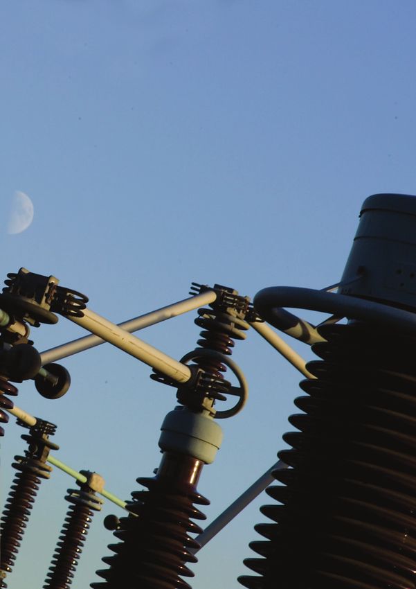
Snow-Flake Divertor:
A snow flake diverted configuration is characterized by a second order null, i.e. not
only the poloidal magnetic field vanishes (ordinary X-point) but also its first
derivatives and the separatrix divides the poloidal plane into six sectors (giving the
name to this configuration). The second-order null modifies the magnetic topology
near the plasma boundary by expanding the flux 2-3 times more than in the ordinary
X-point configuration. At the same time connection length in that region increases,
reducing the local heat load to the divertor plates in a similar way as described above.
15Fig.2.2: Different snowflake divertor configurations in the TCV tokamak.
Liquid metals
Liquid metal-based solutions (Li, Ga, Sn) could provide a heat load capability of up to
several tens of MW/m2. In addition, they relieve the problem of damage to the
surface. The problems here are twofold
• the compatibility with plasma operation due to the evaporation of the liquid
metal surface if the operating temperature is too high and the issues related to
MHD effects for plasma transients and/or for sufficiently high flow velocity.
• the fact that solution relying on evaporation probably cannot be used in a
continuously operating device.
The difficulty of handling liquid metal loops in a tokamak’s vacuum environment
means that any such system concept should be established as feasible with very high
priority.
Liquid metals
The use of liquid metals as plasma facing materials inherently bears the advantage
that they can act as plasma facing surface and as cooling medium simultaneously.
Additionally, there is no neutron induced damage as in solid materials. In order not to
dilute/contaminate the fusion plasma in a non-acceptable fashion, the sputtering yield
must be sufficiently low, as for a solid surface. However, impurity influx into the
main plasma induced by the generally higher vapour pressure compared to solids,
adds to the physical sputtering. It has to be kept as low as possible by controlling its
temperature. Depending on the technical solution, the cooling can be provided by the
flowing liquid and/or by secondary conventional cooling. MHD forces which are
induced by currents in the moving liquid itself or by plasma transients can distort the
liquid surface in such a way that it no longer can provide its protective function.
16Fig.2.3: Concept of capillary porous system (CPS) for a liquid lithium limiter in FTU.
(1 tubular element, 2 lithium filled CPS, 3 intermediate lithium volume, 4 coolant
inlet/outlet collector, 5 supporting elements, 6 channels for heat transfer)
2.3 Level of readiness now and after ITER.
Baseline strategy
Partial divertor detachment has been achieved but its behaviour cannot be described
by the existing numerical codes in a predictive fashion. Operation close to detachment
and close to the H-L threshold as foreseen in ITER requires still considerable efforts
investigating the confinement behaviour and control issues. Ultimately, ITER should
demonstrate by 2030 the applicability of its baseline strategy to the power loads
relevant for a reactor. In case of success, and with further development of divertor
modelling towards predictive capability, a full demonstration can then be made in
DEMO.
The technology solutions for the ITER divertor targets have been qualified in
accordance with the ITER divertor procurement strategy1 by using dedicated high-
heat-flux on test facilities (e.g., electron- and/or ion-beams) and will be demonstrated
in an operational environment on ITER. An early DEMO probably will use copper-
based water-cooled components (that will have to be tested on high heat flux test
facilities) while in parallel progressing with the R&D on W alloys (see Mission 3). If
the R&D on W-alloys is successful, elements could possibly be tested on DEMO.
Innovative geometries and liquid metals
Some innovative geometries and liquid metals have been tested so far in short pulse,
low power experiments and are at an early stage of development.
- The snowflake configuration has been produced in TCV and NSTX, showing
a reduction of the heat load on the divertor plate. However, a proper test would
require a modification of the divertor PFCs to have optimized divertor
17geometry. Also, to show that the snowflake divertor is compatible with the
particle control requirements, the divertor volume would have to be closed to
show the efficient buildup of neutral pressure compared to the main chamber
as well as the retention of eroded divertor armour material. The super-X
configuration is going to be tested in MAST starting in 2015.
- Liquid metals have been tested in CDX-U, LTX, NSTX, T-10, T-11, HT-7,
ISTTOK, FTU, TJ-II and EAST. These tests have mainly explored liquid
lithium in a broad range of solutions (fast/slow flows, static pools, jet injection
and capillary porous system). Experimental demonstrations of high power
handling have been done so far by evaporating the Li and a closed Li circuit
has not yet been demonstrated. These experiments have contributed to
developing the necessary know-how on the effects of liquid metals on plasma
conditions.
In order to assess the feasibility of both innovative geometries and liquid metals,
further tests at high heat loads, longer pulses are needed before testing them in a
device with higher plasma current (see below the gap analysis). In addition, the
technical feasibility and integration of these solutions under DEMO conditions must
be proven.
2.4 Main risks and risk mitigation strategies.
The main risks on the baseline strategy are:
- Too high H-L threshold power (Pthr);
- Power decay length (λq) smaller than expected;
- High radiation fraction not achievable without too high dilution/contamination
of plasma (Mission 1 risk)
- Lack of control of detachment.
If the stationary heat loads on ITER turn out to be too large, a possible solution would
be an increase of the DEMO dimensions above what is presently foreseen. However,
other limits (including cost constraints) may enter that prevent such a solution.
Risk mitigation strategies on detachment control and high radiative scenarios will
involve R&D activities on existing devices as well as progress in the understanding of
the L-H / H-L transition and detachment physics.
A detailed description of the risks is given in the risk register.
2.5 Options for Implementing the Work Packages and/or Gaps.
Most of the investigations in support of ITER and the baseline strategy of Mission 2
require operation in a diverted tokamak (see Table 1.1 in Mission 1 for main machine
parameters and capabilities of such tokamaks, in the EU and outside) with as close as
possible to the ITER/DEMO/FPP geometry and metal PFCs (C-Mod, AUG, JET,
ITER, WP 2.I.1-5, 2.III.1-3). Some more basic questions on the compatibility of H-
Mode operation with high radiative power exhaust or investigations on alternative
modes of operation (e.g. no/small ELM regimes) can be performed in a broader suite
of devices (Tokamaks: TCV, C-Mod, EAST, KSTAR, AUG, DIII-D, JET, JT-60SA,
18ITER; WP 2.I.4-5 and 2.III.2-3 – linear devices: MAGNUM, Pilot PSI, PISCES,
JULE PSI; WP 2.III.2-3). All of the above stated investigations have to be closely
accompanied by adequate modelling to assess their potential for extrapolation because
the baseline strategy can in principle only be fully implemented in ITER and its
success will not be demonstrated before the Q ~ 10 milestone is achieved. Thus, in the
absence of alternative solutions tested by 2030 at sufficiently large size and/or
implementable in ITER, a failure of the baseline strategy would lead to a delay in the
realization of fusion of ~20 years. For this reason, proof-of-principle experiments are
being performed in order to assess the capabilities of alternative divertor geometries
(Super-X: MAST-U, Snow-Flake: NSTX, TCV, WP 2.IV.1-2) and liquid metals
(LDX, FTU, NSTX, KTM, WP 2.IV.3). Given the early stage of development, it is
essential that these concepts will need not only to pass the proof-of-principle test but
also the assessment of their technical and integration feasibility on DEMO, perhaps
by adjusting the overall DEMO system design to the concept, before being explored
any further.
Nevertheless, the extrapolation from proof-of-principle devices to ITER/DEMO based
on divertor/edge modelling alone is considered too large. Thus, a vigorous
programme has to be put in place in the next few years to secure the achievement of
Mission 2. Depending on the details of the most promising chosen concept, a
dedicated test on JET/JT-60SA (if at all possible, but at reduced heat load) or on a
Divertor Tokamak Test (DTT) facility, entirely devoted to the divertor problem, will
be necessary.
The need of a DTT facility has been for some time advocated within the fusion
community [2.7]. The facility should be mainly aimed at the demonstration of
innovative geometries and liquid metals at a scale that can be extrapolated directly to
ITER and DEMO, but could also support the baseline strategy in case that it turns out
to be successful because of its envisaged capability to provide a large P/R. However,
the test of plasma facing components should be executed - whenever possible - on
beam facilities that avoid the complication of tokamak operation.
Technical requirements of a DTT could be depending on the assessment of the
different concepts:
- Large PSOL/R
- Potential for large transient thermal loads
- Flexible magnetic configuration to investigate different geometry of the
divertor
- Possibility of using liquid metals
- Actively cooled divertor components to allow a fast approach of equilibrium
conditions
Furthermore it could benefit from:
- High Twall for retention studies (see Mission 1)
- Large particle fluence to investigate evolution of armour under combined
power and particle load (see Mission 3)
The exact parameters of such a device cannot be fixed at this stage and are subject to
a proper review, which is part of the work packages.
19The evaluation of the scope and top-level requirements together with the definition of
the technical boundary conditions for such a facility should be completed by the end
of 2014. The analysis should consider the pros and cons of a single facility vs. a set of
parallel, more targeted, experiments. Such a facility could be either a new device or
an upgrade of an existing device, taking full advantage of the infrastructures already
available in various laboratories. The schedule should be realistic to fit with the start
of operation at the beginning of the next decade. In view of the large interest that this
line of research is getting in US, RF, Kazakhstan and China, opportunities for
international collaborations should be sought.
Materials and components tests should be preferably performed in dedicated test
devices. The requirements will be covered in Mission 3, which is also charged with
determining details of the necessary facilities. It is important to note that the testing of
the PFC and high heat flux materials will involve the testing of systems of materials
designed into engineering mock-ups, and hence the testing programme will have a
strong interaction with the development of divertor concepts.
2.6 Description of the major Work Packages.
The Work Packages can be divided into four groups. The first group aims at
demonstrating suitable schemes for controlled power exhaust in ITER and DEMO for
the baseline divertor strategy. In order to extrapolate the results of these
investigations, the second group of work packages concentrates on predictive tools for
divertor/SOL and PWI modelling. The third group deals with specific issues of the
erosion and damage of PFCs as dust production and melt layer behaviour. Finally the
last area of investigation is devoted to the investigation of alternative power exhaust
solutions for DEMO exploiting innovative divertor configurations and solutions with
liquid PFCs
References
[2.1] A. Loarte et al., Nucl. Fusion 47 (2007) S203
[2.2] R. Pitts et al., Phys. Scripta T138 (2009) 014001
[2.3] D.D. Ryutov, Phys. Plasmas 14 (2007) 064502
[2.4] F. Piras et al., Plasma Phys. Control. Fusion 51 (2009) 055009
[2.5] P.M. Valanju et al., Phys. Plasmas 16 (2009) 056110
[2.6] A.W. Morris, IEEE Trans. Plasma Science, 40 (2012) 682
[2.7] See e.g. R.J. Goldston Fusion Energy Conference 2010
20Annex 3. Mission 3 – Neutron Resistant Materials
Author: D Stork (CCFE)
Acknowledged contributions from the EFDA Materials Assessment Group members:
P Agostini (ENEA), J-L Boutard (ex-CEA), E Diegele (ex-Fusion for Energy),
D Buckthorpe (AMEC), S Dudarev (CCFE), C English (NNL), S Gonzalez (EFDA),
A Ibarra (CIEMAT), C Linsmeier (FzJulich), G Marbach (CEA), B Raj (India), M
Rieth (KIT), M-Q Tran (CRPP) and S Zinkle (ORNL)
Note: This Annex summarises the main findings of the EFDA Materials Assessment Group (MAG),
and independent group set up by the EFDA Power Plant Physics and Technology (PPP&T)
Implementing Agreement Board at the request of the CCE-Fu. The full report of the MAG was
delivered to the CCEFu and is given in document CCEFu57_7.1. The format of this Annex is, as a
result, somewhat different, but the Risk Logs and Development Programmes are fully equivalent to
those of the other Annexes, and are found in Annex 14 and 15..
3.1 Short description
The materials which require a degree of nuclear hardness for a Fusion Power Plant
can be divided into categories by the missions they themselves fulfil. These are:
- Structural Materials, which provide the structures (walls, base-plates etc) for
the in-vessel components, principally the Breeding Blanket (see Mission 4 and
also below), the Divertor cassette structure (see Mission 2) and the Vacuum
Vessel;
- Plasma Facing materials, which provide the ‘First Wall’ armour to take the
plasma impingement on the Breeding Blanket and the Divertor;
- High-heat flux materials, which allow efficient conduction of heat fluxes to
the in-vessel coolant channels, especially in the Divertor where the heat fluxes
in a reactor will be significant (several 10s of MW.m-2) [note that in the
Divertor region the armour has to have high-heat flux capability also];
- Functional materials, which are contained in the Breeding Blanket and take
on the roles (See Mission 4) of neutron-multiplication and tritium breeding.
The Assessment Group considered the Material Development for the first three
missions, as these are common to many Blanket and Divertor concepts. The
Functional Materials, whilst no-less important, are intimately embedded in Blanket
concepts and are therefore considered in Mission 4.
Material Damage in a Fusion Reactor
The internal components of a Fusion Reactor will be subjected to an intense
bombardment of high energy neutrons (up to loadings of 2MW.m-2) from the plasma
deuterium-tritium (D-T) fusion reaction. The neutron spectrum has a peak at the
energy released in the D-T reaction (14.1 MeV):
2
D + 3T 4He (3.5MeV) + 1n (14.1MeV)
Several critical phenomena are known to occur when neutrons are incident on
material surfaces. The knowledge of the severity of the interactions is established in
21irradiations with fission neutrons, where radiation “hardening”, radiation
embrittlement , radiation swelling and radiation-induced thermal creep and high
temperature helium embrittlement of grain boundaries have been measured [3.1].
These are primarily the result of displacements of atoms within the lattice following
inelastic neutron-atom collisions, with the resultant formation of self-interstitial atoms
and vacancies in the lattice that diffuse and aggregate to create a variety of extended
defect complexes.
Metals and alloys with a ‘body-centred-cubic (bcc)’ crystal lattice structure, including
iron and ferritic steels, and tungsten, show better resistance to prolonged irradiation,
in terms of much lower swelling and lower embrittlement, than metals with face-
centred-cubic (fcc) lattices. For example, the only class of steels that shows low
swelling in the high-dose ~ 200 dpa limit, at temperatures close to 420°C, are ferritic
(bcc) steels [3.2]. A comparison of the swelling under fission irradiation for ferritic
steels against austenitic (fcc) steels is shown in Figure 3.1,and this comparison is
usually taken as an unacceptable effect in terms of use of austenitic (eg. 316L
stainless) steels in a high radiation environment. The effect of neutron collisional
lattice damage is measured in ‘displacements per atom (dpa)’ and the onset of
radiation hardening and accompanying change in ductility is shown for a typical
ferritic-martensitic steel in Figures 3.2(a) and 3.2(b)[3.3]
Fig. 3.1: Comparative swelling after fission neutron irradiation for different steels.
300
250 Tirr =300-330°C
∆DBTT (°C)
200
150
100
50 KLST DBTT (FZK, NRG)
0 ISO-V DBTT (SCK)
0 10 20 30 40 50 60 70
Dose (dpa)
Fig. 3.2: (a)(left) Ductile-Brittle-Transition-Temperature (DBTT) change for Reduced Activation
Ferritic Martensitic steel (EUROFER) post- fission neutron irradiation at T ~ 300 -330°
(b)(right) Radiation hardening of EUROFER under fission irradiation at similar temperature.
[Data from reference [3.3]]
The irradiation damage which causes the embrittlement and hardening is known to be
‘annealed’ if irradiation occurs at higher temperatures (above 300-350°C). This is due
to the thermally-induced dissolution of small defect aggregates as the temperature
(and hence energy) is increased. Post-irradiation tests, summarized in figures 3.2, on
22steels after fission irradiation, show large hardening and an ~200°C increase in the
ductile to brittle transition temperature (DBTT) occurs for irradiation temperatures of
~ 300-350°C after ~20 dpa. This raises serious concerns about the viability of these
steels for fusion structures operating at or below 300-350°C without
mitigation measures, particularly since potential additional embrittlement from the
effects of neutrons with fusion-relevant energy levels, discussed in paragraphs below,
have not been included in the results.
Almost everything that is known about material degradation in intense neutron fluxes
comes from studies with fission (essentially moderate energy) neutrons. There are
however good reasons to suppose that the effects of the high-energy fusion neutrons
will be worse for a given neutron flux. One factor is that the inelastic lattice damage
collisions become at least an order of magnitude more probable at high neutron
energies (see Figure 3.3(a)). But the main factor is that primary knock-on atoms from
fusion neutron collisions have correspondingly more energy which directly leads to
more displacements. Moreover above a few MeV incident energy the neutrons
interact with the lattice atoms to produce transmutation products with accompanying
helium and hydrogen production (example in Figure 3.3(b)) in reactions of the type
A(n,α) B, and A(n, p)B. The helium atoms in particular are capable of coalescing into
microscopic helium bubbles which lead to further embrittlement of the material.
In addition to the neutron damage, the High heat flux and Plasma Facing metals
undergo bombardment by the ions and neutrals leaving the plasma. This is
particularly virulent at the divertor strike zones in a Tokamak, where the heat flux can
reach values over 20 MW.m-2 and the plasma particle flux can reach values over 1024
m2.s-1. In these cases there will be a high level of sputtering and erosion of the
material surface. Robustness against this damage (which will eventually erode the
surface of the divertor and necessitate a replacement) is the key parameter in the
selection of divertor materials and is discussed below.
Fig. 3.3(a)(left) Relative variation of neutron cross sections with iron as a function of energy. The blue
curve gives the inelastic displacement damage cross section.
(b)(right) Example of a threshold transmutation reaction (hydrogen production in Chromium)
involving high energy (MeV level) neutrons
The objectives of Mission 3 may be stated as:
- To develop full scientific and engineering characterisation, and theoretical
understanding of:
o Neutron resistant structural materials able to withstand high levels
of 14MeV neutron flux and maintain their structural and thermo-
23mechanical properties, including in a welded condition, in a
sufficiently wide window of operation and for a sufficiently long
lifetime exposure (fluence) for DEMO reactor and Fusion Power Plant;
o High heat flux and Plasma Facing Materials able to withstand the
combined effects of 14 MeV neutron flux and high intensity plasma
ion/neutral bombardment and maintain their mechanical and thermo-
mechanical properties and erosion resistance in a sufficiently wide
window of operation and for a sufficiently high combined fluence for
DEMO reactor and Fusion Power Plants;
- To produce and qualify suitable structural and high-heat flux materials that
also exhibit reduced activation so as to avoid permanent waste repositories;
- To develop industrial production and fabrication methods for the Structural
and High heat flux and Plasma facing materials, which could lead to cost
savings;
- To aim, in the long run, for materials capable of extra high temperature to help
achieve high thermodynamic efficiency for a Fusion Power Plant, and if
possible for a DEMO machine.
3.2 Critical aspects for reactor application.
3.2.1 Operating Ranges and engineering robustness of Materials
The internal components of a fusion reactor will experience a variety of operating
conditions: temperature, temperature gradients, the local radiation dose, dose rate, and
neutron energy spectrum. These parameters will have a significant impact on the
materials selections and development. To define the materials requirements a systems
engineering approach must be adopted viewing each of the major sub-assemblies
which require structural, HHF and PF materials as engineering materials systems.
Temperature distributions in the divertor and breeding blankets are going to be highly
non-uniform, thus each component of these structures, must have its temperature
lying within the boundaries of the temperature operating window for a given material,
defined by the requirement that the material retains its structural integrity under
neutron irradiation.
A temperature operating window for a material is normally defined in terms of its
steady-state response to irradiation, or more generally in terms of stability of its
microstructure over the timescale of operation of the material in an engineering
application. 1
Important considerations in identifying and characterising the temperature operating
window are:
- The identification of a time interval over which a material can operate outside
its conservatively-defined temperature operating window, which has
implications for the reactor design and modes of operation;
- The compatibility of (interaction between) the different materials used in a
structure, as an essential requirement associated with the selection of
candidate materials;
1
In reality for a specific concept the situation is more complex and stress (primary and secondary) and strain, their
cyclic ranges, number of cycles all define a highly complex multi-dimensional design space. Thus to take zero
approximation, simply defined by upper and lower temperatures, has to be done with a safety margin at each end
of the 'window'.
24You can also read