Packaging - Blower & Vacuum Best ...
←
→
Page content transcription
If your browser does not render page correctly, please read the page content below

The Magazine for ENERGY EFFICIENCY in Blower and Vacuum Systems

                                                                                           August 2021
                                                             INDUSTRIAL BLOWER
                                                             & VACUUM SYSTEMS

                                                               6
                                                                 Paper Machine Vacuum

Packaging                                                        Systems: Liquid Rings
                                                                 vs. Blowers

                                                              10
                                                                 Case Studies in Dry vs.
                                                                 Wet Vacuum Pumps

                                                              26
                                                                 Tea Packaging Quality
                                                                 Improved with Vacuum
                                                                 Conveying Upgrades

AERATION BLOWER SYSTEMS

18		Aeration Blower Control
     Strategies
Dare to Compare.

                           The isentropic efficiency for variable speed screw and
                           turbo blowers is 20-35% better than multi-stage blowers

Picking the Right Blower Technology
Blowers are critical assets for wastewater treatment plants, and they
are often the biggest energy consumers in the plant. Choosing the
best blower is vital for plant operational success; however, too often
engineers and operators, stick to blower technology they know best,
rather than taking the time to compare blower technologies.

Multistage blowers have been a popular choice for many years, but
did you know rotary screw and turbo blowers have better isentropic                                                                Solving your system
efficiencies than multistage blowers?
                                                                                                                                      challenges.
If it’s time to replace aging multistage blowers, don’t miss the
chance to consider alternatives that may cut your energy bill and
improve the effectiveness of your treatment plant.

Take the dare and compare. Visit us.kaeser.com/bvbp to learn
more.

                         Kaeser Compressors, Inc. • (866) 516-6888 • us.kaeser.com/bvbp
                    The Kaeser logo is a registered trademark of Kaeser Kompressoren ©2021 Kaeser Compressors, Inc. All rights reserved. customer.us@kaeser.com
A U G U S T    2 0 2 1   |   V O L U M E   7 ,   N O .      3
                                                                                                              |

INDUSTRIAL BLOWER & VACUUM SYSTEMS
 6    Paper Machine Vacuum Systems:
      Liquid Rings vs. Blowers
      By Andrew Smitneek, Growth Solutions Consultants

10    Case Studies in Dry vs. Wet Vacuum Pumps
      By Tie Duan, E.W. Klein & Co.

26    Tea Packaging Quality Improved with Vacuum
      Conveying System Upgrades
      By Nora Ashmen, VAC-U-MAX

                                                                                                                   6

                                           AERATION BLOWER SYSTEMS
                                            18   Aeration Blower Control Strategies
                                                 By Tom Jenkins, JenTech Inc.

 10

EVERY ISSUE
 4    From the Editor
30    Industry & Technology News
34    Advertiser Index
34    The Marketplace | Jobs and Technology                                                                       18

                                                                                                       blowervacuumbestpractices.com   3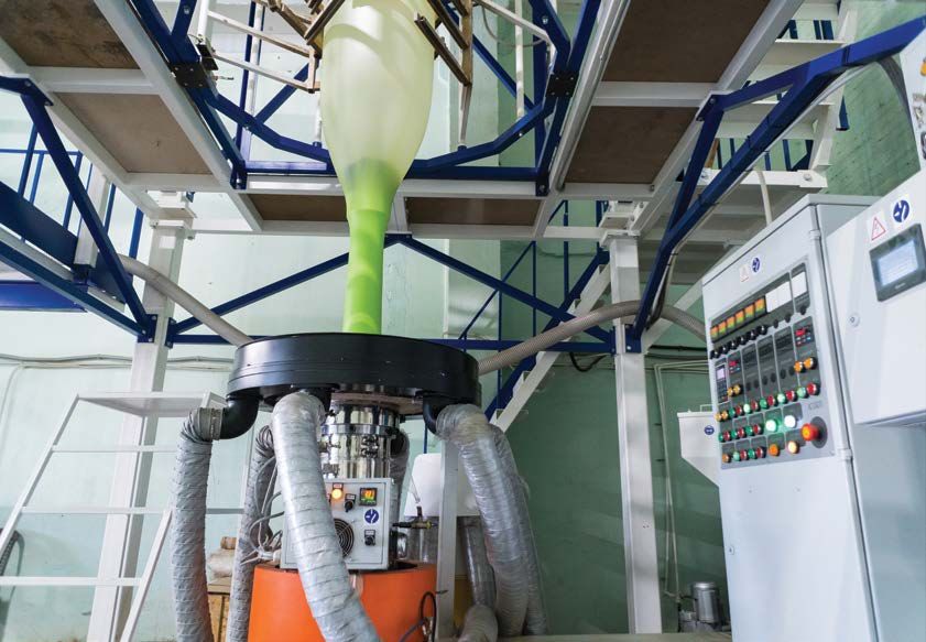
| 0 8 / 2 1
FROM THE EDITOR
Industrial Blower & Vacuum Systems BLOWER & VACUUM BEST PRACTICES
EDITORIAL ADVISORY BOARD
Modern paper machines carefully remove water from the paper
Danone North
sheet by using vacuum created by either liquid ring vacuum pumps Doug Barndt Energy Manager
America
or turbo blowers. Andrew Smitneek has a long career’s worth of Facilities Gentex
John Bilsky
knowledge (his biography says he’s retired four times!) on this topic. Maintenance Corporation
I hope you enjoy his article reviewing the pros and cons of using Corporate Energy
Bhaskar Dusi CEMEX USA
Manager
these technologies.
Senior Energy
Richard Feustel Leidos
Advisor
Tie Duan, from E.W. Klein & Co., has sent us his third excellent vacuum fundamentals article
William Jerald Energy Manager CalPortland
Industrial Energy Managers
this year. This one is titled, “Case Studies in Dry vs. Wet Vacuum Pumps.” It’s a useful piece
Director Corporate Intertape
for every plant and every vacuum sales engineer trying to optimize vacuum systems. Michael Jones
Energy Polymer Group
GTS Energy Stanley Black
Vacuum conveying has long been used in the food industry. Automating the movement of food, Robert Kirts
Manager & Decker
in the plant, can never come at the expense of food quality. Nora Ashmen, from VAC-U-MAX, Energy/Reliability
Kurt Kniss Shaw Industries
has sent us an interesting case study about how a tea manufacturer resolved a quality control Engineer
issue related to their vacuum conveying system. Corporate Energy
Leslie Marshall General Mills
Engineer
Group Energy Klöckner
Aeration Blower Systems Ethan O’Brien
Manager Pentaplast
“Aeration Blower Control Strategies” is the title of our latest article from Tom Jenkins, Senior Utilities Nissan North
Brett Rasmussen
Engineer America
from JenTech Inc. If you “get technical” with positive displacement and centrifugal
Director Energy Purdue
(turbo) blowers, the calculations and graphs will challenge you! You can also hear Brad Runda
& Utilities University
Mr. Jenkins make a presentation on this topic by visiting our Webinar Archive pages
Principal-Industrial
Woodard &
at https://www.blowervacuumbestpractices.com/magazine/webinars Bert Wesley, Sr. Plant Engineering
Blower & Vacuum Assessments
Curran
Practice Leader
Thank you for investing your time and efforts Stephen Horne
Blower Product
Kaeser
Manager
into Blower & Vacuum Best Practices.
Harris
Phil Kruger General Manager
Equipment
ROD SMITH, Editor
Ralph Wilton Marketing Manager Aerzen
tel: 412-980-9901 Register at https://cabpexpo.com
rod@airbestpractices.com
SFI-00993
2021 MEDIA PARTNERS
4 blowervacuumbestpractices.com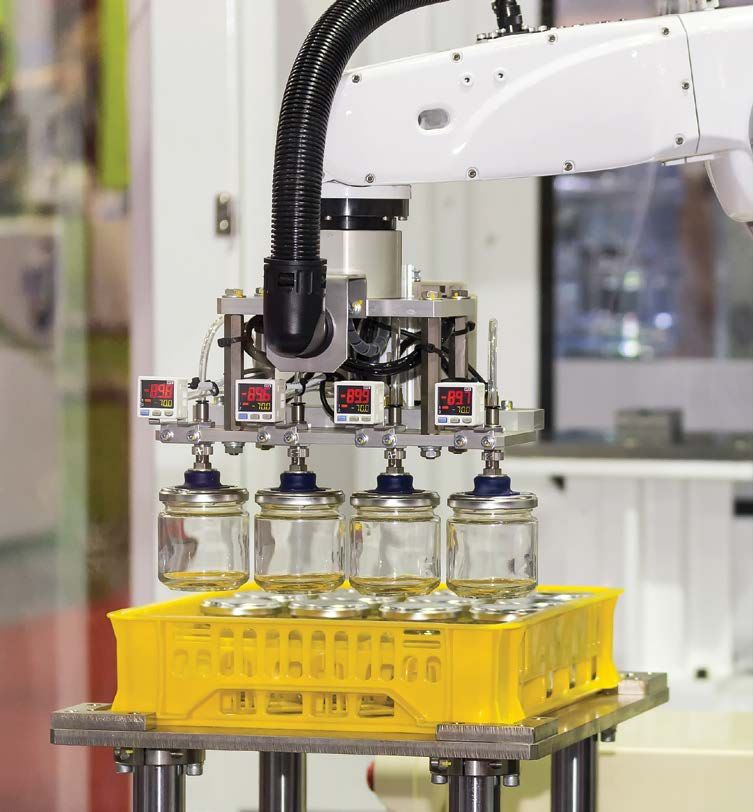
Jan. 25 – 27, 2022
                                 Atlanta, GA USA

                                      {
                                                      SERVICES
                                                      BUYERS
RECONNECTING                                          NETWORKING
    YOU WITH                                          TRENDS
   THE ENTIRE                                         INNOVATION
    INDUSTRY                                          NEW PRODUCTS
                                                      SOLUTIONS
                                                      TECHNOLOGY
                                                      AND MORE

Join us for the in-person 2022 IPPE where you can evaluate products, new technology
     and services that meet your needs while reconnecting with your colleagues.
                       Register at www.ippexpo.org #IPPE
|   0 8 / 2 1                                                                  INDUSTRIAL BLOWER & VACUUM SYSTEMS

                                    Paper Machine Vacuum Systems
                                       Liquid Rings vs. Blowers
                                                By Andrew Smitneek, Growth Solutions Consultants

    c Introduction                                      p   If you want to run without measuring       variable speed to meet the curve shown in
    So you need a vacuum system for your paper              or controlling anything, you want          Figure 1.
    making machine. Take a deep breath and read             a liquid ring pump.
    on. Blowers versus liquid ring vacuum pumps,                                                       Blowers vs. Liquid Ring Vacuum
    the short list:                                     p   If you want to save energy, you will       Pumps – How they Work
                                                            want a turbo blower.                       Any air pressure, lower than local
    p    If you need less than 3" Hg vacuum                                                            atmospheric, is called a vacuum. This is the
         (90 kPa) you want a fan.                       p   If you want to use a blower, you will      definition. A machine that can remove air
                                                            have to measure, understand and            from a chamber, faster than it can leak in,
    p    If you need more than 18" Hg                       control the blower speed to the process    is called a vacuum pump. The vacuum pump
         (40kPa) you will need a liquid                     parameters.                                gathers air at a low pressure and discharges
         ring vacuum pump.                                                                             it to a higher pressure (the atmosphere).
                                                       The approximate energy comparison of the        It is by definition a compressor.
    p    If you want a machine that will               best turbo blower versus the best very large
         run for a very long time with little          liquid ring pump is on this chart; note that    A paper machine carefully removes water from
         or no attention, you will want                the liquid ring pump is running at a constant   the paper sheet. Some of this water removal
         a liquid ring pump.                           speed, the turbo blower would have to be        is done by passing air through the sheet, thus

6   blowervacuumbestpractices.com
INDUSTRIAL BLOWER & VACUUM SYSTEMS                                                                             0 8 / 2 1
                                                                                                                            |

moving the water from the sheet to the wire.
Air is moved by creating a pressure differential
across the sheet. This is normally done by
putting the sheet on a wire and then putting
a box under the wire and then evacuating the
air from the box. The resistance of the air
movement through the sheet and wire causes
the pressure drop from the machine room to
the box.

Two different devices are commonly used
to create a vacuum, the liquid ring pump and
the turbo blower. Within practical bounds
of operation, they work as follows:

The liquid ring pump is a positive displacement
isothermal compressor. In thermo dynamic
terms, isothermal compression is the most           Figure 1.
efficient. It is also a constant volume device if
it is run at a constant speed. Unfortunately, the
liquid ring pump uses water as the piston, and
moving the water in the largest most efficient           Need a vacuum
liquid ring pumps consumes one third of the
power put into the pump. In smaller, more                pump fast?
commonly used pumps, this number is closer
to half of the power.
                                                         Exchange PLUS
                                                                                                 NEW MODULE
The turbo blower is a constant pressure                                                          ON EVERY R5
adiabatic compressor. In thermodynamic                                                          VACUUM PUMP
terms it is less efficient than the isothermal
compressor. However, the enormous energy
drain of moving the water in the liquid ring
pump makes the turbo compressor more
efficient. Also, because the compression
is adiabatic (without exchange of heat),
the air coming out of the blower is typically
392°F (200°C), there is energy there that
can be reclaimed.                                        Quick change-over in breakdown situations.
                                                          • 100% remanufactured
                                                          • 24 month warranty
In a liquid ring system, the vacuum in the                • 24 hour response
box is created by the resistance to the air               • Pick-up and delivery
                                                         Exchange PLUS is fast, simple, cost-effective.
flow through the sheet and carrier because
                                                         1-800-USA-PUMP │ info@buschusa.com │ buschusa.com
the pump is constant volume. As a felt fills
and compacts the resistance to flow increases

                                                                                                                     blowervacuumbestpractices.com   7
|   0 8 / 2 1                                                                       INDUSTRIAL BLOWER & VACUUM SYSTEMS

        FREE                                         Paper Machine Vacuum Systems: Liquid Rings vs. Blowers

        SUBSCRIPTION
        D I GI TAL E DI T I ON FREE WORL D WID E
        PRINT EDITION FREE TO U.S. SUBSCRIBERS

                                                     Two of twelve medium-sized liquid ring vacuum pumps on a fine paper machine.

                                                     and the air velocity through the felt increases          cannot tolerate any contamination. Failure of
                                                     thus increasing the velocity of the air through          a liquid ring pump is usually very slow and
                                                     the felt. This is an automatic compensation              predictable. Failure of a turbo blower is usually
                                                     for felt filling as the increased air velocity will      rapid and catastrophic.
                                                     increase the water removal.
       EVERY ISSUE CONTAINS                                                                                   Paper Machine Vacuum System
       BEST PRACTICES FOR                            In a turbo blower system the pressure in the             Surveys
                                                     box is created by the blower, and the air flow           Measurement of the water removed and
       Industrial Vacuum                             is dictated by this pressure. As the felt fills          careful experimentation with your product
                                                     the resistance to air flow increase however              versus water removal is a very good idea, as
       Vacuum Generation                             the pressure remains constant and the air                it will remove variability from your process
                                                     flow decreases. The power used by the blower             (remember 6 sigma?). Either the turbo blower
       Industrial & Aeration                         also decreases as it is dependent upon the air           or the liquid ring pump can and should
       Blowers                                       flow. In modern systems, the water removal
                                                     by the vacuum system is measured and the
                                                                                                              be speed controlled for optimum energy
                                                                                                              performance.
                                    Subscribe Now!

       Blow-Off Air                                  blower speed increased to optimize the water
                                                     removal. In this sense it mimics the liquid              Most paper machine have too many vacuum
                                                     ring without controls.                                   pumps and also have uncontrolled vacuum
                                                                                                              systems. The very large energy gains reported
                                                     The liquid ring pump is robust, runs slowly              by going from a liquid ring system to a
                                                     and can handle an enormous amount of excess              turbo blower system are partially caused
                      Subscribe at                   water and junk running through it. The turbo             by elimination of vacuum capacity from
     blowervacuumbestpractices.com                   blower is finicky to control, runs very fast and         the system. In many cases this vacuum

8   blowervacuumbestpractices.com
INDUSTRIAL BLOWER & VACUUM SYSTEMS                                                                                       0 8 / 2 1
                                                                                                                                       |

elimination can be done without replacing the     savings of 1000 kW over the original design.          could breathe 250 times per minute you would
pumps. A vacuum survey, experimentation,          Without the experimentation, measurement              move about 1800 m³/hr. This is what a liquid
performance measurement and controlling           and controls this would not have happened.            ring pump with your lung capacity would do.
the speeds of the liquid ring pumps will often                                                          Call me for the calculation.
get good enough results to avoid the higher       The design of the vacuum system and the
capital of a complete system rebuild.             troubleshooting of an existing system is              About the Author
                                                  complicated but not impossible. Before you            Andy Smiltneek is an independent consultant
For a new paper machine, a hybrid system          undertake this activity, you should study and         and president of Growth Solutions Consultants
with fans, blowers and liquid ring pumps is       consult with independent people who have              LLC in the U.S.. Andy has lived and worked
desirable.                                        done this before.                                     in the U.S. and China and has retired 4 times.
                                                                                                        He will consult anywhere in the world.
The vacuum system must be measured and            So take a deep breath and understand that             Visit www.growthsolutionconsultants.com
controlled. I worked on one such system in        your lungs work like a liquid ring pump. If you
Europe where after the machine was built with
4 liquid ring pumps with 3000 kW connected
and after two years two of the pumps were shut                         To read similar Vacuum System Assessment articles visit
                                                           https://www.blowervacuumbestpractices.com/system-assessments/vacuum-systems
down wit the other two running faster, for a

   Setting the standard
   since 1854
   Howden manufactures the world-renowned Roots™ rotary positive
   displacement blowers and centrifugal compressors in Connersville, IN
   and Springfield, MO.
   Designed and fabricated to unique applications within a wide array of
   industries including pneumatic conveying, gas separation, wastewater treatment,
   steam compression, and petrochemical production. Maintain optimized production
   levels with Howden factory maintenance and repair services available worldwide.

     Universal RAI              RGS-J Gas Compressor              Centrifugal Compressor                TRI-NADO™                    EasyAir™ Rotary
     Bi-lobe Blower                                                                                 Tri-lobe Exhauster           Factory Blower packages

   For more information contact:
   Tel: 1 800 55 ROOTS (76687) | Email: inquiries.USA@howden.com

                                                                                                                                blowervacuumbestpractices.com   9
|   0 8 / 2 1                                                                               INDUSTRIAL BLOWER & VACUUM SYSTEMS

                                                  Case Studies in Dry vs.
                                                   Wet Vacuum Pumps
                                                             By Tie Duan, E.W. Klein & Co.

     c Why is my vacuum pump failing? Do I
     continue replacing/repairing my pumps or try
     a new vacuum technology? What is the learning
     curve for a new pump technology? How will a
     change in vacuum pump affect my plant utilities?

     Many of our customers have grappled with
     these questions. In our recent travels, we
     have seen more and more exploration and
     experimentation with different vacuum
     technologies on existing processes. Liquid
     ring vacuum pumps being replaced by claw
     pumps, rotary vane pumps being replaced by
     liquid ring vacuum pumps, claw pumps being
     replaced by screw pumps, etc. Although the
     results have yielded many success stories and
     some unexpected challenges, we still believe
     these trials are not only healthy challenges
                                                        Typical vacuum applications in plastics extrusion process.

10   blowervacuumbestpractices.com
INDUSTRIAL BLOWER & VACUUM SYSTEMS 0 8 / 2 1
|
to status quo, but also necessary to push the Extrusion Degassing
boundaries of vacuum applications, and drive In plastic extrusion processes, moisture and
innovations in different industries. volatile gas are often removed from the molten
plastic by vacuum pumps. Insufficient off-gas
Typically, when our engineers evaluate the removal can result in visual defects or poor
suitable vacuum technology for an application, physical properties in the final products.
we take these areas into consideration:
The set-up: Company A has a twin-screw
p Process vacuum level extruder running XYZ polymer with various
powder additives. A claw vacuum pump is used
p Capacity demand for extruder barrel degassing.
p Process carry-over’s interaction The problem: Not enough moisture and
with pump’s internal seal liquid, volatile gas is pulled out of the extrusion
coating, metal, seals, etc. process causing product defects. The claw
pump requires constant rebuild as powder
p Discharge gas/vapor/liquid/particle additives pulled out of the extruder get into
disposal regulation the claw pump.
Cutaway view of inlet vapor condenser.
p Environmental constraints Our approach: Proper extruder barrel venting
(floor drain location, heat can be critical to the final product’s physical
dissipation, noise level, etc.) and visual quality. Generally, the deeper the
vacuum, the better the degassing. A single-
p Utility availability stage claw pump’s ultimate vacuum level is
limited to 25 in-Hg gauge. For some extrusion
p Cost of ownership applications, effectively removing all volatile
gas from raw materials with high moisture
p Motor efficiency content (e.g., un-dried regrind) requires
a vacuum technology with deeper ultimate
As one can see, these above dynamic vacuum level than 25 in-Hg.
parameters go beyond just a vacuum
technology’s vacuum level and CFM capacity. When dealing with process carry-overs in
To summarize this decision-making process a vacuum application, the basic philosophy
into a simplified one-size-fits-all flow chart we follow is to either prevent it from getting
would effectively force any complex real- into the pump or let it pass through without
world scenario into a sterilized thought damaging the pump. In general, the claw
exercise. Instead, we present a few case pump is easy to install and operate. However,
studies derived on real-world application any process carry-over must be addressed.
examples, where various vacuum technologies If not filtered or separated prior to entering
may be suitable solutions. These examples the pump, the claw pump’s internals can see
do not contain company names or extensive severe abrasion, corrosion, and clogging.
process details, so to protect proprietary The gas and vapor pulled out of the extrusion
information. Each case is generalized enough process can become a very complex chemical
that the knowledge is applicable across mixture, presenting significant challenges to
multiple specific applications. claw pump’s reliable performance. This is Add-on auto-drain kit to the vapor condenser.
blowervacuumbestpractices.com 11| 0 8 / 2 1 INDUSTRIAL BLOWER & VACUUM SYSTEMS
Case Studies in Dry vs. Wet Vacuum Pumps
especially true as the production raw material
E.W. Klein & Co. Celebrates 100 Year Anniversary recipe changes (e.g. adding talc powder,
Only a handful of companies last 100 years, and E.W. Klein is beginning the celebration of calcium carbonate powder, liquid colorant, UV
its 100th anniversary thanks to you and the great companies we represent, such as Gardner stabilizer, fire retardants, recycled flakes, etc.).
Denver, Alfa-Laval heat exchangers and other equipment. Founded in 1921, E.W. Klein & Co.
is a leading manufacturer’s representative of engineered vacuum and heat transfer equipment Our solution: For this application, we
to the chemical, paper, power, and general industrial markets. converted it to a liquid ring vacuum pump in
recirculation setup, which can reach deeper
Our Roots: Based in Atlanta, E.W. Klein was selected as Nash Engineering Co’s first vacuum level of 28 in-Hg. We decided to put
representative in 1921. Nash’s original focus was on steam heating systems common in in an inlet vapor condenser separator between
buildings of that time. Later, Nash developed their world-famous line of Nash Hytor vacuum the extruder vent port and vacuum pump
pumps. Still a leader in vacuum today, Nash is now part of the Gardner Denver product inlet. This device uses chilled water/cooling
line recently merged with Ingersoll-Rand. tower water to condense the incoming gas and
vapor then collect the condensable for manual
2020 was a challenging year for us all. Since the founding of the company back in 1921, E.W. discharge and cleaning. The vapor condenser
Klein & Co has come through all kinds of difficulties: wars, depression, recessions, natural prevented majority of the volatile gas and
disasters, stock market crashes, a pandemic, and everything in between. Through it all, it vapor from reaching the liquid ring vacuum
has been the people of E.W. Klein – our employees, great customers, and the equipment we pump. A secondary knock-out pot was placed
represent – who have made the difference. COVID has taught us that we can make it through between the vapor condenser and the pump
the tough times and make sure we celebrate the good ones too, now and for the next 100 inlet to drop out any liquid and particles. The
years. Looking forward to 2021 and past COVID: A part of our overall growth plan was moving residual amount of carry-over that makes it
to a new location that has allowed us to stock and repair pumps and other equipment that we into the liquid ring vacuum pumps can easily
represent. We are excited about our new capabilities that will allow us to service the customer be handled by the pump. As a result, the
better than ever. high cost of frequent claw pump rebuild is
eliminated by periodic flushing of the liquid
The keys to our success have always been our dedicated technical-focused staff, developing ring vacuum pump recirculation system.
strong relationships with our diverse customer base, and capitalizing on new opportunities.
For more information about E.W. Klein and the great companies we represent, please visit The X-factor: This vapor condenser was
www.ewklein.com. so effective it requires constant manual
discharging and cleaning. To reduce the
dependency on manual intervention, an auto-
drain system was put in to discharge the
condensed liquid based on level sensors
inside a drain pot at the bottom of the unit.
Because the recirculation system requires
chilled water to cool down seal water, the
customer was concerned with their chiller
capacity as this solution is expanded to
additional extrusion lines. Unlike a claw
pump where heat generated from internal
compression is dissipated into the surrounding
atmosphere, a liquid ring vacuum pump’s heat
is almost completely removed by the seal water.
In a recirculating seal water loop, the heat
12 blowervacuumbestpractices.comINDUSTRIAL BLOWER & VACUUM SYSTEMS 0 8 / 2 1
|
removed from the pump by seal water equals resulting in poor hold down performance and
to the heat chilled water picks up through the frequent pump failure.
heat exchanger. That heat transfer rate can be
converted from the pump’s brake horsepower Our approach: For cutting substrate that
using below equation. are porous, like the MDF panels, a vacuum
pump needs be to able to pull to the desired
Heat Transferred (Btu/hr) = Pump Brake vacuum level to prevent the panel from
Horsepower (bhp) × 2,544.43 Btu/hr moving while being cut. It also needs to
have enough CFM capacity to handle the air
being pulled through the panel without losing
CNC Vacuum Hold Down vacuum depth. While the existing liquid ring
Various vacuum technologies are being used vacuum pump system has inlet filter, it is
to hold down the product while a CNC router easily clogged by the large amount of routing Regenerative Blower, also called Side Channel Blower.
cuts it into shape. Many of these are selected dust produced from this process. Once the
by the OEMs of the CNC machines, which are dust gets into the pump system, it tends For this application, the vacuum depth needed
often designed to cut a limited selection of to stay in the recirculation loop, causing was only 10 in-Hg gauge, so we decided to
materials. However, once these machines get abrasive wear on internal components and replace the liquid ring vacuum pump system
into the real-world applications or the lively reduce heat transfer efficiency of the onboard with a regenerative blower, which can reach
used equipment market, all kinds of materials air-water cooler. this vacuum level and provide high air flow
can be cut on these machines. In many cases,
the OEM supplied vacuum system might not
be the best fit for these non-ideal application
conditions.
The set-up: A liquid ring vacuum pump in
an air-cooled self-contained recirculation
package is used to perform hold down ANEST IWATA oil-free scroll
on CNC machines that cuts wood panels. vacuum pumps are compact
The problem: Fine dust gets into the and quiet. We offer a variety
recirculation system and causes clogging of of pumps in the range
the seal water lines, overheating the pump,
of 2 CFM to 42 CFM with
ultimate pressures down to
1 Pascal that can suit your
budget and needs.
www.anestiwata.com
vacuuminquiry@anestiwata.com
Toll free: 800-440-0282
Gardner Denver Elmo Rietschle 2BL Air-Cooled Self-
Contained “Pump-In-A-Box”.
blowervacuumbestpractices.com 13| 0 8 / 2 1 INDUSTRIAL BLOWER & VACUUM SYSTEMS
FREE Case Studies in Dry vs. Wet Vacuum Pumps
SUBSCRIPTION capacity. A larger inlet filter with finer filter some challenges to short-staffed maintenance
element was also installed, to improve process teams and housekeeping.
D I GI TAL E DI T I ON FREE WORL D WID E carry-over prevention. Due to the internal
PRINT EDITION FREE TO U.S. SUBSCRIBERS design of a regen blower, it can tolerate some The set-up: A customer uses a dozen robotic
fine dust being pulled into it. This regenerative pick-and-place machines with oil-lubricated
blower was installed outdoors adjacent to the rotary vane vacuum pumps to package a
wall where the CNC machine is installed inside. certain product. This is a 24/7 operation with
This helped to keep the noise level at the little appetite for equipment downtime, planned
production area low and allowed occasional or unplanned.
exhaust of routing dust outdoors for easier
housekeeping in the shop. The problem: The rotary vane pumps emit
fine oil mist from their discharge, resulting
The X-factor: Some routing applications in housingkeeping issues. The customer tried
required higher vacuum level, such as water putting in inlet filters, discharge oil demisters,
jet cutting of granite countertops. To ensure and implementing rigorous separator filter
the heavy granite does not move while being change and oil change schedule. While these
cut and be able to handle the water introduced measures reduced the oil misting, they did not
to the vacuum system, a water-sealed liquid eliminate it, especially with a dozen machines
ring vacuum system or a claw vacuum pump in close proximity inside a poorly ventilated
with extensive inlet liquid separation can be warehouse. As a result, these measures
retrofitted to the cutting machine. increased the cost of ownership without
completely solving the housekeeping problem.
Pick-and-Place
Pick-and-place operations typically see oil- Our approach: To address the pain points
lubricated rotary vane pumps as the main of cost of ownership and housekeeping, we
source of vacuum, but the frequent maintenance turned to a different version of dry vacuum
and oil misting from these pumps can present pump. While oil-less rotary vane pump and
EVERY ISSUE CONTAINS
BEST PRACTICES FOR
Industrial Vacuum
Vacuum Generation
Industrial & Aeration
Blowers
Subscribe Now!
Blow-Off Air
Subscribe at
blowervacuumbestpractices.com
Operating principal of a scroll pump.
14 blowervacuumbestpractices.comINDUSTRIAL BLOWER & VACUUM SYSTEMS 0 8 / 2 1
|
claw vacuum pump can both perform this Instead, we trialed a new air-cooled, oil-free installations in these dirtier applications,
pick-and-place function, oil-less rotary vane vacuum technology: scroll pump. This type of claw pump with proper inlet filtration would
pump has internal vane wear which results vacuum pump utilizes the scroll mechanism for be another suitable solution, especially in
in frequent maintenance downtime. The claw continuous process suction, compression, and facilities with no process cooling capability.
pump has higher initial capital investment and exhaust with little change in torque. This pump
its larger footprint makes it difficult for drop-in eliminates the need for oil, has much longer Pharmaceutical Distillation
replacement. Small vacuum generators were service intervals than rotary vane pumps, has In vacuum distillation, a liquid or solution is
also evaluated but eliminated due to this facility’s lower initial cost, and is compact in size for removed from a mixture when the surrounding
hyper-awareness of their compressed air usage. easy drop-in replacement. Below is a basic atmospheric pressure is reduced to below
operating principal diagram. this liquid or solution’s vapor pressure, so
it boils off without excessive heat is applied.
The X-factor: The scroll pumps are suited In pharmaceutical industries, this technique
for relatively clean vacuum applications. In is often used to remove isopropyl alcohol or
other pick-and-place applications where dust other type of solvent from the product mixture.
is easily introduced into the vacuum pump
(e.g. Cardboard packaging), centralized The set-up: A customer retrofitted claw vacuum
liquid ring vacuum pumps are the more pumps on a pharmaceutical distillation process
preferred vacuum solution. For decentralized to remove solvents from their product mixture.
ANEST IWATA Scroll Pump DVSL-500E.
Presenting the 2021
Engineering Firm Webinar Series
Learn from Experts at Black & Veatch, Woodard & Curran and Jacobs with
FREE Live and On-Demand Webinars
*
Upcoming LIVE Engineering Firm Webinars Library of Engineering Firm Webinars Includes
p November 18: Precise Cooling Temperature Control Ensures p Managing Cooling Tower Cycles of Concentration
Quality and Increased Cycle Counts – Bert J. Wesley, P.E., Sr. – Nick McCall, P.E., Technical Manager, Woodard & Curran
Principal, Industrial Plant Engineering Practice Leader, Woodard & Curran p Sorting Through the Menu of Aeration Blower
p December 6: Measuring KPI’s for Efficiency: kW, Flow Technologies – Julie Gass, P. E., Lead Mechanical Process
and Pressure – Tim Dugan, P.E., President and Principal Engineer, Engineer, Black & Veatch
Compression Engineering Corporation *Included with your free magazine subscription
Get FREE Instant Access* to Webinars ��� https://airbestpractices.com/magazine/webinars
blowervacuumbestpractices.com 15| 0 8 / 2 1 INDUSTRIAL BLOWER & VACUUM SYSTEMS
Case Studies in Dry vs. Wet Vacuum Pumps
The problem: The claw pumps failed within weeks of operation. 3. Process vapor will damage the internals of an air-cooled self-
Upon inspection, the point of failure was isolated to internal seals. contained recirculation system.
The seals were found to be incompatible with the solvent vapor
pulled into the pump. 4. Process vapor condensed in the seal water will also change seal
liquid vapor pressure, reducing pump performance.
Our approach: Liquid ring vacuum pumps are
often used for vacuum distillation process. This limited our solution to either heavily
However, it is limited in this application due to: modifying the claw pump with custom
chemically resistant lip seal and compatible
1. Pump discharge water is contaminated shaft sleeve or installing screw vacuum pump.
with harmful process vapor and residual Screw vacuum pumps are typically designed for
product powder, requires investment processes that see vapor carry-over and most
in water treatment facility. of the times it requires a customized solution
to match the challenges. It takes the approach
2. There is no chiller or cooling tower of “letting it pass through without damaging the
onsite, preventing the implementation pump”. Screw pumps often require a period of
of a recirculation system. warming up before it is opened to the process.
This is to ensure the screws’ geometric grows
Gardner Denver Nash NDC Claw Vacuum Pump.
OPTIMIZE
ON-SITE UTILITIES
Powering Automation
Assure Product Quality & Safety
What can you do to reduce product rejects, mitigate the
risk of contamination, minimize downtime, and decrease
maintenance expenses? Attend Best Practices EXPO
& Conference and learn how to prevent impurities from
coming into direct or indirect contact with your product,
treat your water to prevent legionella, ensure the safety
of your pneumatic systems, verify oil free compressed air,
and protect your food, pharmaceutical, paint, and medical
device manufacturing processes, and more.
Register today for FREE EXPO admission
and conference savings! cabpexpo.com
Sponsored by
16 blowervacuumbestpractices.comINDUSTRIAL BLOWER & VACUUM SYSTEMS 0 8 / 2 1
|
under heat to close off tolerance prevent slippage in operation. This
warmup period also raises the pump internal temperature, so process
vapor does not condense when entering the pump. At shut down, we
typically recommend the pump run through a purge cycle with the inlet
isolated from the process. This is to ensure all process vapor is fully
evacuated from the pumping chamber, so no internal condensation
occurs after the pump shuts down and cools down.
The X-factors: Due to the lack of any process cooling capability at this
facility, a screw pump was not implemented. Screw pumps have high
internal temperatures due to compression, requires water cooling of
its jacket and have a higher initial cost compared to the claw. Chemical
resistant seals and compatible internal components were custom built
to retrofit the claw pumps instead.
Conclusion
When choosing the right vacuum solution for your application, it is
important to look beyond just the vacuum level and air flow capacity.
Consider these aspects as well:
p Process carry-over: dust, powder, liquid, gas, vapor, etc.? How
to filter/separate/condense incoming process carry-over? How
will ingested process carry-over interact with the pump’s internal
components or seal fluid?
p Environmental constraints: Regulatory restriction on discharge
water, air, debris?
p Utility availability: Compressed air cost, chilled water/cooling
tower capacity? Floor drain and water source location?
p Cost of ownership: service interval, cost of spare parts/
consumables, maintenance labor cost, cost of equipment
downtime, etc.
p Other X-factors: noise limitation, housekeeping, centralized
vs. decentralized vacuum, PM scheduling, spare parts and
consumables inventory management, etc.
About the Author
Tie Duan is the Solutions Sales Engineer at E.W. Klein & Co.
Email: tie@ewklein.com, tel: 478-508-2017
For similar articles on Industrial Vacuum Technology, visit
https://www.blowervacuumbestpractices.com/technology/rough-vac
blowervacuumbestpractices.com 17| 0 8 / 2 1 AERATION BLOWER SYSTEMS
Aeration Blower Control Strategies
By Tom Jenkins, JenTech Inc.
c Real world blower applications rarely Airflow demand can be categorized as either mass flow rate of oxygen is critical. The
operate at steady state design conditions. volumetric or mass flow. Examples of processes predominant constituent of air, nitrogen,
There are a variety of reasons for this. that require specific volumetric flow rates is important in cooling applications, but in
Designs usually include a margin of safety include pneumatic conveying, air knives and combustion and biological processes it is
to accommodate unforeseen conditions. agitation. In wastewater treatment, for example, oxygen content delivered to the process that
Typically, the process demand itself is the need to aerate channels and equalization determines performance.
variable, requiring a corresponding ability tanks is satisfied by volumetric flow rate.
to modulate the blower flowrate. Control Strategies
Processes based on mass flow rate are There are three blower performance
Blower modulation can be provided by a common. In most of these processes the parameters of interest. Airflow rate, volumetric
variety of controls. The various blower designs
have unique operating characteristics that
must be considered in control selection. Some
of these designs and control systems have a
long history and some have been available for
a comparatively short time. This article will
describe the most frequent applications.
Basis of Process Demand
The process demand for air establishes the
required performance. In almost all cases
process performance depends on the blower
supplying the appropriate airflow rate.
Processes that depend directly on maintaining
a specific pressure are rare. Most control
systems that use a pressure setpoint use
pressure indirectly to regulate airflow.
Figure 1: Examples of System Curves
18 blowervacuumbestpractices.comAERATION BLOWER SYSTEMS 0 8 / 2 1
|
or mass, is the controlled parameter. Pressure Control strategies are employed to modulate An example would be pre-implementation
is required to overcome the resistance to the airflow in response to changes in process analysis of Energy Conservation Measure
airflow through distribution piping and into demand or system resistance. This is usually (ECM) power cost.
the process. The pressure consists of constant accomplished by a feedback loop. The error
static pressure and variable friction losses. between set and desired performance initiates There are multiple blower types and
[See Figure 1.] The pressure and flow, in a change in the airflow modulating device. multiple control devices available for most
turn, establish the power needed to produce applications. The most common combinations
the desired airflow rate at the pressure It is often necessary to predict the impact are shown in Table 1.
necessitated by the system. of control changes on system operation.
The blower performance curve identifies TABLE 1: BLOWER AND CONTROL TYPES
the pressure capability of a blower as a BLOWER TYPE THROTTLING VARIABLE SPEED (VFD) GUIDE VANES
function of its flow rate. The system curve Lobe Type PD Never Only Practical Method Never
identifies the pressure created by the system Screw Type PD Never Only Practical Method Never
as a function of the air flow through it. The Multistage Centrifugal Very Common Very Common Uncommon
intersection of the two curves will identify
Geared Single Stage Centrifugal Uncommon Uncommon Very Common
the actual operating point.
Gearless Single Stage Centrifugal (Turbo) Uncommon Always Provided Never
NOTES: Least Efficient Most Efficient Intermediate Efficiency
PROVEN 10-45+% ENERGY SAVINGS
• Best-In-Class Efficiency • Proven Reliability
• Lowest Cost of Ownership • Compact Footprint
• Industry Standard Components • Resistant to Harsh Weather
IM-30 // 40-250 HP
Single or Stacked
Configurations
37% Energy Savings, Over 45% Energy Savings,
Improved Durability Improved Process Control 100% ENGINEERED &
Read more case studies at Inovair.com
IM-20 // 30-125 HP
For more information contact:
1-855-INOVAIR | sales@inovair.com BUILT IN THE USA
blowervacuumbestpractices.com 19Gearless Single Stage Uncommon Always Provided Neve
Centrifugal (Turbo)
| 0 8 / 2 1 NOTES: Least Efficient Most
AERATION Efficient
BLOWER SYSTEMS Inter
Positive Displacement (PD) Blowers
Aeration Blower Control Strategies
Both lobe and screw PD blowers are modulated by varying their speed. The PD blow
theoretically a vertical straight line, but actually internal leakage (slip) increases wit
ratios. [See Figure 2.] Speed reduction reduces the flowrate, with the discharge pres
match the system pressure at that flow. To avoid over pressure and damage to the
Positive Displacement (PD) Blowers pressure changing to match the system pressure is linear with flowrate. [See Figure 3.] This
pressure relief valve should always be provided for PD blowers.
Both lobe and screw PD blowers are modulated at that flow. To avoid over pressure and damage simplifies calculating the response to speed
by varying their speed. The PD blower curve is At constant discharge pressure
to the system or blower a pressure relief valve blower The
changes. flowrate
slope change is linear
and intercept canwith
be speed and blo
theoretically a vertical straight line, but actually with flowrate. [See
should always be provided for PD blowers. Figure 3.] This
calculated from tabular or graphical data.to speed chang
simplifies calculating the response
intercept can be calculated from tabular or graphical data.
internal leakage (slip) increases with higher
pressure ratios. [See Figure 2.] Speed reduction At constant discharge pressure blower flowrate cfm! − cfm" hp! − hp"
m= or
reduces the flowrate, with the discharge change is linear with speed and blower power rpm! − rpm" cfm! − cfm"
b = cfm" − m ∙ rpm" or hp" − m ∙ cfm"
cfm#$% = m ∙ rpm#$% + b
hp#$% = m ∙ cfm#$% + b
If the expected operating discharge pressure differs from the available data the per
evaluated at pressures above If
and
thebelow the operating
expected anticipated value. Linear
discharge interpolation
pressure
estimate performance at the anticipated pressure.
differs from the available data the performance
canVariable
There are limitations in applying be evaluated at pressures
Frequency Drivesabove and
(VFDs) forbelow
controlling PD
constant discharge pressure thetheblower
anticipated value.constant
demands Linear interpolation
torque from the motor,
demands constant output current from
is then the
used toVFD. The performance
estimate horsepower atrating
the of most VFD
variable torque loading, so theanticipated
VFD for a pressure.
PD blower must be oversized to accommod
load at reduced speed.
There are limitations in applying Variable
Frequency Drives (VFDs) for controlling PD
2
blowers. At constant discharge pressure the
Figure 2: Example PD Variable Speed Performance
Figure 3: Examples of PD Blower Performance
20 blowervacuumbestpractices.comAERATION BLOWER SYSTEMS 0 8 / 2 1
|
blower demands constant torque from the
motor, which in turn demands constant output
current from the VFD. The horsepower rating
of most VFDs is based on variable torque
loading, so the VFD for a PD blower must be
oversized to accommodate the high current
load at reduced speed.
At reduced speed blower efficiency decreases,
which increases discharge air temperature.
Excessive temperature causes distortion
and failure of mechanical components. This
limits minimum blower speed. For fan cooled
motors reduced cooling at low speed is also
a concern. Either temperature sensing or the
manufacturer’s suggested minimum speed
should be included in the control strategy to
Figure 4: Example of Inlet Throttling Control
prevent damage.
Worried About Moisture & Oil
Contamination in Food Production?
Learn Quality & Safety Best Practices - View Our
FREE On-Demand Webinars
*
Our Extensive Library of Webinars Includes These Titles
p Safety and Quality in Compressed Air: Why You Should Care p Safe Quality Food Standard: 5 Compressed Air Criteria
p Integrating ISO 8573-1 Compressed Air Quality Classes p Global Food Safety Initiative (GFSI) Compliance:
into SQF Food Safety Certification Two Compressed Air System Specifications
*Included with your free magazine subscription
Get FREE Instant Access* at airbestpractices.com/magazine/webinars
blowervacuumbestpractices.com 21!
temperature causes distortion
or the manufacturer’s suggested and failure ofspeed
minimum mechanical
should
blower components.
be included
curve and the system inThis limits
thecurve
control minimum
strategy
identifies theblower
to prevent
actual operating airflow. scfm
scfm ∆psi
!
°R
&'(&$ = 1 6
speed.
damage. For fan cooled motors reduced cooling at low speed is also a concern. Either ∆psiistemperature
= 1 process.sensing6 ∙ )*+,-$'. 22.66 ∙ C
Creating throttled performance curves a two-step The pressure drop through& the
|
&'(&$
or
0 the
8 / manufacturer’s
2 1 suggested minimum speed should be included in the control strategy to 22.66
AERATION
prevent ∙ CBLOWER
& psia)*+,-$'.
SYSTEMS
Centrifugal (Dynamic) Blowers is calculated in the first step.If the Δp at a given flow is known a simplified analysis may
damage.
If the Δp at a given flow is known a simplified analysis ! may be used:
Centrifugal blowers have variations in design, but all share common operating∆psi characteristics. All 6 ∙ °R )*+,-$'.
scfm
Centrifugal (Dynamic) Blowers &'(&$ = 1
22.66 ∙atC&the psia∆psi q/#($, ! = ∆p1#2%#
Aeration Blower Controlblowers
centrifugal Strategies
use impellers to transfer kinetic energy to air. The volute or diffuser section
∆psi/#($, #$% = ∆p1#2%# ∙ 1
)*+,-$'.#$%#$%
6
Centrifugal
periphery ofblowersthe casehave variations
converts someinofdesign, but
the kinetic all share
energy
If the acommon
Δp at in the airflow
given flow operating characteristics.
to potential
is known energy,
a simplified i.e.All may be used:q1#2%#
analysis
centrifugal blowers usedischarge
impellerspressure
to transfer In theor second step the impact
at the of reduced density and inlet
pressure. The flow vs. andkinetic
flow vs. energy
powertocharacteristics
air. The volute for adiffuser
given set section
of inlet
In the second step the impact createofareduced density and
new performance inlet
curve. pressure
[See
q#$% Figure
! for4.]
multiple poi
periphery
conditionsof arethe case converts
shown somecurves.
in the blower of the kinetic energy in the airflow to potential ∆psi[Seeenergy,=i.e.
create a new performance curve. Figure ∆p
/#($, #$% 4.]1#2%# ∙ 1q1#2%# 6
Centrifugal (Dynamic)pressure. The flow vs. discharge
Blowers pressure
impeller eye and flow vs. power
are unchanged, but thecharacteristics
available for a given set of inlet psia/#($, #$% = psia3'-2.$,
There are a variety of control methods available. [See Table 1.] All of them modify the blower curve to
conditions
Centrifugal blowerscontrol are
have variations shown
in in the blower
pressure curves.
and mass In the
flow second
at the step
discharge the are psia/#($,
impact of reduced #$% =
density and psia
inlet pressure −
3'-2.$,-/4 for∆psi
multiple
&'(&$points is ca
the airflow. create a new performance curve. [See Figure 4.]
design, but all shareThere
commonare aoperating reduced. The
variety of control methods intersection
available. [See Tableof the1.] All of them modify the blower curve topsia5/+46
reduced psia#$% = psia/#($, #$% ∙
5/+46 2-/7/#'(
Throttling at the blower inlet shifts the curve downward and makes it steeper. psia
Throttling
psia 5/+46 #$% =is =
the
psiapsia
least/#($, #$% − ∙
∆psi
control theblowers
characteristics. All centrifugal airflow.use blower curve and the system curve identifies /#($, #$% 3'-2.$,-/4 psia&'(&$
/#($, 2-/7/#'(
efficient control method, but it has also the lowest equipment cost. It functions by creating a pressure icfm#$% = icfm2-/7/#
impellers to transferThrottling
kinetic energy psia
thetoblower
drop at theatblower
air. TheThe total
inlet.inlet
the actual
shifts head
operating
the curve
and the
airflow. andflow
downward
volumetric makes at theit steeper.
impeller Throttling
eye#$%
psia5/+46 areicfm is the
=unchanged,
psia
#$% least
=#$%
/#($, but
icfm
5/+46 2-/7/#'(
∙ 2-/7/#'( 4)-&$
volute or diffuser section at the periphery of psia/#($, 2-/7/#'(
efficient
the availablecontrol method,
pressure andbut it has
mass flow also lowest equipment
at the discharge are reduced. cost.TheIt functions
intersectionby creating a pressure
of the reduced icfm ∙ psia8.!:;
*+/'#$% /#($, #$% ∙ ;
the case converts somedropofatthe
blower thekinetic
curve andenergy
blower inlet.
the system Creating
The total
curve head throttled
and the
identifies performance
the volumetric
actual operating curves
flow isthe
a two-
atairflow. impeller eye are#$%
icfm
icfm unchanged,
#$% ∙=psia
icfmbhp but
2-/7/#'(
/#($, #$%
#$% =∙ ;<
4)-&$
!"#$% '()
= − 1?
*+/'"'*(+ '()64.85 ∙ effici
the available
in the airflow to potential energy, pressure and mass
i.e. pressure. stepflow at theThe
process. discharge
pressureare reduced.
drop throughThe the intersection
bhp #$% = of the reduced
Creating throttled performance curves is a two-step process. The pressure dropicfm through the inlet64.85 valve∙ efficiency
*+/'!"#$% '() 8.!:;
3(2%$-
blower curveand andflow
thevs.system curve identifies the actual operating airflow.The most #$% ∙ psia
efficient /#($, #$% ∙of
method ;600airflow
of controlling Volts) made
3 the
!
scfm °R )*+,-$'. 3
There are a variety Ifof the
control a given flow is known∆psi
Δp atmethods &'(&$ = 1analysis may
a simplified 22.66 ∙ C& be
6 ∙ used:
psia)*+,-$'.
for all types of centrifugal blowers is variable
available. [See Table 1.] All of them modify the If the Δp at a given flow is known a simplified speed, usually using 3 a VFD. In the past the high
q#$% !
If thethe
blower curve to control Δpairflow.
at a given flow is known a∆psi
analysis simplified
may
/#($, be
#$% analysis
= ∆p1#2%#
used: may be ∙ 1 used: 6 cost of medium voltage VFDs (>600 Volts)
q1#2%#
q#$% ! made their use on large blowers uneconomical.
In the second step the impact of reduced ∆psi/#($,density
#$% = and ∆p1#2%#inlet pressure
∙1 for
6 multiple points is calculated to
Throttling at the blower inlet shifts the curve q1#2%# Increased competitiveness in the VFD market
create a new performance curve. [See Figure 4.]
downward and makes it steeper. Throttling is and high energy costs now make them attractive
In the second step the impact of reduced density and inlet pressure for multiple points is calculated to
the least efficient control psia = psia − ∆psi
createmethod, but it has curve.
a new performance In the second
/#($,
[See #$%step the 3'-2.$,-/4
Figure 4.] impact of reduced&'(&$ for medium voltage applications.
also the lowest equipment cost. It functions by density and inlet pressure for multiple psia5/+46 points is
2-/7/#'(
psia
psia 5/+46/#($,
#$%#$% ==psiapsia3'-2.$,-/4 ∙ − ∆psi&'(&$
creating a pressure drop at the blower inlet. calculated to create a/#($,new#$% performance
psia/#($,curve.2-/7/#'( Creating the new performance curve
The total head and the volumetric flow at the [See Figure 4.] psia5/+46 2-/7/#'( for variable speed uses the affinity laws.
psia5/+46 icfm #$% = psia icfm#$%
#$% = /#($,
∙ 4)-&$
2-/7/#'( psia/#($, 2-/7/#'(
*+/' 8.!:;
icfm∙#$%
icfm#$% psia=/#($,
icfm ∙ ;< *+/'
2-/7/#'(
#$%
!"#$% '()
4)-&$ = − 1?
"'*(+ '()
bhp#$% =
64.85 ∙ efficiency
*+/' 3(2%$- 8.!:;
icfm#$% ∙ psia/#($, #$% ∙ ;< *+/'!"#$% '()= − 1?
"'*(+ '()
The most efficient method of controlling
bhp#$% = airflow for all types of centrifugal blowers is variable speed,
64.85 ∙ efficiency
usually using a VFD. In the past the high cost of medium voltage3(2%$-VFDs (>600 Volts) made their use on
The most efficient method of controlling airflow for all types of centrifugal blowers is variable speed,
usually using a VFD. In the past the high cost of medium voltage VFDs (>600 Volts) made their use on
3
3
Figure 5: Example of Variable Speed Control
22 blowervacuumbestpractices.comAERATION BLOWER SYSTEMS 0 8 / 2 1
|
large
They defineblowers theuneconomical.
relationship between Increased the competitiveness it, and assume in the VFD market
the result willand highnew
be the energy costsflow
nowcondition occurring at low flow and high
nomical. Increased competitiveness in the VFD market and high energy costs now
make
performance them attractive
curve at the fororiginal
mediumand voltage
new applications. operating point. [See Figure 6.] This is not pressure. It can cause blower failure in a short
e for medium voltage applications.
onomical. speeds.
Creating
Increased The calculations
thecompetitiveness
new performance are performed
in curve
the VFD onmarket
for variableand correct!
speedhighusesThe
energyproper
thecosts procedure
affinity now is to construct
laws. They define the time. Surge control consists of monitoring
formance curve for variable speed uses the affinity laws. They define the
ve for medium severalvoltage
relationship pointsbetween
toapplications.
construct the new curves.
the performance curve at the a new performance
original and newcurve and The
speeds. determine its
calculations areflow and taking corrective action. That may
the performance curve at the original and new speeds. The calculations are
performed
[See Figure 5.] on several points to construct the new curves. [See Figure
intersection with the system curve. 5.] mean modulating the blower control device
l points to construct
erformance curve forthe new curves.
variable speed uses [See the Figure 5.] laws. They define the
affinity
itiveness in the VFD market and high energy costs now rpm#$% to increase flow to a safe operating point or
en the performance
omical. Increased competitiveness curve at rpm the original
in the and VFD icfmnew
market speeds.
and highThe calculations
energy costs are
now
ications. #$% #$% = ∙ icfm 2-/7/#'(
ral
forpoints
medium icfm#$%applications.
to construct
voltage =
therpm new curves. ∙ icfm Figure 5.] rpm
[See2-/7/#'( Most existing applications of geared single
2-/7/#'( opening a blow-off valve to increase flow and
2-/7/#'(
le speed uses the affinity laws. rpm They define the stage centrifugal blowers use guide vanes for reduce discharge pressure. In other cases the| 0 8 / 2 1 AERATION BLOWER SYSTEMS
Aeration Blower Control Strategies
Trends In Control
Blower control is rapidly changing as new
technology in instrumentation and control is
combined with new blower configurations.
Better economics and the rapid implementation
of complete blower packages have accelerated
the rate of change.
Blower controls have developed increased
communications capabilities to integrate
their functions and operating data into
SCADA systems. Many packages include
advanced capabilities such as employing
virtual machines, cloud data storage,
and the Internet of Things (IoT).
Energy optimization is an increasingly
important goal for blower control systems.
This includes incorporation of advanced VFD
designs. Initially applied exclusively to turbo
blowers, permanent magnet synchronous
motors are being applied to other blower
types and at higher power. Advanced control
algorithms like floating control and direct
process flow control are becoming more
common. These trends will continue to
Figure 7: Example of IGV Control
shape and improve blower control technology
in the future.
TABLE 2: BLOWER PROTECTION SYSTEMS
PROTECTION METHOD POSITIVE DISPLACEMENT BLOWER CENTRIFUGAL BLOWER
About the Author
Surge Protection Not applicable Always Tom Jenkins has over forty years’ experience in
Motor Overload Protection1 Always Always blowers and blower applications. As an inventor and
Phase Loss / Phase Imbalance1 Larger Units Larger Units and All Turbos entrepreneur he has pioneered many innovations
in aeration and blower control. He is an Adjunct
Blower and Motor Bearing Temperature Larger Units Usually
Professor at the University of Wisconsin, Madison.
Blower Case Vibration Larger Units Larger Units Without Bearing Vibration Protection For more information, visit www.jentechinc.com.
Larger Multistage and Most Geared Single Stage
Blower and Motor Bearing Vibration Seldom
Units Mag Bearing Turbos
Larger Units (May Use
Discharge Air Temperature Usually
Differential Temperature)
Discharge Air Pressure Larger Units Usually (May Use Differential Pressure) To read similar articles on Aeration
Blower Technology, please visit
Lube Oil Temperature and Pressure Larger Units Geared Single Stage Only https://blowervacuumbestpractices.com/
technology/aeration-blowers.
Lube Oil Level Larger Units Geared Single Stage and Larger Multistage2
Notes: 1) Overload and phase monitoring is generally a standard feature of VFDs and solid-state starters.
2) Not applicable to grease lubricated bearings on multistage blowers.
24 blowervacuumbestpractices.comOPTIMIZE ON-SITE UTILITIES
Powering Automation
Research and Identify Innovations
to Enhance the Efficiency and Reliability of Your Systems
Compressed Air Blower & Vacuum HVAC & Process Cooling/Steam
Air Compressors Aeration Blowers Chillers Water Treatment
Air Compressor Controls Industrial Blowers Heat Exchangers Boilers
Air Purification & Piping Vacuum Pump Systems Cooling Systems Steam Traps
Condensate Management Inlet Filtration/Oil Separators Cooling Towers
Pneumatics
Motors & Drives • Lubricants • Measurement Instruments • IoT Automation & Monitoring
SAVE THE DATES ON YOUR CALENDAR!
Located at the modern Schaumburg Convention Center
EXPO HOURS just 10 minutes from Chicago O’Hare International Airport.
Tuesday, November 2 12:00-6:00pm
cabpexpo.com
Wednesday, November 3 12:00-6:00pm
Sponsored by| 0 8 / 2 1 INDUSTRIAL BLOWER & VACUUM SYSTEMS
Tea Packaging Quality Improved
with Vacuum Conveying Upgrades
By Nora Ashmen, VAC-U-MAX
c Vacuum conveying is common in the food implementing the extension conveyor, a the final product from mobile silos to
industry and while most suppliers say they can vacuum conveyor system transferred raw packaging machines.
move product from point A to point B, there materials into portable silos that workers
are some applications that require deeper rolled from one production machine to the A Quality Control Issue Arises
knowledge to thoroughly assess and meet all next. Finished product was then transferred The tea manufacturer produces multiple
requirements for ergonomics, safety, efficiency, from silos to packaging machines using grades of teas and the new extension conveyor
and quality control. a VAC-U-MAX packaging vacuum conveyor. system generated a higher volume of fine
particles in the final product of its high-grade
Vacuum Conveyer for a Global Tea The new extension conveyor system, from whole leaf tea products, resulting in a quality
Manufacturer another vendor, transported raw materials control issue.
In an ongoing project to improve processes from large bags that workers cut and
whenever and wherever it can, a global introduced into the conveying line. Once in the Although the extension system vendor
manufacturer of private label retail, food conveying line, material moved through the appropriately sized the system to gently move
service and specialty brand teas, purchased production process and the finished product the whole leaf tea through the system, smaller
an extension conveyor system to improve conveyed to mobile silos. The packaging particles (introduced into the system as result
efficiency and ergonomics. Prior to conveyor, in use for 10 years, then transported of breakage during transportation of raw
26 blowervacuumbestpractices.comYou can also read