Guide for the Design and Construction of Externally Bonded Fibre Reinforced Inorganic Matrix Systems for Strengthening Existing Structures - Cnr
←
→
Page content transcription
If your browser does not render page correctly, please read the page content below
CNR – Advisory Committee on Technical Recommendations for Construction

           NATIONAL RESEARCH COUNCIL
                   ADVISORY COMMITTEE
     ON TECHNICAL RECOMMENDATIONS FOR CONSTRUCTION

Guide for the Design and Construction
of Externally Bonded Fibre Reinforced
       Inorganic Matrix Systems
 for Strengthening Existing Structures

                          CNR-DT 215/2018

             ROME – CNR 06.02.2019; version of June 30, 2020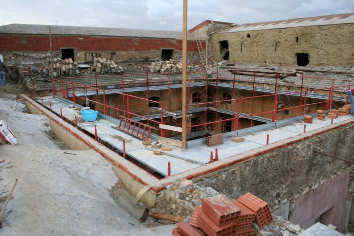
CNR – Advisory Committee on Technical Recommendations for Construction

                          Copyright owned
                                  by
                    The National Research Council

No part of this publication may be stored in a retrieval system, or
            transmitted in any form or by any means
       – electronic, mechanical, recording, or otherwise –
               without the prior written permission
            of the Italian National Research Council.
        The reproduction of this document is permitted
                for personal, non-commercial use.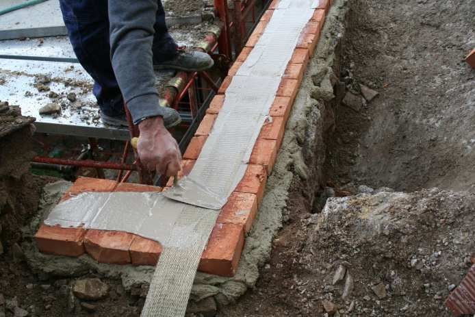
CNR-DT 215/2018

                                                           CONTENTS

1 INTRODUCTION ......................................................................................................................... 1
  1.1 INTRODUCTION TO THE CNR-DT 215/2018 DOCUMENT .......................................... 1
  1.2 PURPOSE OF THE GUIDELINE ........................................................................................ 3
  1.3 SYMBOLS............................................................................................................................. 4

2 FRCM MATERIALS FOR STRUCTURAL STRENGTHENING ......................................... 8
  2.1 INTRODUCTION ................................................................................................................. 8
  2.2 REVIEW OF SIGNIFICANT APPLICATIONS .................................................................. 9
   2.2.1 Applications on masonry structures .................................................................................. 9
      2.2.1.1 Strengthening of masonry panels ............................................................................... 9
      2.2.1.2 Strengthening of vaults and arches ............................................................................ 9
      2.2.1.3 Floor and roof ring beams ........................................................................................ 11
      2.2.1.4 Confinement of masonry columns ........................................................................... 13
   2.2.2 Applications on reinforced concrete structures ............................................................... 13
      2.2.2.1 Flexural strengthening of beams, columns and floor joists ..................................... 13
      2.2.2.2 Shear strengthening of beams and columns ............................................................. 14
      2.2.2.3 Confinement of columns .......................................................................................... 15
      2.2.2.4 Strengthening of beam-column joints ...................................................................... 16
      2.2.2.5 Shear strengthening of reinforced concrete walls .................................................... 17
      2.2.2.6 Slab strengthening (anti-detachment) ...................................................................... 17
      2.2.2.7 Infill walls strengthened against overturning ........................................................... 18
      2.2.2.8 Bridge strengthening ................................................................................................ 19
  2.3 MECHANICAL PROPERTIES OF THE STRENGTHENING SYSTEM ........................ 20

3 BASIC     CONCEPTS          FOR        THE             DESIGN                OF          STRENGTHENING
  INTERVENTIONS AND SPECIAL DESIGN PROBLEMS.................................................. 22
  3.1 MECHANICAL PROPERTIES OF THE STRENGTHENING SYSTEM IN
        DESIGN AND VERIFICATION PROBLEMS .................................................................. 22
  3.2 DESIGN VALUES .............................................................................................................. 23
   3.2.1 Verification in the case of fire ......................................................................................... 24

4 STRENGTHENING OF MASONRY STRUCTURES ........................................................... 25
  4.1 IN-PLANE STRENGTHENING OF WALLS .................................................................... 25
   4.1.1 Shear Capacity ................................................................................................................ 25
   4.1.2 Combined axial and bending moment capacity .............................................................. 27
  4.2 STRENGTHENING OF MASONRY PANELS FOR OUT-OF-PLANE LOADS ............ 28
  4.3 CROWNING BEAMS IN FRCM-REINFORCED MASONRY ........................................ 29
  4.4 CONFINEMENT OF MASONRY COLUMNS UNDER AXIAL COMPRESSION ........ 30
   4.4.1 Confinement of circular columns .................................................................................... 31
   4.4.2 Confinement of rectangular columns .............................................................................. 32
  4.5 SIMPLE- AND DOUBLE-CURVATURE STRUCTURES ............................................... 33
   4.5.1 Single curvature structures .............................................................................................. 34
      4.5.1.1 Reinforcement identification and assessment through the kinematic approach ...... 34
      4.5.1.2 Reinforcement identification and assessment through the static approach.............. 35
   4.5.2 Barrel vaults .................................................................................................................... 36
   4.5.3 Double curvature structures ............................................................................................ 36

5 STRENGTHENING OF REINFORCED CONCRETE STRUCTURES.............................. 37
  5.1 FLEXURAL STRENGTHENING ...................................................................................... 37

                                                                      i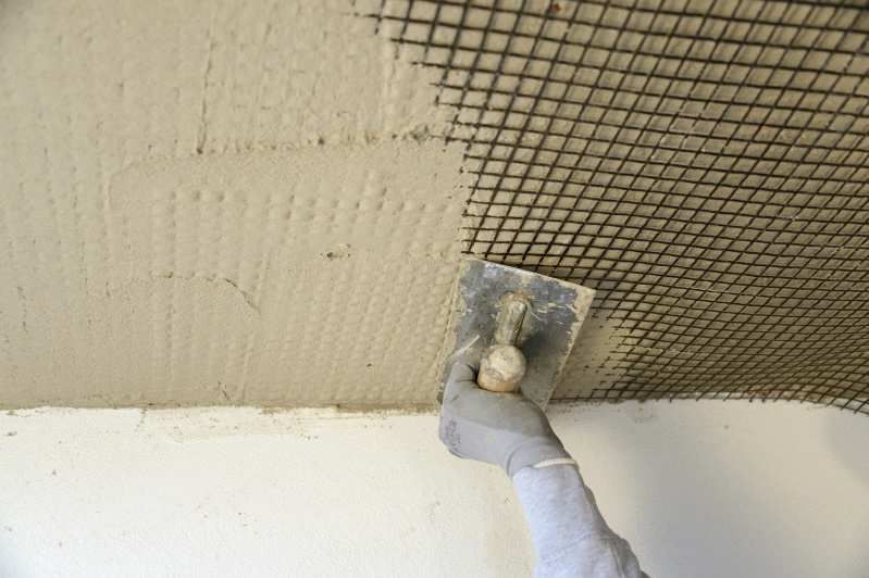
CNR-DT 215/2018

     5.1.1 Ultimate limit state (ULS) ............................................................................................... 37
     5.1.2 Serviceability limit state (SLS) ....................................................................................... 37
    5.2 SHEAR STRENGTHENING .............................................................................................. 38
     5.2.1 Effective design strength ................................................................................................. 39
    5.3 CONFINEMENT OF REINFORCED CONCRETE COLUMNS SUBJECTED TO
          CENTRED COMPRESSION .............................................................................................. 40
     5.3.1 Confinement of prismatic cross-section columns ........................................................... 40

6 DETAILING ................................................................................................................................ 41

7 MAINTENANCE AND REPAIR .............................................................................................. 43

8 CONTROL ................................................................................................................................... 44
  8.1 CONSTRUCTION CHECKS ON SITE.............................................................................. 44
  8.2 QUALITY CONTROL OF THE STRENGTHENING SYSTEM ...................................... 44
   8.2.1 Semi-destructive tests...................................................................................................... 44
   8.2.2 Non-destructive tests ....................................................................................................... 45

9 EXPERIMENTAL TESTS ON STRUCTURAL ELEMENTS .............................................. 47

10 REFERENCES ............................................................................................................................ 49

11 NUMERICAL EXAMPLES....................................................................................................... 56
   11.1 IN-PLANE STRENGTHENING OF MASONRY WALLS ............................................... 56
    11.1.1 Shear capacity ................................................................................................................. 56
    11.1.2 In-plane combined axial and bending moment capacity ................................................. 58
   11.2 STRENGTHENING OF MASONRY PANELS FOR OUT-OF-PLANE LOADS ............ 62
   11.3 CONFINEMENT OF MASONRY COLUMNS ................................................................. 70
    11.3.1 Example 1........................................................................................................................ 70
    11.3.2 Example 2........................................................................................................................ 72
   11.4 STRENGTHENING OF AN RC BEAM ............................................................................ 73
    11.4.1 Design of the flexural strengthening ............................................................................... 73
    11.4.2 Design of the shear strengthening ................................................................................... 78
   11.5 CONFINEMENT OF A REINFORCED CONCRETE COLUMN .................................... 79

12 APPENDIX 1: ON THE IN-PLANE AXIAL-MOMENT RESISTANCE
   CALCULATION ......................................................................................................................... 81

13 APPENDIX 2: ASSESSMENT OF SOLIDARITY BETWEEN REINFORCEMENT
   AND STRUCTURE IN THE CASE OF CURVED SUPPORT .............................................. 85

                                                                       ii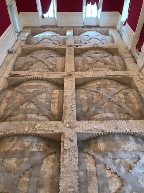
CNR-DT 215/2018

1 INTRODUCTION

      1.1 INTRODUCTION TO THE CNR-DT 215/2018 DOCUMENT
The FRCM (Fibre-Reinforced Cementitious Matrix/Mortar) composites are nowadays used in struc-
tural rehabilitation interventions, more and more frequently, instead of classic FRP fibre reinforced
composites (Fibre Reinforced Polymer), made with long glass, carbon or aramid fibres immersed in
polymeric matrices (such as epoxy resins). In international literature the first are also called TRC
(Textile Reinforced Concrete), TRM (Textile Reinforced Mortars), FRM (Fabric Reinforced Mor-
tar) or even IMG (Inorganic Matrix-Grid Composites). In the following, since the acronym FRCM
has been adopted in already approved Italian ministerial documents, it is preferred to continue using
the same acronym.
FRCM composites are the result of coupling nets, made with the same fibres mentioned above, or
with others which have appeared more recently on the building materials market, with an inorganic
matrix based on lime or cement mortar. Innovative fibres include basalt, PBO (Polyparaphenylene
benzobisoxazole) and steel. In particular, this last material, very common in the construction field,
is proposed again for use in FRCMs, in a version with highly enhanced mechanical performance,
thanks to a particular processing process.
The inorganic matrix has numerous advantages over the organic FRP matrix, especially for applica-
tions to masonry structures, given its greater affinity with this type of substrate. At the moment
some guidelines are available in the international field for the qualification of FRCMs and for the
design of structural reinforcement interventions carried out with such materials. In this connection
the US acceptance criteria (ACI 434 - Acceptance Criteria for Masonry and Concrete Strengthen-
ing Using Fiber-Reinforced Cementitious Matrix (FRCM) Composite Systems, issued by ICC Eval-
uation Service, 2018) and the design guidelines (RILEM TC 250-CSM & ACI 549 - Guide to De-
sign and Construction of Externally Bonded Fabric-Reinforced Cementitious Matrix (FRCM) and
Steel Reinforced Grout (SRG) Systems for Repair and Strengthening Masonry Structures, pending
approval) can be mentioned.
In recent years, the scientific interest in the innovative applications of FRCMs for structural rehabil-
itation, on the one hand, and the special nature of the widely varied Italian building heritage on the
other, have attracted the interest of numerous researchers operating in the fields of Structural Me-
chanics, Construction, Structural Rehabilitation and Seismic Engineering.
It is clear that the drafting of an Italian Guideline for the design and construction of strengthening
interventions with FRCMs could no longer be postponed; above all, the drafting of a wide ranging
document usable for the different types present in the national building heritage, from the masonry
to the concrete constructions, as well as for the many FRCM products currently present on the na-
tional market that are different in nature of the matrix and the net reinforcement.
The CNR, through its Advisory Committee on Technical Recommendations for Construction,
promptly felt this need and made efforts to satisfy it by setting up a Working Group in June 2016
with the task of drawing up a Guideline for the design and construction of externally bonded fibre
reinforced inorganic matrix systems for strengthening existing structures.
In July 2017, the CNR Advisory Committee approved a first draft of this Technical Document on a
proposal from the Working Group. Subsequently, the Working Group expanded to include all inter-
ested Italian researchers already scientifically committed to the topic, and benefited from the inval-
uable contribution of the FRCM manufacturers. It was thus possible to draw up the present version
of the Technical Document, broader than the initial draft and characterized by more advanced ap-
plications and more sophisticated approaches which are at the frontier of current international re-
search on the topic of structural reinforcement with FRCM.

                                                   1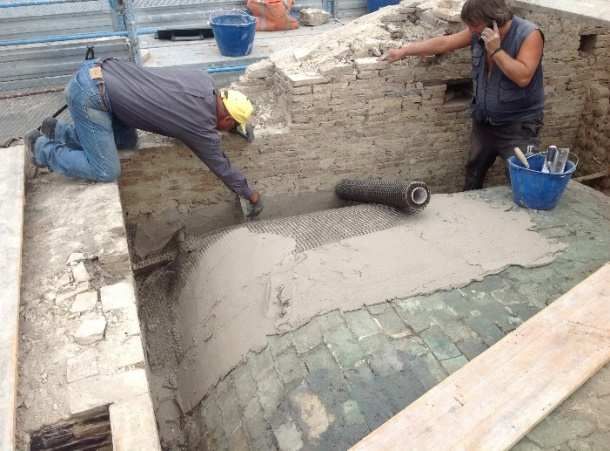
CNR-DT 215/2018

The first draft, mentioned above, is the basis of the Guideline prepared and recently approved (Jan-
uary 2019) by the Italian Ministry of Infrastructure and Transport (MIT) for the identification of
procedures for the qualification of FRCMs.
A valid contribution to the drafting of this Guideline was provided by the results of a round robin
promoted by the RILEM TC 250-CSM between the laboratories of different European Universities.

This Technical Document has been prepared by a Working Group whose members are:

AIELLO Prof. Maria Antonietta       - Università del Salento
ASCIONE Prof. Luigi                 - Università di Salerno
ASSOCOMPOSITI                       - Politecnico di Milano
BARATTA Prof. Alessandro            - Università “Federico II”- Napoli
BILOTTA Ing. Antonio                - Università “Federico II”- Napoli
CAMATA Prof. Guido                  - Università “G. d’Annunzio” - Chieti-Pescara
BORRI Prof. Antonio                 - Università di Perugia
CARLONI Prof. Christian             - Università di Bologna
CAROZZI Arch. Francesca Giulia      - Politecnico di Milano
CASADEI Ing. Paolo                  - Kerakoll S.p.A. - Sassuolo (MO)
CLAURE Prof. Guillermo              - Università di Miami, Coral Gables, Florida - USA
CERSOSIMO Ing. Giuseppe             - Interbau S.r.l.- Milano
COSENZA Prof. Edoardo               - Università “Federico II”- Napoli
CORBI Geol. Ileana                  - Università “Federico II”- Napoli
CORBI Prof. Ottavia                 - Università “Federico II”- Napoli
D’ANTINO Ing. Tommaso               - Politecnico di Milano
de FELICE Prof. Gianmarco           - Università Roma Tre - Roma
DE SANTIS Ing. Stefano              - Università Roma Tre - Roma
DI LUDOVICO Prof. Marco             - Università “Federico II”- Napoli
DI PRISCO Prof. Marco               - Politecnico di Milano
FERRACUTI Prof. Barbara             - Università “Niccolò Cusano” - Roma
FOCACCI Prof. Francesco             - Università eCampus
FRASSINE Prof. Roberto              - Politecnico di Milano
GIACOMIN Ing. Giorgio               - G&P Intech S.r.l. - Altavilla Vicentina (VI)
GREPPI Ing. Roberto                 - T.C.S. S.r.l. - Montichiari (BS)
LA MENDOLA Prof. Lidia              - Università di Palermo
LIGNOLA Prof. Gian Piero            - Università “Federico II”- Napoli
MANTEGAZZA Dott. Giovanni           - Mahac S.r.l., Technical Manager &Co-Founder - Milano
MAZZOTTI Prof. Claudio              - Università di Bologna
MONTALBANO Ing. Antonino            - Sika Italia S.p.a. - Milano
MORANDINI Ing. Giulio               - Mapei S.p.a. - Milano
NANNI Prof. Antonio                 - Università di Miami, Miami, Florida
NERILLI Ing. Francesca              - Università “Niccolò Cusano” – Roma
NICOLETTI Ing. Andrea               - BASF Construction Chemical Italia S.p.A., Treviso
NIGRO Prof. Emidio                  - Università “Federico II”- Napoli
OCCHIUZZI Prof. Antonio             - CNR-ITC, San Giuliano Milanese
PECCE Prof. Maria Rosaria           - Università del Sannio - Benevento
PELLEGRINO Prof. Carlo              - Università di Padova
POGGI Prof. Carlo                   - Politecnico di Milano
PROTA Prof. Andrea                  - Università “Federico II”- Napoli
REALFONZO Prof. Roberto             - Università di Salerno
ROSATI Prof. Luciano                - Università “Federico II”- Napoli

                                                 2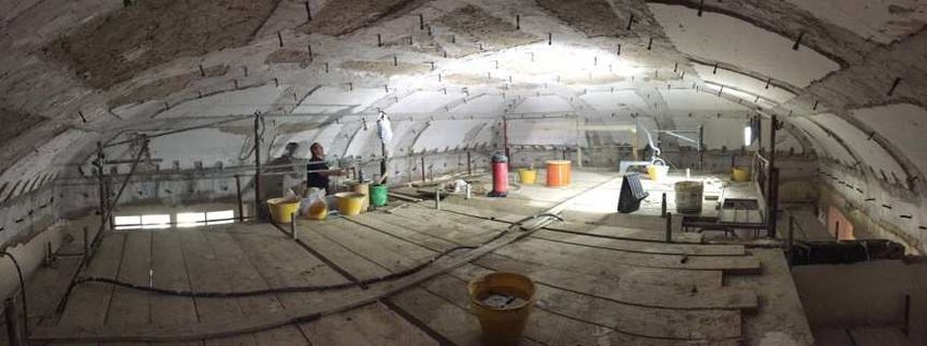
CNR-DT 215/2018

SACCO Prof. Elio                     - Università “Federico II”- Napoli
SAVOIA Prof. Marco                   - Università di Bologna
ZAMPA Ing. Andrea                    - Fibre Net S.r.l. - Udine

Coordinator:
ASCIONE Prof. Luigi

Technical Secretariat:
LIGNOLA Prof. Gian Piero

This Technical Document has been approved by the Advisory Committee on Technical Recommen-
dation for Construction as a draft version on 23/10/2018 and submitted for public hearing. At the
conclusion of the public hearing, with the resulting modifications, it was approved in a definitive
version on 06.02.2019 by the Advisory Committee on Technical Recommendations for Construc-
tion, composed as follows:

ANGOTTI Prof. Franco                                 - Università di Firenze
AURICCHIO Prof. Ferdinando                           - Università di Pavia
ASCIONE Prof. Luigi                                  - Università di Salerno
BARATTA Prof. Alessandro                             - Università “Federico II” – Napoli
COSENZA Prof. Edoardo                                - Università “Federico II” – Napoli
DI PRISCO Prof. Marco                                - Politecnico di Milano
LAGOMARSINO Prof. Sergio                             - Università di Genova
MACERI Prof. Franco, Presidente                      - Università “Tor Vergata” – Roma
MANCINI Prof. Giuseppe                               - Politecnico di Torino
MAZZOLANI Prof. Federico Massimo                     - Università “Federico II” – Napoli
OCCHIUZZI Prof. Antonio                              - Consiglio Nazionale delle Ricerche, ITC
PINTO Prof. Paolo Emilio                             - Università “La Sapienza” – Roma
POGGI Prof. Carlo                                    - Politecnico di Milano
PROTA Prof. Andrea                                   - Università “Federico II” – Napoli
ROYER CARFAGNI Prof. Gianni                          - Università di Parma
SAVOIA Prof. Marco                                   - Università di Bologna
SCARPELLI Prof. Giuseppe                             - Università Politecnica delle Marche
SOLARI Prof. Giovanni                                - Università di Genova
URBANO Prof. Carlo                                   - Politecnico di Milano
ZANON Prof. Paolo                                    - Università di Trento

The same Committee has approved the English version on the 6th of February 2020.

      1.2 PURPOSE OF THE GUIDELINE
The purpose of this guideline is to provide, within the framework of the Italian regulations, a docu-
ment for the design and construction of externally bonded FRP systems for strengthening existing
structures. A guideline, by definition is not a binding regulation, but merely represents an aid for
practitioners interested in the field of the strengthening with FRCMs. Nevertheless, the responsibil-
ity remains with the user of this guide.

The following topics will be addressed:

- FRCM materials

                                                 3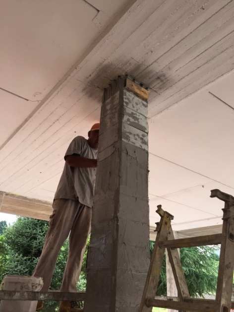
CNR-DT 215/2018

- Review of significant applications
- Basic concepts of reinforcement with FRCM and special problems
- Reinforcement of masonry structures
- Reinforcement of RC structures
- Construction details
- Maintenance and repair
- Control and monitoring
- Experimental tests on structural models
- Literature references
- Worked examples

The Guideline also contains the following Appendices:

- Appendix 1, Calculation of the ultimate resistant moment (combined axial and bending) in the
  plane
- Appendix 2, Assessment of solidarity between reinforcement and structure in the case of curved
  support

     1.3 SYMBOLS

The meaning of the main symbols utilized in this Guideline are as follows.

General notations
(.) c   Value of quantity (.) for concrete
(.) cc  Value of quantity (.) for confined concrete
(.)d    Design value of quantity (.)
(.) f   Value of quantity (.) referred to the fibre (or grid) itself
(.)k    Characteristic value of quantity (.)
(.) m   Value of quantity (.) for masonry
(.) mat Value of quantity (.) referred to the matrix
(.) mc Value of quantity (.) for confined masonry
(.) R   Value of quantity (.) as resistance
(.)s    Value of quantity (.) for steel
(.)S    Value of quantity (.) as stress

Uppercase Roman letters
Am    Cross-sectional area of confined masonry column
Ac    Cross-sectional area of confined concrete column, without steel reinforcement
As    Area of steel reinforcement
Af    Area of dry fibre
Ef    Young’s modulus of elasticity of dry fibre
E1    Young’s modulus of elasticity of uncracked FRCM
Em    Young’s modulus of elasticity of masonry
D     Diameter of circular columns, or diagonal of rectangular/square cross sections
H     Length of masonry panel (height of cross section)

                                                     4
CNR-DT 215/2018

Lmax        Maximum anchoring length
M Rd        Design flexural capacity of strengthened member
M Sd        Factored moment
M 0d        Design flexural capacity before strengthening
M 1d        Design flexural capacity after strengthening
N R cc,d    Design axial capacity of confined concrete member
N R m c,d   Design axial capacity of confined masonry member
N Sd        Factored axial force
No          Axial force to assess simple- and double-curvature structures
Nm          Compressive force on masonry
Nf          Tensile force in strengthening system
FC          Confidence factor
Fm          Resultant of compressive force on masonry, calculated with stress-block
Ff          Resultant of tensile force transferred by reinforcement
Vt,R        In-plane shear capacity of strengthened masonry
VRd         Shear capacity of concrete member
V R d,c     Shear capacity limited by compressed concrete
V R d,f     FRCM contribution to the shear capacity
V Rd,m      Out-of-plane shear capacity of strengthened masonry
V R d ,s    Steel contribution to the shear capacity
V t,f       FRCM contribution to the shear capacity Vt,R
Vt          Un-Reinforced masonry contribution to the shear capacity Vt,R
V t,c       Diagonal crushing threshold of masonry
Xd          Design value of generic property
 Xk         Characteristic value of generic property

Lowercase Roman letters
t        Thickness of masonry panel
t mat    Thickness of FRCM matrix
tf       Equivalent thickness of FRCM provided by manufacturer
t2f      = 2 ⋅ tf when reinforcement is applied on both sides of member
tVf      Equivalent thickness of fibres parallel to shear force
nf       Total number of FRCM layers
b, h     Dimensions of confined member cross section
bf       Dimension of FRCM in the bending plane
b ', h ' Dimensions of confined member cross section, minus rounding corners
d        Effective height of section
df       Distance between the extreme compressed masonry and the extreme FRCM under tension
 f ccd   Design strength of confined concrete
 f cd    Design concrete compressive strength
 ffed       Effective design strength of reinforcement
 f1         Confining lateral pressure

                                                       5
CNR-DT 215/2018

 f1,eff     Effective confining pressure
 f c,mat    Characteristic compressive strength of the matrix
 f mcd      Design compressive strength of FRCM-confined masonry
f md        Design compressive strength of unconfined masonry
f vd        Design shear strength of masonry
f yd        Design yield strength of steel reinforcement
gm          Masonry density in kg/m3 (confinement)
hw          Height of the beam web
kH          Coefficient of efficiency in the horizontal direction (confinement)
k mat       Dimensionless coefficient to account for inorganic matrix (confinement)
k'          Dimensionless coefficient for strength increment (confinement)
i           Spacing of connectors
led         Effective anchoring length
l           Length of connectors
ℓ           Height of masonry panel
ℓf          Design dimension of FRCM for shear
yn          Distance from extreme compression fibre to neutral axis
pf          Spacing of reinforcements
qu,f        Stress limit for dry fibre to apply simplified method in Table 4.1
rc          Corner rounding radius
r           Curvature radius for simple- and double-curvature structures

Lowercase Greek letters
γm   Partial factor for materials and products
γ rt        Partial factor to assess simple- and double-curvature structures
γ Rd        Partial factor for resistance models
εlim,conv Conventional strain limit (end condition)
σlim,conv Conventional stress limit (end condition)
α      Amplification coefficient for substrate debonding and/or fibre/matrix intermediate slip
α1 ,α2 Strength increment coefficient (confinement)
α3 ,α4 Strength increment coefficient (confinement)
αt         Coefficient to account for reduced tensile strength of fibres when stressed in shear
ε lim,conv
   (α)
           Conventional strain limit (intermediate condition)
σlim,conv
  (α)
            Conventional stress limit (intermediate condition)
εu          Ultimate tensile strain of FRCM
σu          Ultimate tensile stress of FRCM
σo          Normal stress
σ max       Maximum interface stress to assess simple- and double-curvature structures
σr          Stress orthogonal to interface to assess simple- and double-curvature structures
τ 0d        Design shear strength of masonry
τr          Interface shear stress to assess simple- and double-curvature structures

                                                       6
CNR-DT 215/2018
σ r0 Debonding interface capacity to assess simple- and double-curvature structures
σ rt Minimum tensile capacity to assess simple- and double-curvature structures
εu,f Ultimate tensile strain of dry fibres
σu,f Ultimate tensile stress of dry fibres
η Conversion factor
ηa Environmental conversion factor
θ Shear crack angle with respect to longitudinal axis of members
β Fibre angle with respect to longitudinal axis of members
βο Reductive coefficient to assess simple- and double-curvature structures
σ fd Design strength of FRCM
ε fd Design strain of FRCM
εfd,rid Reduced design strain of FRCM reinforcement for confined members
εmu Ultimate compressive strain of masonry
εm Ultimate compressive strain of masonry with linear behaviour
ρmat Matrix reinforcement ratio (confinement)
7CNR-DT 215/2018
2 FRCM MATERIALS FOR STRUCTURAL STRENGTHENING
2.1 INTRODUCTION
FRCM materials – hereinafter also referred to as FRCM strengthening systems or, more simply,
FRCM systems or also FRCM reinforcements are obtained by using reinforcement grids made of
aramid, basalt, carbon, PBO and glass bundles/yarns or by using unidirectional high-strength steel
cords; in particular, steel yarns are used in the form of small strands in order to obtain corrugated
surfaces which promote bonding between the reinforcement and matrix. In the following, in order to
refer to the strengthening grids, the terms “fabrics” or “textiles”, which are commonly used, will al-
so be indifferently adopted.
Grids and strands are combined with inorganic matrices, made for example with lime- or cement-
based binders, with the possible addition of additives. In the case of organic additives, it is recom-
mended that the organic component does not exceed 10% by weight of the inorganic binder. In fact,
it should be kept in mind that as the overall percentage of organic components increases the FRCM
system can undergo a degradation of permeability, durability and fire behaviour properties.
In general, FRCM strengthening systems, in the case of a single-ply fabric application, have a
thickness ranging between 5 and 15 mm, excluding the levelling of the substrate. In the case of mul-
tiple plies, thickness increases, but it is usually not greater than 30 mm. The net distance between
the lateral surfaces of the bundles/yarns or strands, along the directions in which they are devel-
oped, does not usually exceed 2 times the thickness of the mortar and in any case it cannot be great-
er than 30 mm.
The high strength-to-weight ratio of FRCM systems makes it possible to enhance the mechanical
performance of the strengthened structural element, essentially being able to withstand the tensile
stresses without increasing its mass or significantly changing its stiffness.
In general FRCM reinforcements demonstrate good chemical-physical compatibility with masonry
and concrete substrates and a certain degree of vapour permeability; moreover, they can be prepared
and applied in a simple way by using basically traditional procedures, even on wet surfaces. Due to
their mechanical properties, FRCM reinforcements are specifically indicated for applications requir-
ing limited deformations, as typically occurs for strengthening of masonry.
The following paragraphs explain the design rules related to the main structural applications for
which predictive models widely shared by the technical and scientific community, both nationally
and internationally, are available.
Further applications shall necessarily be supported by in-depth preliminary investigations per-
formed in laboratory on full scale structural elements and by numerical verifications.
For the aspects related to identification and qualification of the system, as well as for those related
to durability, transport, storage, handling, use, see the documentation produced for the CE marking
or the Technical Assessment Certificates (CVT) and the compulsory installation manuals for these
materials, according to the Guideline recently approved by the Italian Ministry of Infrastructures
and Transportation (MIT – January 2019) and entitled: Linea Guida per la identificazione, la quali-
ficazione ed il controllo di accettazione di compositi fibrorinforzati a matrice inorganica (FRCM)
da utilizzarsi per il consolidamento strutturale di costruzioni esistenti. It deals with the same types
of strengthening systems covered by this document, and limits use, for glass fibre grids, to AR (Al-
kali Resistant) fibres only.
In the remainder of the document, the terms “dry fabric” or “dry textile” will refer to fabric/textile
not embedded inside the inorganic matrix, thus including coated or pre-impregnated fabrics or
grids, according to the MIT Guideline.
The unified approach proposed in the document makes it possible to apply the same rules to the
wide range of FRCM materials, differing in their types of strengthening grids and matrixes, availa-
ble in the Italian market together with the considerable variety of supports present in the national
8CNR-DT 215/2018
building heritage. The common design approach represents a particular aspect of the document and
the main difficulty encountered in its drafting, something which has already happened in the im-
plementation of the qualification guideline.
It will be responsibility of the technicians in charge of design and construction supervision to
choose, from the systems available in the market, the most suitable type of reinforcement for the
specific application, taking into account the matrix and grid properties.
Finally, for the aspects related to acceptance criteria at the construction site, the reader can refer to
the current technical regulations and to the previously introduced MIT Guideline.
2.2 REVIEW OF SIGNIFICANT APPLICATIONS
Some significant applications related to strengthening of masonry and RC structures with FRCM
systems are reported below (Figures 2.1 – 2.22). They introduce the reader to the wide range of pos-
sible effective applications that can be developed with this type of system.
2.2.1 Applications on masonry structures
2.2.1.1 Strengthening of masonry panels
The shear and combined axial and bending moment capacity of a masonry wall can be increased by
applying a FRCM strengthening system on wall surfaces and by adopting a continuous or discon-
tinuous layout.
Figure 2.1 – Strengthening of masonry walls with basalt fibre grids.
2.2.1.2 Strengthening of vaults and arches
Vaults and masonry arches can be strengthened by applying FRCMs to both their extrados and in-
trados. In both cases, the aim is to compensate the lack of tensile capacity of the masonry structure
preventing the opening of macro-cracks.
The layout of the reinforcement can be continuous or discontinuous and can be connected to the
surrounding walls and to the vault itself by adhesion and also with special connectors.
When possible, this type of reinforcement is generally combined with the construction of small
stiffening masonry walls at the extrados and with the insertion of steel ties.
9CNR-DT 215/2018
Figure 2.2 – Extradoxal strengthening of a single-leaf vault with extensive application of basalt fi-
bre grid and hydraulic lime mortar.
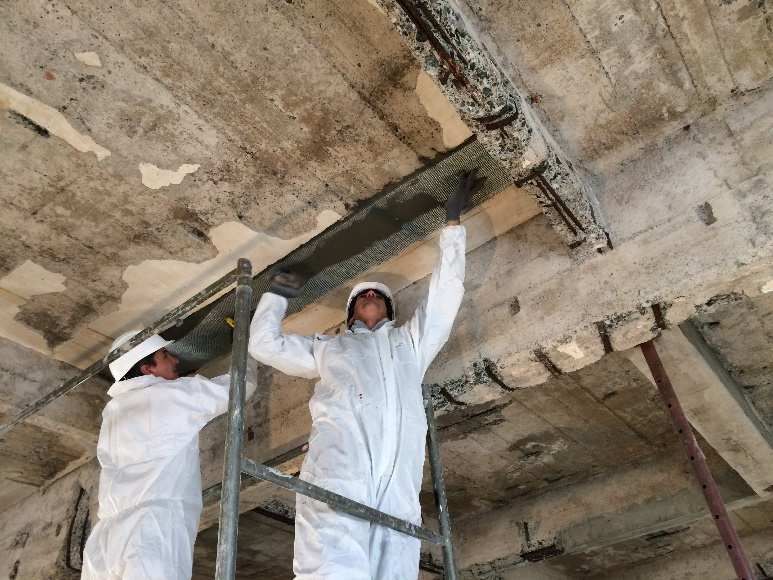
Figure 2.3 – Application of unidirectional galvanized steel fibre strips and mortar for the extradoxal
strengthening of masonry vaults.
10CNR-DT 215/2018
(a)
(b)
Figure 2.4 – (a) Intradoxal strengthening of a barrel vault trough application of ultra-high strength
unidirectional galvanized steel fibre strips together with natural hydraulic lime mortar; (b) Extra-
doxal strengthening of cross vaults by applying ultra-high strength unidirectional galvanized steel
fibre strips together with hydraulic lime mortar.
Figure 2.5 – Intradoxal strengthening of a masonry vault with AR glass fibre grid and mortar.
2.2.1.3 Floor and roof ring beams
In order to increase the collapse multipliers associated with overturning mechanisms of wall macro-
elements an external ring element made of fabric sheets encircling the building can be built.
It is also possible to construct ring beams at the roof level made of masonry reinforced by compo-
site fabric inserted inside the bed mortar joints.
11CNR-DT 215/2018
Figure 2.6 – Floor ring beams built with PBO and steel fabrics.
Figure 2.7 – Roof ring beams built with steel fabrics.
Figure 2.8 – Roof ring beams built with AR glass fibre grids.
12CNR-DT 215/2018
2.2.1.4 Confinement of masonry columns
Wrapping of elements subjected to uniaxial compression or to compression and minimal bending
makes it possible to increase the ductility of the element and to increase its load-bearing capacity.
The layout of the wrapping can be continuous or discontinuous.
Figure 2.9 – Confinement of masonry column with AR glass fibre grid.
2.2.2 Applications on reinforced concrete structures
2.2.2.1 Flexural strengthening of beams, columns and floor joists
Flexural strengthening is achieved by applying fabric strips to the side of the element subject to ten-
sile stresses. Using this method the deflection under service loads can be reduced, although often
not very substantially, and crack openings can be limited.
Figure 2.10 – Flexural strengthening of a beam and of a column with PBO fibre grid.
13CNR-DT 215/2018
Figure 2.11 – Beam flexural strengthening with ultra-high strength unidirectional galvanized steel
fibre strips and cementitious mortar.
2.2.2.2 Shear strengthening of beams and columns
Shear strengthening is achieved by applying fabric strips to the lateral surfaces of the element to be
strengthened. The reinforcement can be continuous, with the application of each fabric sheet adja-
cent to the previous one, or discontinuous, interspersing the strengthening strips with empty spaces.
Furthermore, the element can be reinforced by completely wrapping the cross-section or with U-
jacketing and possibly using connectors.
Figure 2.12 – Shear strengthening of a beam with PBO fibre grid.
14CNR-DT 215/2018
2.2.2.3 Confinement of columns
As for masonry, wrapping of elements subjected to uniaxial compression or to compression and
small bending allows the ductility of the element and its load-bearing capacity to be increased.
Wrapping can have a continuous or a discontinuous layout.
Figure 2.13 – Confinement of a column by means of ultra-high strength unidirectional galvanized
steel fibre strips and cementitious mortar.
Figure 2.14 – Confinement of a column with unidirectional galvanized steel fibre strips and mortar.
15CNR-DT 215/2018
2.2.2.4 Strengthening of beam-column joints
The ductility of beam-columns joints can be increased by continuously wrapping the extremities of
the elements connected in the joint.
Figure 2.15 – Strengthening of beam-columns joints.
Figure 2.16 – Strengthening of beam-columns joints with unidirectional galvanized steel fibre strips
and mortar.
16CNR-DT 215/2018
2.2.2.5 Shear strengthening of reinforced concrete walls
Figure 2.17 – Shear strengthening of reinforced concrete walls.
2.2.2.6 Slab strengthening (anti-detachment)
Figure 2.18 – Slab strengthening (anti-detachment).
17CNR-DT 215/2018
Figure 2.19 – Slab reinforcement (anti-detachment) with AR glass fibre grid and mortar.
2.2.2.7 Infill walls strengthened against overturning
Infill walls can be connected to the structural reinforced concrete frame by applying the strengthen-
ing grid to the infill wall and connecting it to the frame with anchors, or by applying textile sheets
between the frame and the infill wall.
Figure 2.20 – Strengthening of walls against overturning with a FRCM system made of glass grid,
mortar, adhesion promoter and glass fibre connectors.
18CNR-DT 215/2018
Figure 2.21 – Overturning protection of infill walls with different types of grids and anchors.
2.2.2.8 Bridge strengthening
Figure 2.22 – Intradoxal strengthening of a concrete arch bridge with PBO grids.
19CNR-DT 215/2018
2.3 MECHANICAL PROPERTIES OF THE STRENGTHENING SYSTEM
The typical stress-strain behaviour of a FRCM system subject to uniaxial tensile force can be de-
scribed by considering three consecutive branches (Figure 2.23), corresponding, respectively, to the
uncracked phase (Stage A), to the crack development phase (Stage B) and to the fully cracked phase
(Stage C).
Figure 2.23 – Typical constitutive law of a FRCM coupon subject to uniaxial tensile test (Af area of
dry fabric/textile).
This diagram is not sufficient to characterize the mechanical behaviour of an FRCM system because
a number of different failure modes may occur related to the reinforcement in a strengthened struc-
tural element as a result of substrate-strengthening system interaction; they are listed below and de-
scribed in Figure 2.24:
A. debonding with cohesive failure within the substrate of the reinforcement;
B. debonding at the matrix-to-support interface;
C. debonding at the matrix-to-textile interface;
D. slippage of the textile within the matrix;
E. slippage of the textile and cracking of the outer layer of mortar;
F. tensile failure of the textile.
Figure 2.24 – Failure modes.
20CNR-DT 215/2018
For this reason, mechanical characterization shall also include, in addition to the tensile test of the
FRCM system and of the dry textile, the bond test and possibly any other appropriate tests depend-
ing on the specific characteristics of the system.
According to the present Guideline, FRCM strengthening systems have to be characterized such
that the following mechanical properties can be used:
a) conventional stress limit, σlim,conv (characteristic value), conventional strain limit, εlim,conv , as defined
further below (both properties depend on the substrate);
b) tensile stiffness of the sample in the stage A, if detectable ( E1 , mean value);
c) ultimate tensile stress σ u (characteristic value) and ultimate tensile strain ε u (mean value) of the
FRCM composite at failure;
d) ultimate tensile stress, σ u ,f (characteristic value) of the dry textile (failure);
e) elastic modulus Ef of the dry textile (mean value);
f) ultimate tensile strain, ε u,f , of the dry textile ( ε u,f = σ u,f E f );
g) compressive strength of the matrix/mortar, f c,mat , intended as characteristic or nominal (the latter
assumed as characteristic).
The definition of the above qualification parameters represents an original contribution of the mem-
bers of two working groups, from CNR and MIT, achieved through a structured work of progres-
sive refinement and also making use of the results from a Round Robin Test activity carried out by
the laboratories of different European Universities, promoted by RILEM TC 250-CSM.
Stresses are conventionally referred to the cross-sectional area of the dry textile ( Af ), regardless of
the presence of the matrix/mortar.
The equivalent fibre thickness of the FRCM system, t f , provided by the Manufacturer (technical
datasheet) is defined as follows: the equivalent fibre thickness of a composite grid along the direc-
tion of the weft (warp) is the ratio between the density of the yarns/strands only in the direction of
the weft (warp) and the specific weight of the fibres which constitute the weft (warp).
In the case of a grid having the same number and the same type of yarns/strands along the weft and
warp directions, the equivalent fibre thickness will be the same along those two directions. In other
cases, the equivalent thickness is different depending on whether the direction along the weft or the
warp is considered.
21CNR-DT 215/2018
3 BASIC CONCEPTS FOR THE DESIGN OF STRENGTHENING
INTERVENTIONS AND SPECIAL DESIGN PROBLEMS
3.1 MECHANICAL PROPERTIES OF THE STRENGTHENING SYSTEM IN
DESIGN AND VERIFICATION PROBLEMS
The conventional stress limit σlim,conv represents the bond strength of a specific FRCM system and is
evaluated by means of bond tests, performed on FRCM reinforcements applied to conventional sub-
strates. As such it then depends on the type of substrate and corresponds to the characteristic value
of the peaks of the applied tensile force registered during the tests (refer to the Italian Guideline for
the identification, qualification and acceptance control of FRCM strengthening systems, published
by the Italian Ministry of Infrastructure and Transport (MIT). The conventional strain limit is de-
fined as ε lim,conv = σ lim,conv / E f (Figure 3.1).
The use of the conventional strain limit and of the corresponding conventional stress limit makes it
possible to design strengthening interventions by means of FRCM systems without performing a
specific verification concerning the failure modes related to debonding or to slippage of the textile
within the matrix, typically at the end of the reinforcement. This verification is, however, necessary
when these failure modes can take place. This situation usually occurs when the maximum stress in
the FRCM system is located at its extremities, for instance in interventions involving the flexural
strengthening of beams or panels, especially when subjected to seismic action, or shear strengthen-
ing of reinforced concrete beams.
Failure due to the debonding or to slippage of the textile within the matrix, occurring at the extremi-
ties of the FRCM reinforcement, is prevented if the FRCM system can be extended up to a signifi-
cant distance from the cross-section with maximum tensile stress, for instance, in strengthening of
masonry walls subject to out-of-plane loads or when FRCM systems are applied at the intrados of
reinforced concrete beams to increase their flexural capacity with respect to dead loads.
That being said, for the purposes of this Guideline, the conventional limit values εlim,conv and σlim,conv
represent the parameters to be adopted in the verifications of failure mechanisms located at the ex-
tremities of the FRCM system.
SUBSTRATE
F
δ
F σ
σ u,f
Fmax σ lim,conv
σ lim,conv=Fmax/Af
δ ε lim,conv ε u,f ε
Figure 3.1- Determination of σlim,conv and εlim,conv .
If the above mentioned failure modes due to the debonding or to the slippage of the textile within
the matrix, are located instead in intermediate zones, i.e., along the reinforced element (not at its ex-
22CNR-DT 215/2018
tremities), the tensile failure of the textile occurs for strain values significantly higher than the con-
ventional strain limit.
In this case, the values of the parameters to be adopted in the verifications governed by debonding
or slippage, but located in intermediate zones, are ε lim,conv
(α)
= α ⋅ ε lim,conv and σ lim,conv
(α )
= Ef ⋅ ε lim,conv
(α )
.
The amplification coefficient α can be taken as equal to 1.5 for all the FRCM strengthening sys-
tems, except for those in which the point corresponding to the conventional stress limit σ lim,conv falls
within Stage A of the stress-strain diagram above. For these FRCM systems a value of 1.0 shall be
assumed for the amplification coefficient α .
Higher values of the coefficient α, i.e. greater than 1.5 or 1.0 respectively, can be considered, but
they shall be supported by suitable experimental tests on structural members, as described in § 9.
In any case, the value of σ lim,conv
(α)
shall be smaller than σ u or at least equal to it. The partial safety
factors and conversion factors, mentioned in the following Section, shall be applied to the above
mentioned values.
In the situations governed by the tensile strength of the textile rather than by the debonding of the
FRCM system or by the slippage of the textile within the matrix, the values of the parameters to be
adopted in design problems are the ultimate strain of the dry textile and the corresponding ultimate
stress, ε u,f and σ u,f . Partial safety factors and conversion factors, described in the following Sec-
tion, shall be applied to these values as well.
In some specific applications presented in the following chapters, such as the confinement, the pro-
posed predictive formula, obtained from test databases, have been calibrated on the basis of the ul-
timate strain of the dry textile, which is the qualification parameter often used by researchers to pre-
sent their results.
3.2 DESIGN VALUES
The design value, Xd , of a generic strength or strain property of a FRCM strengthening system can
be expressed as follows:
Xk (3.1)
Xd =η ⋅ .
γm
where η is a suitable conversion factor accounting for special design problems, X k is the charac-
teristic value of the property, and γ m is the corresponding partial factor.
The latter is equal to 1.5 for Ultimate Limit States (ULS) and to 1.0 for Serviceability Limit States
(SLS). For the verifications concerning Ultimate Limit States, the effects of environmental factors
shall be taken into account. In the absence of more specific data, the values of ηa given in Table 3.1
shall be attributed to the conversion factor η , independently of the characteristics of the textile.
Exposure conditions ηa
Internal 0.90
External 0.80
Aggressive environment 0.70
Table 3.1 – Environmental conversion factors.
23CNR-DT 215/2018
Higher values, up to 1.0, may be used if supported by specific laboratory tests performed by the
Manufacturer according to the general principles mentioned in § 9, also taking account of the crack-
ing of the matrix.
As far as the verifications concerning Serviceability Limit States, to be carried out for interventions
on reinforced concrete structures, are concerned, the static fatigue phenomenon shall be taken into
account, as prescribed in § 5.1.2.
3.2.1 Verification in the case of fire
In the event of a fire, the strengthened structure shall be verified without the reinforcing system.
The actions have to be determined with reference to the quasi-permanent combination, and the ca-
pacity of the structural members shall be evaluated with unitary partial factors for materials.
24CNR-DT 215/2018
4 STRENGTHENING OF MASONRY STRUCTURES
Strengthening of masonry structures is one of the most important applications for FRCM systems.
These systems can be extended to the entire surface of the walls or applied in strips, having enough
width to limit the tangential stress at the masonry - reinforcement interface.
Safety checks can be conducted at the ultimate limit state only, as indicated below.
Usually, the increase of design capacity of an element strengthened with FRCM should not be more
than 50% compared to the unreinforced counterpart. This limitation does not apply to seismic ac-
tions.
4.1 IN-PLANE STRENGTHENING OF WALLS
FRCM systems can be adopted to improve the in-plane load bearing capacity of walls. In the case of
masonry with poor mechanical properties, such as for example cavity walls, it is necessary to com-
bine the FRCM strengthening interventions with other types of operations in order to preserve the
structure of the wall and to allow for appropriate stress transfer to the FRCM.
The following paragraphs provide indications for the design and/or checks of strengthening inter-
ventions on walls loaded in their planes in shear or bending.
4.1.1 Shear Capacity
In order to increase the in-plane shear capacity of masonry walls, it is preferable to arrange FRCM
reinforcements symmetrically on both sides, and usually extended to the entire surface with the fi-
bres preferably in both the vertical and horizontal directions. For the design of the shear strengthen-
ing, the area of the fibres arranged parallel to the shear force only is considered; however, to ensure
the effectiveness of such interventions, also after cracking, it is advisable to apply fibres in the or-
thogonal direction.
The shear capacity of the strengthened wall ( Vt,R ) is calculated as the sum of the contribution of un-
reinforced masonry ( V t ), evaluated according to building codes for unreinforced masonry failing
under tension, and the contribution of the reinforcement ( V t,f ).
The latter contribution is evaluated according to:
1 (4.1a)
V t,f = ⋅ nf ⋅ tV f ⋅ ℓ f ⋅ α t ⋅ ε fd ⋅ E f .
γ Rd
where:
-
γRd is a partial safety factor equal to 2, according to current knowledge;
- nf is the total number of reinforcement layers arranged on the sides of the wall;
- tV f is the equivalent thickness of a layer of the fibres arranged in the direction parallel to the
shear force;
- ℓ f is the design dimension of the reinforcement measured orthogonally to the shear force, and in
any case it cannot be assumed as longer than the dimension H of the wall (Figure 4.1).
25CNR-DT 215/2018
Figure 4.1 - FRCM in-plane strengthening of panels: (a) strengthening of pier panel; (b) strengthen-
ing of spandrel panel.
The product n f ⋅ t V f ⋅ ℓ f represents the area of the equivalent cross section of reinforcement effec-
tive in shear, in the direction parallel to the shear force, which intersects a shear crack inclined at
45°. Hence the limit ℓ f ≤ H .
The value of ε fd is derived from ε lim,conv through (3.1). The coefficient α t takes into account the
(α)
reduced tensile strength of the fibres when stressed in shear. Without experimental results, it can be
assumed equal to 0.80.
With a strengthening system applied on one side only of the wall, the shear contribution shall be re-
duced by at least 30% and connectors shall be applied to fix the reinforcement to the wall.
26CNR-DT 215/2018
If fibres orthogonal to the direction of shear are effectively anchored, it should be also checked that
the shear force does not exceed the following diagonal crushing value for masonry:
V t,c = 0 .2 5 ⋅ f m d ⋅ t ⋅ d f , (4.1b)
where:
- t is the thickness of the wall;
- f m d is the design compressive strength of the masonry;
- d f is the distance between the extreme compressed masonry and the extreme FRCM under ten-
sion (fibre direction orthogonal to the shear force - Figure 4.1).
In (4.1b) the properties of unreinforced masonry only are given since it is assumed that the FRCM
does not contribute to the compressive strength of masonry.
In a simplified way, the strengthened masonry capacity can be calculated by multiplying the aver-
age shear stress capacity of unreinforced masonry without normal stresses by appropriate multipli-
cative coefficients. Such coefficients can be used only in the case of masonry having thicknesses
lower than 400 mm, in the case of reinforcements arranged symmetrically over the entire surface of
the two sides of the walls and ensuring that σ u,f tf ≥ qu,f ; coefficients are given in Table 4.1.
qu, f
Masonry Type Corrective coefficient
(N/mm)
Masonry in disorganized stones (pebbles, or errat- 1.5 44.60
ic/irregular stones)
Masonry in rough-hewn stone, with faces of inhomo- 1.5 44.60
geneous thickness
Masonry in split stones, well laid 2.0 32.20
Masonry in soft stone (tuff, macco, etc.) 2.0 44.60
Masonry in squared stony blocks 1.2 44.60
Masonry in bricks and lime mortar 1.7 24.50
Masonry in half-full bricks with cement mortar 1.3 44.60
Table 4.1 - Corrective coefficients of the mechanical properties of strengthened masonry.
The values given in Table 4.1 have been taken from tests carried out in the laboratory, without tak-
ing into account the exposure conditions referred to in Table 3.1. Therefore the results obtained
from the tests shall be suitably reduced, by multiplying by the factor ηa in Table 3.1, corresponding
to the appropriate exposure condition.
When such reductions lead to corrective coefficients close to unity, higher increments can be
achieved with the use of (4.1a) or with the results of a suitable experimental programme, conducted
as specified in § 9.
4.1.2 Combined axial and bending moment capacity
In order to increase the in-plane flexural capacity of wall panels, FRCM strengthening is possible
with fibres applied along the direction of the axis of the structural element. The strengthening is
preferably applied on both sides of the panel, usually covering almost the entire surface (Figure
27CNR-DT 215/2018
4.1). This strengthening arrangement increases the flexural capacity of a wall section only if proper-
ly anchored. Strengthening that has been extended by at least 300 mm, starting from the verification
section or connected to the masonry by means of suitable devices, is considered properly anchored.
The flexural capacity associated with an assigned compression axial, M R d ( N sd ) , can be calculated as-
suming the following:
- Plane sections remain plane;
- Perfect bonding exists between FRCM and concrete.
The masonry constitutive law σ −ε for uniaxial stress state can be summarized as follows:
- tensile stress: negligible;
- compression: linear behaviour up to both the design strength fmd and design strain ε m ; design
strength equal to fmd for strain between ε m ≤ ε ≤ ε mu and zero strength for strain larger than the
ultimate strength, ε mu .
Unless experimental data are available, the masonry ultimate design strain, is equal to 3.5‰. The
strengthening constitutive law σ −ε for tensile stresses is linear elastic up to the limit strain ε fd ob-
tained from 3.1 from the conventional strain limit ε lim,conv
(α)
in the case of failure mechanisms due to
intermediate debonding or from the conventional strain limit ε lim,conv in the case of end debonding.
The strengthening modulus of elasticity is E f as defined in section 2 (dry fabric). The strengthening
does not exhibit any stiffness or compressive strength. Then, if the neutral axis cuts the strengthen-
ing section, this is subdivided by the neutral axis into two parts, one of which is tensile and one of
which is non-reactive.
The masonry panel flexural capacity is verified when the following relationship is satisfied:
M Sd ≤ M Rd . (4.2)
where M Sd and M Rd are design moments and the flexural capacity of the strengthened member, re-
spectively. M Rd is evaluated considering the design axial force associated with M Sd .
The distance of the extreme section, where there is FRCM strengthening, from the edges of the
strengthening panel, shall be at least equal to the above indicated anchorage length (see also § 6),
unless suitable anchoring devices are provided.
Appendix 1 shows the equations for calculating M Rd ( N Sd ) for different failure mechanisms.
4.2 STRENGTHENING OF MASONRY PANELS FOR OUT-OF-PLANE LOADS
An FRCM strengthening system is often used to improve the out of plane of masonry panel capaci-
ty, typically in the case of seismic actions.
With reference to a unit strip of masonry panel, flexural safety of the strengthening masonry panel
is achieved, both in the (typical) vertical direction and in the horizontal direction, if Equation (4.2)
is satisfied, where M Sd and M Rd are the applied bending moment and the flexural capacity related
to the unit strip, respectively.
The design flexural capacity, M Rd , of the strengthened masonry section may be determined as a
function of the mechanical characteristics of masonry and FRCM, the thickness, t , of the masonry
panel and the applied axial force corresponding to M Sd . The masonry panel subjected to out-of-
plane loads is generally characterized by a maximum bending moment at the centre of the panel and
28You can also read