Independent study to examine the technical feasibility and cost of undergrounding the North-South Interconnector - Update by the International ...
←
→
Page content transcription
If your browser does not render page correctly, please read the page content below
Independent study to examine
 the technical feasibility and cost of
        undergrounding the
    North-South Interconnector
              Update by
the International Expert Commission
        Bo Normark, Ronnie Belmans and Keith Bell

                       April 2018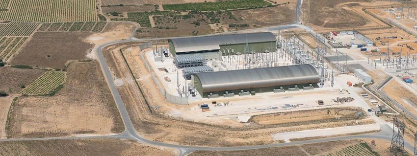
Independent study to examine the technical feasibility and cost of undergrounding the North-South Interconnector, April 2018

Executive Summary
A new North-South electricity interconnector has been proposed for development on the island of
Ireland in the form of a 138km 400kV single circuit overhead line (OHL) with the stated purpose of:
improving security of supply; removing the bottleneck between the transmission systems thus
facilitating the most efficient transfer of power across the island; and facilitating the integration of
renewable power sources onto the electricity system. The proposed development has been granted
planning approval by the relevant authorities in both the Republic of Ireland and Northern Ireland.

A number of studies have assessed alternatives to an OHL for North-South. The most recent was an
independent study by a Government-appointed ‘International Expert Commission’, conducted in the
second half of 2011 and published in early 2012. In that report, the Commission did not recommend
any solution as such. However, it recommended against fully undergrounding using an AC cable
solution. It noted that, if the option is to underground the connection along the whole, or main part of
the route, with the technology available at the time, the best solution would be a voltage source
converter (VSC) based high voltage direct current (HVDC) solution combined with cross-linked
polyethylene (XLPE) cables. It also stressed that an overhead line still offers significantly lower
investment costs than any underground alternative and could also be made more attractive by
investing slightly more in new tower designs rather than the classical steel lattice towers, at least for
part of the route.

Given the potential for changes in technology and cost since the publication of its previous study in
2012, the International Expert Commission has been re-convened to provide an update. This report
fulfils that purpose.

Recent developments in respect of the main technical options for the development of a new
interconnection between the Republic of Ireland and Northern Ireland are reported. In line with the
earlier report, these are:

     1.   an AC connection entirely made up of overhead line (OHL);
     2.   an AC connection comprising a combination of OHL and underground cable (UGC);
     3.   an undergrounded AC connection using a ‘gas insulated line’ (GIL);
     4.   a DC connection entirely made up of OHL;
     5.   a DC connection of which at least some of the connection uses underground cable, perhaps all of
          it underground.

The Commission’s 2012 report observed that option 1 – an AC connection entirely made up of OHL –
has generally been preferred by electricity network owners as it is significantly cheaper than the
alternatives. In addition, long sections of high voltage AC underground cable present major technical
problems and are generally avoided.

Since 2011, no major new technologies have emerged from the laboratory in a state of readiness for
commercial deployment. However, a number of examples of HVDC ‘embedded’ within an AC system
and avoiding the electrical problems associated with long high voltage AC underground cables are
either under development or have entered operation. Particular attention is therefore paid to
‘embedded’ HVDC.

A number of projects in Europe that make significant use of the main alternatives to conventional
overhead lines are described in order that these alternatives may be better understood. They include
three ‘embedded’ HVDC projects and two that are planned to use novel OHL tower designs.

                                                                                                                               2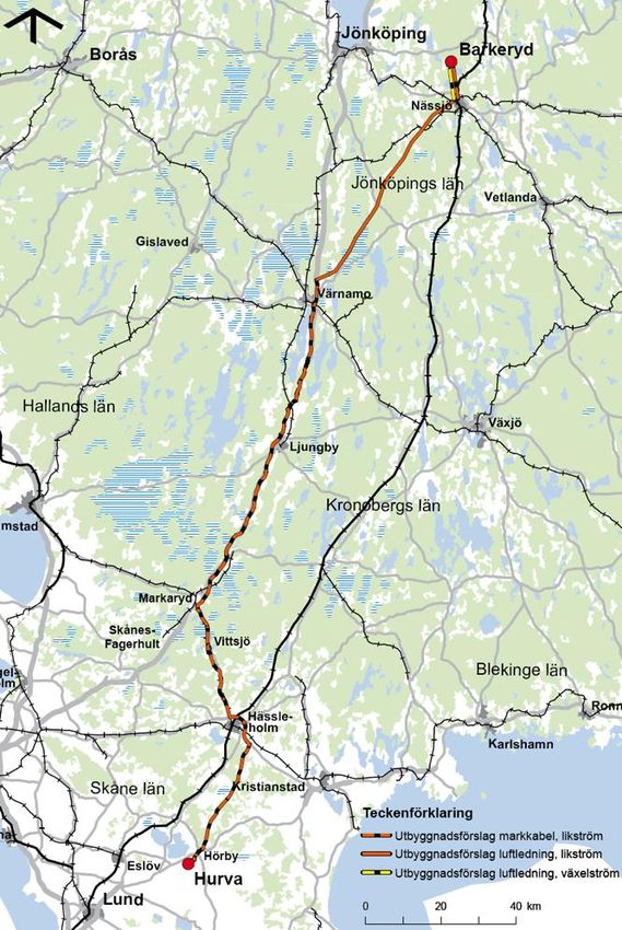
Independent study to examine the technical feasibility and cost of undergrounding the North-South Interconnector, April 2018

An update is presented of the Commission’s own, earlier estimate of the cost of developing North-
South as HVDC with underground cables as an alternative to an AC development with overhead line. It
can be concluded that the costs for both key alternatives, AC overhead line and HVDC underground
cables, have gone up. However, the cost relation is still the same: the HVDC option is more than three
times more expensive.

Then, as part of the Commission’s assessment of the feasibility of an alternative to overhead line
development for the new North-South interconnector, its context within the electricity system on the
island of Ireland is described.

The Commission’s new review of the technical options for enhancing the power transfer capability
between the Republic of Ireland and Northern Ireland has concluded that:

     •    Complete AC undergrounding is not viable; partial undergrounding is possible but with a limited
          total length of undergrounded sections.
     •    AC overhead line is viable; it would be possible to build the interconnection using new tower
          designs that are less visually intrusive but at an extra cost.
     •    A gas-insulated line (GIL) to cover the entire length would be extremely expensive and is, as yet,
          unproven anywhere in the world. Partial undergrounding using GIL would also be very
          expensive.
     •    The only viable means by which a high voltage interconnection of significant length could be
          completely undergrounded would be through use of an embedded HVDC link.

Embedded HVDC is not yet common worldwide but operational experience does exist and, within a few
years, there will be at least four examples in Europe of comparable size.

Although the Commission regards it as a credible option, there are a number of aspects of the potential
use of embedded HVDC in the context of enhancing the interconnection between Northern Ireland and
the Republic that would require careful consideration. Among these issues is that a number of parties
with which the Commission has consulted have expressed the need for economic development in the
areas through which the planned North-South interconnector passes. They have pointed specifically to
the possibility of attracting investment in new industrial or commercial facilities that have a need for
significant amounts of electrical energy, in particular data centres. However, development of a North-
South interconnector as embedded HVDC system would not achieve this.

Strictly limited partial undergrounding of an AC interconnection is possible but the Commission’s
understanding is that further planning enquiries would be necessary delaying commissioning of a new
interconnector by, we understand, at least two years with an annual constraint cost of, according to the
transmission system operator in Ireland, EirGrid, between 13 M€ and 20 M€ in the early years. Based
on current central estimates, adoption of an embedded HVDC alternative would delay commissioning
of a new interconnector by at least 5 years and would add approximately 120 M€ of additional
constraint costs to the extra cost of building the link as HVDC compared with the currently planned AC
OHL. The Commission’s own estimate of the extra capital cost of 1 × 1GW voltage source converter
(VSC) based embedded HVDC for a North-South interconnection compared with the planned 400kV AC
OHL is 270 M€ giving an estimated total extra cost of 390 M€ or, with 2 × 700MW, 570 M€.

The Commission’s overall finding is that, from a techno-economic point of view, an AC overhead line
is the most beneficial way of meeting the need for enhanced power transfer capability between the
Republic of Ireland and Northern Ireland.

                                                                                                                               3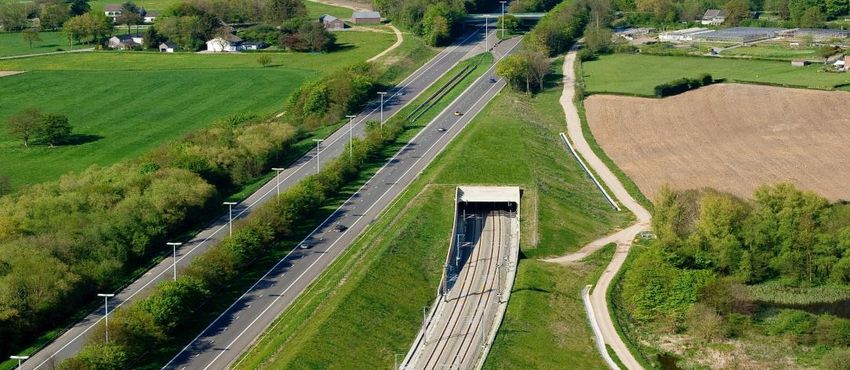
Independent study to examine the technical feasibility and cost of undergrounding the North-South Interconnector, April 2018

Contents
Executive Summary ..................................................................................................................................... 2
List of Tables ................................................................................................................................................ 5
List of Figures............................................................................................................................................... 5
1      Introduction ......................................................................................................................................... 7
     1.1       Background .................................................................................................................................. 7
     1.2       Commission membership and Terms of Reference for the review............................................. 7
     1.3       Outline of the report ................................................................................................................... 8
2      Main technical options ........................................................................................................................ 9
     2.1       Technology review: introduction ................................................................................................ 9
     2.2       Overhead line innovations since 2011 ...................................................................................... 10
     2.3       AC underground cable developments ....................................................................................... 11
     2.4       Gas-insulated lines (GIL) ............................................................................................................ 12
     2.5       HVDC systems: development of technology and market .......................................................... 13
     2.6       HVDC connections ‘embedded’ within an AC power system .................................................... 15
     2.7       Technology review: concluding remarks ................................................................................... 15
3      Illustrative projects ............................................................................................................................ 17
     3.1       Spain-France (INELFE) ................................................................................................................ 17
     3.2       Belgium-Germany (ALEGrO) ...................................................................................................... 20
     3.3       Norway-Sweden (South-West link) ........................................................................................... 24
     3.4       Great Britain (Western HVDC Link) ........................................................................................... 26
     3.5       Stevin project (Belgium) ............................................................................................................ 29
     3.6       Randstad project (The Netherlands) ......................................................................................... 33
     3.7       Hinkley Point C link (Great Britain) ............................................................................................ 33
4      HVDC with underground cable: estimated cost of development ..................................................... 35
5      System context of planned new North-South interconnector .......................................................... 37
     5.1       The situation today .................................................................................................................... 37
     5.2       Embedded HVDC as an option for tomorrow ........................................................................... 37
     5.3       Embedded HVDC on the island of Ireland ................................................................................. 39
6      Conclusions ........................................................................................................................................ 41
7      References ......................................................................................................................................... 44
A.     Electric and magnetic fields............................................................................................................... 47
     A.1       Basic physics .............................................................................................................................. 47
     A.2       Living nearby a high voltage line ............................................................................................... 48

                                                                                                                                                               4
Independent study to examine the technical feasibility and cost of undergrounding the North-South Interconnector, April 2018

       A.2.1           How do we notice electric fields?...................................................................................... 49
       A.2.2           How do we notice magnetic fields? .................................................................................. 49
    A.3        General health and electric and magnetic fields....................................................................... 50
    A.4        International standards and recommendations........................................................................ 51
       A.4.1           International Commission on Non-Ionizing Radiation Protection (ICNIRP) ...................... 51
       A.4.2           IARC − International Agency for Research on Cancer ....................................................... 51
       A.4.3           WHO World Health Organisation ...................................................................................... 52
       A.4.4           European standards – Council of Europe .......................................................................... 52
    A.5        Technical adaptations................................................................................................................ 52
    A.6        Conclusions ................................................................................................................................ 56
B      Meath–Tyrone International Expert Commission, Executive Summary, 2012 ................................. 57

List of Tables
Table 1: HVDC projects with cables awarded since 2011 (Source: Commission’s own review of
manufacturers’ press releases; costs are published Engineering, Procurement and Construction (EPC)
costs; total project costs are typically 20-30% larger than the EPC costs)................................................ 14
Table 2: New VSC HVDC projects in Europe with cables (Source: Commission’s own review of published
EPC costs). ................................................................................................................................................. 15
Table 3: 2011 estimates of the cost comparison between OHL and VSC HVDC with cables for North-
South [9] .................................................................................................................................................... 35
Table 4: 2011 estimates of costs of alternatives with reduced ratings [9] ............................................... 35
Table 5: Summary of published data on costs of recent HVDC projects. .................................................. 36
Table 6: Updated cost comparison between AC OHL and HVDC with underground cable ...................... 36
Table 7: Magnetic fields produced by domestic appliances ..................................................................... 50
Table 8: IARC cancer categories ................................................................................................................ 51

List of Figures
Figure 1: Typical shunt reactor for reactive power compensation [15] ................................................... 12
Figure 2: Accumulated awarded VSC HVDC Projects (Source: Commission’s own data). ........................ 13
Figure 3: Route of the INELFE interconnector [28] ................................................................................... 17
Figure 4: INELFE project: summary of routing and use of tunnel or trenches for underground cable [28]
................................................................................................................................................................... 18
Figure 5: INELFE project: cables in tunnel section [28] ............................................................................. 18
Figure 6: INELFE project: one of the converter stations [28] .................................................................... 19
Figure 7: The Belgian transmission network [30] ...................................................................................... 20
Figure 8: Major transmission projects in Belgium [31] ............................................................................. 21
Figure 9: Railway tunnel entrance in the Ardennes [29]........................................................................... 21
Figure 10: Connection of the ALEGrO project [29] .................................................................................... 22
Figure 11: ALEGrO project: cable sections [29] ......................................................................................... 22
Figure 12: ALEGrO project: cable routing [29] .......................................................................................... 23

                                                                                                                                                                    5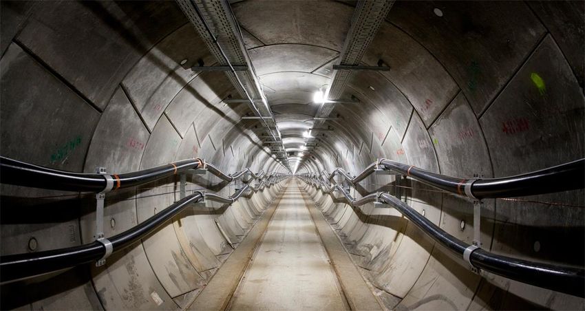
Independent study to examine the technical feasibility and cost of undergrounding the North-South Interconnector, April 2018

Figure 13: ALEGrO project: underground cable installation techniques [29] ........................................... 23
Figure 14: Illustrations of ALEGrO converter stations [29]....................................................................... 23
Figure 15: Main transmission boundaries in Sweden [32] ........................................................................ 24
Figure 16: Location of the South West Link [32] ....................................................................................... 24
Figure 17: Detail of the South West Link’s location [32] ........................................................................... 25
Figure 18: Location of the Western HVDC Link undersea cable [34] ........................................................ 26
Figure 19: Aerial view of the converter station under construction at Hunterston [35] .......................... 27
Figure 20: A section of underground cable under construction on the Western HVDC Link [36] ............ 27
Figure 21: Cable laying vessel for the Western HVDC Link [36] ................................................................ 28
Figure 22: The route of Stevin project [41] ............................................................................................... 30
Figure 23: Stevin project: routing of the AC underground cable showing section joints and installation
dates [41]................................................................................................................................................... 30
Figure 24: Stevin project: cross-section of cable trench [41] .................................................................... 30
Figure 25: Stevin project: illustration of cable access points [41] ............................................................. 31
Figure 26: Stevin project: illustration of underground cable access below ground [41] .......................... 31
Figure 27: Stevin project: Boudewijn Channel crossing [41] ..................................................................... 32
Figure 28: Stevin project: substation connecting overhead line and underground cable sections [41]... 32
Figure 29: ‘WinTrack’ towers used for overhead line sections [44] .......................................................... 33
Figure 30: National Grid’s 400kV T-pylon [48] .......................................................................................... 34
Figure 31: James Clerk Maxwell (left) and Michael Faraday (right) .......................................................... 48
Figure 32: The electromagnetic spectrum ................................................................................................ 48
Figure 33: General Arrangement of an IVI Tower proposed for use in the North-South interconnector [3]
................................................................................................................................................................... 53
Figure 34: Tower design used in the Stevin project [41] ........................................................................... 53
Figure 35: Compact tower design used in Sweden [9] .............................................................................. 54
Figure 36: Tower design used in the Randstad project [44] ..................................................................... 54
Figure 37: Section of a gas-insulated line (GIL) ......................................................................................... 55
Figure 38: Field strengths at different locations relative to an overhead line .......................................... 55
Figure 39: Magnetic field relative to the centre of an overhead line or underground cable ................... 56

                                                                                                                                                                    6
Independent study to examine the technical feasibility and cost of undergrounding the North-South Interconnector, April 2018

1 Introduction
1.1 Background
Currently there is one 275 kV double circuit (with a continuous Winter thermal rating of 2 × 881 MVA)
plus two 110 kV circuits connecting the transmission networks of the Republic of Ireland and Northern
Ireland. For operational reasons, the typical ‘secure’ level of power transfer between the two areas is
300 MW as a consequence of which they cannot operate as effectively as a single system thus limiting
the benefits that can be derived from the Single Electricity Market and the interconnection’s ability to
contribute to security of supply through access to additional generation capacity in either area [1].

A new 138 km long, 400 kV overhead line (OHL) with a Winter continuous thermal rating of 1500 MVA
[2] – the North-South Interconnector – has been proposed to enhance the connection between the
transmission networks of the Republic of Ireland and Northern Ireland.

According to EirGrid, the transmission system operator in the Republic of Ireland, the objectives of the
proposed North-South Interconnector development are [1]:

     •    improving security of supply;
     •    removing the bottleneck between the transmission systems thus facilitating the most efficient
          transfer of power across the island;
     •    facilitating the integration of renewable power sources onto the electricity system.

A “non-technical summary” of the proposed development can be found in [3]. From a system operation
perspective, the main outcome would be an increase in the secure power transfer capability between
the Republic of Ireland and Northern Ireland to, typically, between 1100 and 1300 MW [1].

The section of the proposed North-South Interconnector in the Republic of Ireland received planning
approval from An Bord Pleanála (ABP) on December 21st 2016 [4]. However, on February 16th 2017, a
Fianna Fáil private members’ motion on the interconnector “called on the Government to commission
an independent report to examine the feasibility and cost of putting the interconnector underground
and to ensure no further work is done on the interconnector until that analysis and a full community
consultation are completed” [5]. The motion was passed by 76 votes to 60.

On January 23rd 2018, the Department for Infrastructure in Northern Ireland approved planning
permission for the northern element of the North-South Interconnector following a positive
recommendation from the Planning Appeals Commission (PAC) [6].

A number of objections to the proposed development were submitted to the relevant planning
authorities. As noted in [7], a number of submissions to An Bord Pleanála urged the adoption of an
alternative to a new overhead line development, e.g. the undergrounding of any new line. The potential
for an underground alternative has been examined in a variety of studies, some independently-
commissioned and some commissioned by EirGrid. A number of these studies are summarised in [8].
The most recent independent study by a Government-appointed ‘International Expert Commission’ was
published in early 2012 [9].

Given the potential for changes in technology and cost since the publication of the independent study
published in 2012, it was proposed by the Irish Government that the International Expert Commission
be re-convened to provide an update on its earlier study, based on the terms of reference below.

1.2 Commission membership and Terms of Reference for the review
This report is prepared by the Commission composed of:

                                                                                                                               7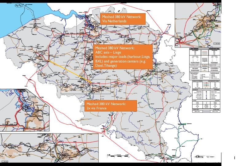
Independent study to examine the technical feasibility and cost of undergrounding the North-South Interconnector, April 2018

     •    Bo Normark, Chairperson Elimark AB, Sweden;
     •    Ronnie Belmans, 2BEnergy, Belgium;
     •    Keith Bell, University of Strathclyde, United Kingdom.

The Terms of Reference for the work were set by the Department of Communications, Climate Action
and Environment as follows.

     The Department of Communications, Climate Action and Environment requires an independent
     study to examine the technical feasibility and cost of undergrounding the North-South
     Interconnector, taking into account the most recent developments in technology and experience
     gained from existing projects abroad.

     The independent experts will:

     • review international literature, recent technology developments, international projects, and cost
       data in relation to overhead and underground high voltage power lines;
     • consult with the Minister, the Commission for Energy Regulation, EirGrid, the ESB, the North
       East Pylon Pressure Campaign, the County Monaghan Anti Pylon Committee and other bodies as
       deemed necessary;
     • examine the technical merits and construction and operation costs of the proposed project;
     • examine the technical feasibility and cost of an underground alternative to the North-South
       Interconnector which will include technical considerations in the context of the electricity
       networks of Ireland and Northern Ireland operating effectively as a single system thus increasing
       the benefits that are derived from the Single Electricity Market, and which will have regard,
       insofar as possible, to the potential underground route types (e.g. along roadway, cross-country,
       etc.) for the North-South Interconnector;
     • issue a final report within five months of commencing work that will include a comparison of the
       estimated construction and operation costs, and relative technical merits of the proposed
       overhead project and an underground alternative; and
     • present the results of the study to the Minister and the relevant Oireachtas Committee.

1.3 Outline of the report
The report is structured as follows. First, an update is provided on the main technical options for the
development of a new interconnection between the Republic of Ireland and Northern Ireland that were
reviewed in the earlier Commission report. Then, a number of projects that make significant use of the
main alternatives to conventional overhead lines are described in order that these alternatives may be
better understood. An update is presented of the Commission’s own, earlier estimate of the cost of
developing North-South as HVDC with underground cables as an alternative to an AC development with
overhead line. Then, as part of the Commission’s assessment of the feasibility of an alternative to
overhead line development for the new North-South interconnector, its context within the electricity
system on the island of Ireland is described. Finally, conclusions are presented.

Although consideration of issues and concerns associated with electric and magnetic fields is outside
the scope of the Commission, the Commission recognises the strong interest that stakeholders have in
such issues. An appendix to this report is therefore included that summarises electric and magnetic
field issues. For a fuller description and assessment, the interested reader is recommended to consult
two independent reports commissioned by the Irish Government [10][11] plus EirGrid’s submission to
ABP outlining its evaluation of alternatives to an OHL.

The Executive Summary from the Commission’s previous report is reproduced in a final appendix.

                                                                                                                               8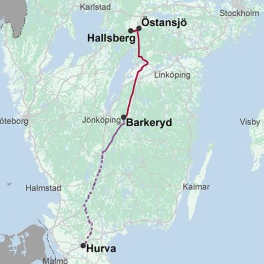
Independent study to examine the technical feasibility and cost of undergrounding the North-South Interconnector, April 2018

2 Main technical options
2.1 Technology review: introduction
The International Expert Commission’s report on the Meath-Tyrone interconnector published in 2012
reported the Commission’s judgement that there are 5 main alternative technologies that could be
used for the connection [9]:

          1.    an AC connection entirely made up of overhead line (OHL);
          2.    an AC connection comprising a combination of OHL and underground cable (UGC);
          3.    an undergrounded AC connection using a ‘gas insulated line’ (GIL);
          4.    a DC connection entirely made up of OHL;
          5.    a DC connection of which at least some of the connection uses underground cable, perhaps
                all of it underground.

No major new technologies have emerged from the laboratory in a state of readiness for commercial
deployment, except for a small first try out of high temperature superconductive cable in Essen
Germany taken into service in 2014 [12].

Ever since the late 1890s when Nikola Tesla’s ideas beat those of Thomas Edison in what became
known as the “war of the currents”, large, modern power systems all use alternating current (AC). The
main advantages are the ability to step voltages up and down and the ease of interrupting fault current.
High voltages allow power to be transmitted over long distances with low losses, but have significant
electrical insulation requirements. Power is therefore stepped down to lower voltages for distribution
to end users. However, since the 1960s, high voltage direct current (HVDC) has received growing
attention, initially for two reasons:

     •    to allow the interconnection of two AC power systems operating at different frequencies of
          oscillation of the alternating current; or
     •    to transmit over relatively long distances with reduced losses compared with AC.

HVDC has been enabled by the development of technology that allows conversion between AC and DC
and vice-versa at high voltages and powers. Innovation around HVDC has primarily concerned the use
of different devices, how they are connected together and how they are controlled. The converter
stations also represent both an advantage of HVDC and its main disadvantage. One benefit of HVDC is
its controllability. The power carried by an AC OHL or UGC depends on the locations of generators and
load on the network and the mesh of parallel routes between them. The power flowing on different
lines can only be modified by changing the amount of power being generated or used at particular
locations or by installing additional equipment such as phase shifting transformers. In contrast, under
normal conditions, the power carried on an HVDC OHL or UGC can be fully controlled. In this way, it can
reflect operator or electricity market preferences and can help the total capacity of parallel routes to be
optimally utilised. However, the big disadvantage is the extra cost – and physical footprint – of the
converter stations at each end of the route.

Along with other reports, the Commission’s 2012 report observed that option 1 – an AC connection
entirely made up of OHL – has generally been preferred by electricity network owners as it is
significantly cheaper than the alternatives. Although the conductors and insulators on an OHL are
exposed to the elements and therefore vulnerable to weather-related faults, e.g. due to lightning or in
high winds, physical damage resulting in long outage times is rare. Even then, the location of the fault
can be easily identified and a repair can normally be carried out quite quickly enabling the line to be
returned to service. In the past, once a route has been identified and relevant planning permissions

                                                                                                                               9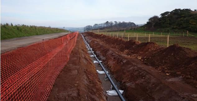
Independent study to examine the technical feasibility and cost of undergrounding the North-South Interconnector, April 2018

gained, the development timescales of OHL were generally moderate. However, in recent years and in
spite of the extra cost, objections to OHLs and delays in the granting of permissions have led to network
developers considering undergrounding, often for at least the most sensitive parts of an intended
route. Some grid companies use a compensation type of approach in which the construction of new
OHL at very high voltages is compensated by undergrounding nearby high voltage lines, e.g. in the
Stevin project described in Section 3.5. Another approach was discussed at the CIGRE Symposium in
Dublin 2017 concerning the first time that a section of OHL has been replaced for reasons of visual
amenity [13].

As will be recalled in section 2.3, long sections of high voltage AC underground cable present major
technical problems and are generally avoided. Thus, for distances beyond a few tens of km where an
OHL is not an option, e.g. undersea connections or where undergrounding is required, some other
technology is required. In 2012, the options were considered to be gas insulated lines (GIL) and HVDC.
Both avoid the problems associated with the high susceptance of insulated cables, the former because
a high pressure mix of, typically, 20% SF6 and 80% N2 gas is used to provide the electrical insulation, the
latter because of the use of direct current.

Since the previous report, no new commercially viable options have appeared representing alternatives
to those highlighted by the Commission in 2012. This chapter therefore concentrates on providing an
overview of recent developments of the same technologies with which the previous report was
concerned, based on reports that have emerged since 2011.

The rest of this chapter comprises the following:

     1.   an overview of OHL innovative approaches (built and design stage) since 2011;
     2.   an update on installations and issues associated with AC UGC;
     3.   an update on GIL;
     4.   an update on HVDC connections ‘embedded’ within an AC power system.

2.2 Overhead line innovations since 2011
The Commission’s report from 2012 described a number of innovations in respect of overhead lines. In
general, they are designed to

     1. make a more aesthetically pleasing tower;
     2. increase the power carried in a given corridor, through use of novel conductors with higher
        current capacity, through closer monitoring of the conductors relative to their limits or by
        reducing the width of the physical corridor required for an OHL construction to carry a given
        amount of power;
     3. reduce the number of towers required to carry the OHL;
     4. reduce the electro-magnetic field (EMF) associated with the line.

A number of new tower designs were highlighted in the 2012 report [9]. Many of these represented
compact designs that use composite materials to provide both electrical insulation and mechanical
strength thus avoiding the need for long cross-arms from which insulators and conductors are
suspended. The design of the towers of the Stevin project in Belgium is an application of these ideas as
discussed in section 3.5. TenneT’s WindTrack in the Netherlands also reduces the magnetic field and is
being used in the Randstad project for which a brief update is provided in section 3.6. They might also
be regarded as being ‘easier on the eye’ than conventional, steel lattice towers. However, they are
more expensive. A good example is the design used for future Hinkley Point C link described in section
3.7.

                                                                                                                               10
Independent study to examine the technical feasibility and cost of undergrounding the North-South Interconnector, April 2018
2.3 AC underground cable developments
AC underground cables (UGC) are widely used in urban environments within the lower voltage
distribution network. At such low voltages, the major problem with AC UGC is of negligible significance:
shunt susceptance. This represents the need for current into a piece of electrical equipment to be used
to charge it to a certain voltage before current can pass through the equipment. Similarly, the
equipment must be discharged for the current to reverse. In an AC system, this happens repeatedly
(every 10 ms at the 50 Hz frequency that is used in Europe). In the case of an overhead line (OHL) or
UGC, the charging and discharging must happen along the entirety of its length so that the required
charging current is larger for longer connections. The requirement also depends on the equipment’s
ability to store charge and this, in turn, is a function of the material used to provide electrical insulation.
For an OHL it is the air around the conductor; for a UGC it might take the form of specially designed
paper impregnated with oil (which must be suitably contained) or, in most new cables, cross-linked
polyethylene (XPLE). The susceptance of the materials used in cables is much higher than air. Moreover,
it is so high when the cable is operated at a high voltage that some additional equipment is often
required to compensate for the effect. In addition, special arrangements may be required to manage
the initial charging when a cable is switched in or discharging when it is switched out, either for routine
network rearrangement or because of a fault somewhere [14]. Switching of any item of equipment
electrically close to the cable can trigger interactions – resonances – between the cable and other
network elements to induce such high voltages that there is a significant risk of equipment being
permanently damaged and needing to be taken out of service for a long period of time while it is
replaced [14]. Furthermore, a long AC cable could amplify harmonics associated with the increasing use
of power electronics connected the system [14]. The high voltages associated with uncontrolled
resonances also represent a significant safety risk and the currents associated with harmonics can lead
to excessive heating of equipment.
The net result of the above is that power network operators are obliged to limit the total length of high
voltage UGC in their systems. A recent report by CIGRE Working Group B1.47 [15], reported that a 220
kV UGC commissioned in Australia in 2012 has a world record length of 88 km. It required the
installation of additional reactive compensation equipment and 235 joints to be made between
sections of cable. UGC does not eliminate electromagnetic field (EMF) issues. In this case, particular
arrangements of ducts were needed to minimise them. The Gemini offshore wind farm in the
Netherlands was connected in 2016 with around 110 km of 220 kV undersea cable. Higher voltage
underground or undersea cables do not reach such a length. The connection to Vancouver Island is
operated at 525 kV and has a total cable length of 39 km. The 245 kV connection between Sicily and
Malta has a total length of 119 km of AC cable [16].
All cases of high voltage cables of a few tens of km in length require special attention to the
susceptance effects. This often results in a need for blocks of shunt reactor compensation plus tuned
filters to deal with resonance issues and, perhaps, switched series resistors to limit charging currents
when the cable is being energised and ‘point on wave’ switching [14][17]. Although it usually suffices
with shorter cables to have shunt compensation at each end, longer cables may also require it part-way
along which means an additional above ground installation. All factors add extra cost. However, if the
key resonant frequency is close to 50 Hz, use of filters to manage the condition may be impractical. In
addition, the longest examples of AC UGC mentioned above – in Australia and for the Dutch offshore
wind farm – are radial connections that would normally be energised from the end connected to the
onshore, main interconnected system. Measures for the management of possible resonances and over-
voltages can be concentrated on that end. However, the proposed North-South development will be
embedded within the interconnected network and, thus, may be expected to be energised from either
end.
11Independent study to examine the technical feasibility and cost of undergrounding the North-South Interconnector, April 2018
Figure 1: Typical shunt reactor for reactive power compensation [15]
In contrast with OHL, UGC installations are largely protected from the environment and, thus, faults
may be expected to occur less often. However, because they are buried, locating where a repair needs
to be carried out can be difficult and the repair itself can be time-consuming with the result that overall
availability may be comparable with that of an OHL of similar length. Indeed, it is argued in [18] that
“long cable lengths impose a higher risk in transmission grids than overhead lines due to the failure rate
and repair time”. Typically, the part of a cable most vulnerable to failures is where sections are joined
together. Because long sections cannot be transported on land, many more separate sections are
required for underground cables than for a similar total length of undersea cables. As a consequence,
there are many more joints. However, pre-fabricated joints are now available making installation easier
and reducing the likelihood of faults. Most joints are put into well accessible joint pits.
Underground cables are typically buried in trenches although, on occasion, dedicated tunnels are dug,
e.g. one of 20 km in North London for a 400 kV AC cable. The width of the trench depends on the
number of individual cables and whether they are buried side-by-side or one above the other. (See, for
example, chapter 6 of the Commission’s 2012 report [9]). One option to reduce the susceptance
problem would be to use a lower voltage but, to have the same total power transfer capacity, a number
of parallel cables would be needed, increasing the cost and increasing the size of trench.
Detailed assessment of the system technical issues arising from use of long AC underground cables in
the context of the island of Ireland can be found in [19] and [20]. A further general summary of issues
associated with use of underground cables can be found in [21].
2.4 Gas-insulated lines (GIL)
A good description of the state of the art of Gas-Insulated-Lines can be found in [22].
Although the technology has major advantages, a real breakthrough for longer length remains to be
seen. Siemens is internationally recognized as the top provider of the technology [23].
12Independent study to examine the technical feasibility and cost of undergrounding the North-South Interconnector, April 2018
According to CIGRE Working Group B3/B1.09 [24], 250 km of GIL were in operation in 2008. This CIGRE
overview has not been updated since then.
2.5 HVDC systems: development of technology and market
Use of underground cables while avoiding the technical problems associated with long, high voltage AC
underground cables entails use of HVDC. This, in turn, requires converter stations at each end of the
cable-based connection. They are large and expensive but offer benefits in terms of control of power
flows.
The two main HVDC converter station options use ‘line commutated converter’ (LCC) or ‘voltage source
converter’ (VSC) technology. The latter has become increasingly popular in recent years and now
represents the majority of HVDC orders. Although the converter station has higher losses than an LCC
option, this is due to its extra controllability and the fact that it can operate on a weak network.
Between 2012 and 2017, over 2500 km of HVDC cable routes (705 km underground, 1840 km undersea)
were installed worldwide using VSC in 18 different projects [26]. Almost all of these made connections
between different synchronous areas.
The HVDC market has generally been strong in recent years. The development is following two parallel
trajectories.
1. Ultra high voltage DC (UHVDC) projects in Asia, mainly in China where a great expansion is
taking place with new projects using ever increasing line capacities. Several systems rated at
800 kV are in operation with capacities up to 8000 MW per line. The world’s largest system
stretching over 3400 km rated at 1100 kV and 12000 MW is under construction in China [25].
All these systems are built with classic LCC Technology.
2. Voltage Source Convertors (VSC) have become the norm for building smaller systems and are
almost always combined with at least some cable technology. The main market has been in
Europe.
Figure 2: Accumulated awarded VSC HVDC Projects (Source: Commission’s own data).
Since the Commission’s previous work in 2011 that was published in early 2012, the Commission has
identified that a total of 19 HVDC projects with cables have been awarded. Europe remains the
dominant market for HVDC cable projects. Some observations can be made.
13Independent study to examine the technical feasibility and cost of undergrounding the North-South Interconnector, April 2018
• All new HVDC projects with cables are based on the VSC technology.
• Almost all projects are interconnections or offshore wind connections.
• Two “embedded” links have been awarded since 2011: the ALEGrO project connecting Belgium
and Germany and a new project in India.
• Voltage level:
o 320 kV could be regarded as emerging as a “de facto” standard;
o 400 kV has been chosen for two projects;
o 500 kV is the highest VSC voltage in operation;
o two projects at 525 kV are under construction.
• Power level:
o 320 kV projects range between 600 MW and 1000 MW per convertor;
o the two 525 kV projects each have a 1400 MW rating.
• Power losses have been reduced from typically 1 % to typically 0.8 % per convertor. It does not
result in a significant change in the basic losses evaluation done in the Commission’s previous
report.
• Most cables are subsea cables but there are 6 projects with land cables.
• Total route length of subsea cables in the VSC schemes awarded since 2011 is 3169 km and of
land cables is 963 km.
• The dominant VSC suppliers are European: ABB, GE (former Alstom) and Siemens.
Cables are traditionally supplied by the European suppliers NKT (former ABB), Prysmian and Nexans.
Two new cable suppliers are now in the European market, J-Cable from Japan and Silec from France.
There is also a pipeline of new projects in Europe. Europe continues to be main market for HVDC cables
systems.
Table 1: HVDC projects with cables awarded since 2011 (Source: Commission’s own review of manufacturers’ press releases;
costs are published Engineering, Procurement and Construction (EPC) costs; total project costs are typically 20-30% larger than
the EPC costs)
Contract
Year Year in Value Voltage Distance Distance Distance MEuro/
order service Project Countries Application Meuro MW kV Total Sea Land MW
2011 2015 Skagerrak 4 Denmark/Norway SubSea 241 700 500 140 140 0 0,34
2011 2017 DolWin2 Holland Off-Shore 857 916 320 135 45 90 0,93
2011 2015 SylWin1 Holland Off-Shore 857 864 320 160 160 0 0,99
2011 2015 IFA 1 France - Spain Landcable 557 2000 320 65 0 65 0,28
2012 2015 ÅL-Link Åland Submarine 111 100 80 158 158 0 1,11
2012 2018 Sydvästlänken Sweden Underground + OH 394 1200 320 190 0 190 0,33
2013 2017 Dolwin 3 Germany Offshore + Land 866 900 320 162 83 79 0,96
2014 2017 Maritime Link Canada SubSea 343 500 200 360 360 0 0,68
2014 2018 Caithness Moray Scotland Subsea 484 800 320 160 160 0 0,60
2015 2021 NSN Norway - UK Subsea 1257 1400 525 740 740 0 0,90
2015 2020 Nordlink Norway - Germany SubSea 1200 1400 525 623 623 0 0,85
2015 2019 NEMO Belgium - UK Subsea 496 1000 400 140 130 10 0,49
2015 2019 Frejus France - Italy Landcable 1397 910 320 190 0 190 1,53
2016 2019 Cobra Denmark - Holland Subsea 411 480 320 325 325 0 0,85
2016 2019 Alegro Belgium - Germany Landcable 399 1000 320 90 0 90 0,40
2017 2023 Dolwin 6 Germany Offshore + Land 1028 900 320 90 45 45 1,14
2017 2020 ElecLink France - UK Land 437 1000 320 51 0 51 0,44
2017 2020 IFA 2 France - UK Subsea + Land 621 1000 400 225 200 25 0,62
2017 2020 India VSC India Land 446 1000 320 200 0 128 0,44
12403 18070 4204 3169 963 0,00
14Independent study to examine the technical feasibility and cost of undergrounding the North-South Interconnector, April 2018
Table 2: New VSC HVDC projects in Europe with cables (Source: Commission’s own review of published EPC costs).
Contract
Year Year in Value Voltage Distance Distance Distance
order service Project Countries Application Meuro MW kV Total Sea Land
2018 2021 Shetland UK Subsea + Land 343 600 300 267 257 10
2018 2021 FAB Link France - UK Subsea + Land 848 1400 320 216 171 45
2018 2021 Western Isles UK Subsea + Land 0 450 320 156 80 76
2018 2022 NorthConnect UK - Norway Subsea 0 1400 525 655 655 0
2018 2022 Viking Link UK - Denmark Subsea + Land 0 1400 400 770 630 140
2020 2024 Eastern Link UK Subsea 0 2000 400 305 305 0
7250 2369 2098 271
2.6 HVDC connections ‘embedded’ within an AC power system
An HVDC option for making a new interconnection between Northern Ireland and the Republic of
Ireland would operate in parallel with AC circuits and be ‘embedded’ within a single synchronous area.
There are 17 examples of embedded HVDC in operation globally of which 11 are in China [26]. One was
recently commissioned in Europe between France and Spain – INELFE – and is discussed in section 3.1.
Five others are under development in Europe. They include the ALEGrO project between Belgium and
Germany discussed (section 3.2) and the South-West Link between Norway and Sweden (section 3.3). In
addition, the Western HVDC Link in Britain discussed (section 3.4) is expected to be commissioned in
2018.
The main limiting factor regarding use of HVDC with cables is the rating that can be achieved for the
cable. INELFE uses 320kV cables. In order to give the required power transfer capability, INELFE
comprises two parallel 1 GW connections. However, the NEMO interconnector between Belgium and
Britain using VSC HVDC and undersea cables planned for commissioning in 2019 will operate at 400 kV
and Nordlink between Germany and Norway and NSN between Norway and Britain will each be
commissioned in 2021 and operate at 525 kV with a power capacity of 1400 MW. Importantly, the use
of HVDC underground cables does involve some – though not all – of the issues associated with AC
UGC, in particular the high number of joints and the relatively long repair times in the event of faults.
(Section 2.3).
Another potential issue with use of HVDC is that a future wish to extend the DC side to, for example, a
third terminal would involve multi-terminal operation for which there is little operational experience,
the only VSC examples to date being two projects in China, Nan’ao Island and Zhoushan.
The Commission is not aware of any particular operational difficulties that have emerged from the
embedded HVDC systems already in operation. However, the system operators on the island of Ireland
have no experience with such systems.
2.7 Technology review: concluding remarks
The Commission’s understanding is that the main objections to the planned and, now, approved
development of a new North-South interconnector concern (i) visual impact and (ii) concerns about
electro-magnetic fields (EMF). As was noted in section 1, EMF issues are outside the scope of the
Commission’s Terms of Reference.
In common with the Commission’s previous findings published in early 2012, the technology review
presented above reveals that the main alternatives to AC OHL development for North-South that
promise to reduce the visual impact of the development are:
1. use of underground cables for some or all of the route;
15Independent study to examine the technical feasibility and cost of undergrounding the North-South Interconnector, April 2018
2. use of a novel design of tower for overhead lines that reduces the size of the corridor or
improves the appearance of the line.
In respect of 1, the review of the use of AC underground cable suggests that it is not a viable option
except, perhaps, for a very limited length, e.g. no more 10km. If the entire length of the connection is to
be undergrounded, the problems caused by the susceptance of an AC cable suggest that it should be
built to carry direct current (DC) at a high voltage. This would entail the development being one of an
‘embedded’ HVDC system. The significant development in recent years of the market for HVDC using
undersea or underground cables and the commissioning or construction of a number of ‘embedded’
HVDC links suggests that this option is commercially viable.
For the purposes of illustration, the next chapter reports on some developments of ‘embedded’ HVDC
in Europe. It also reports on one example of a new design of tower being used to improve the
appearance of an OHL.
16Independent study to examine the technical feasibility and cost of undergrounding the North-South Interconnector, April 2018
3 Illustrative projects
The previous chapter presented an update of the Commission’s previous review of the main technology
options that might be considered as alternatives to an AC OHL development. It concluded that the
main, commercially viable means by which the route might be entirely undergrounded would be by
means of ‘embedded’ HVDC link. It also noted that the appearance of an OHL route might be improved
by use of a novel tower design.
This chapter presents short, illustrative summaries of four ‘embedded’ HVDC projects that are either
operational or under development in Europe. It also briefly reports on two AC projects in Europe –
Stevin and Randstad – that use short sections of AC underground cable. Both also use a novel design of
tower for the overhead line section. Finally, proposals in Great Britain to use a novel tower design for a
section of new 400 kV overhead line are described along with the British regulator’s published opinion
of the cost of such a tower.
3.1 Spain-France (INELFE)
Until the installation of the new HVDC link, the Electrical interconnection between Spain and France
consisted of four lines, the last of which was built in 1982: Arkale-Argia, Hernani-Argia, Biescas-
Pragneres y Vic-Baixas. They have a total commercial exchange capacity of 1400 MW, meaning that
they represent only 3% of the current maximum demand in the Iberian Peninsula [27]. It made the
Iberian Peninsula to have one of the lowest interconnection ratios in the European Union, thereby
limiting the possibilities of helping or receiving assistance in the event that there is a failure in any of
the electrical systems. This new interconnection line doubles the level of interconnection between
France and Spain from its current 3% to 6%, i.e. it will add on another 1400 MW to reach 2800 MW, still
below the 10% recommended by the European Union.
The owners of all interconnections are and will be Red Eléctrica de España and Réseau de Transport
d'Electricité (RTE). For this specific new project, a special purpose company has been established, being
INELFE (Interconnection Electrical France-Espagna, https://www.inelfe.eu/en ), a joint venture company
between RED and RTE, governed by French law. After the first project as discussed here, the company
will build the connection Gatika (near Bilbao, Spain) to Cubnezais (near Bordeaux, France) via the Bay of
Biscay.
Figure 3: Route of the INELFE interconnector [28]
The agreement was signed in 2008 in Zaragoza. As a final step in permitting, RED Electrica obtained the
Environmental Impact Declaration (EID) of the project on December 13, 2010. In 2014, the works were
completed: converter stations, tunnel and underground connections. In 2015 the systems were
17Independent study to examine the technical feasibility and cost of undergrounding the North-South Interconnector, April 2018
activated, tested and integrated. Late 2015 the commercial operations on the Baxias-Santa Llogaia line
were started.
The overall length of the connection is 64.5 km, 33.5 km in France and 31 km in Spain [28]. The central
part of the line crosses the Pyrenees at the Albera massif (Figure 3). An 8.5 km tunnel was built for this
section: 1 km in Spain and 7.5 km in France. The rest of the line is buried in a trench.
On the Spanish side, the line crosses the Empordà through the municipalities of Santa Llogaia, Vilafant,
Figueres, Llers, Pont de Molins, Cabanes, Biure, Capmany, Darnius, Agullana, and La Jonquera. For the
most part, the layout is parallel to the AP-7 motorway and the high-speed railway.
The layout on the French side was the result of 15 months of consultations with representatives and
associations from the region. The line passes through the towns of Baixas, Baho, Villeneuve-la-Rivière,
Le Soler, Toulouges, Canohès, Ponteilla, Trouillas, Villemolaque, Banyuls dels Aspres, Tresserre, and
follows the high-speed railway for most of its layout up to the tunnel entrance, in Montesquieu des
Albères (Figure 4). The tunnel then goes under the municipalities of Le Boulou, Les Cluses, and Le
Perthus (Figure 5).
Figure 4: INELFE project: summary of routing and use of tunnel or trenches for underground cable [28]
Figure 5: INELFE project: cables in tunnel section [28]
Siemens’ “HVDC Plus” technology is used, based on self-commutated voltage-sourced converters (VSC)
in a modular multilevel converter configuration (MMC) that converts alternating current (AC) into direct
current and direct current, VSC works with IGBT power transistors that can be switched off enabling the
18You can also read