Performance Rating of Centrifugal Refrigerant Compressors - 2022 Standard for AHRI Standard 1520-2022 (SI/I-P)
←
→
Page content transcription
If your browser does not render page correctly, please read the page content below

AHRI Standard 1520-2022 (SI/I-P)

2022 Standard for
Performance Rating of
Centrifugal Refrigerant
Compressors
IMPORTANT
 SAFETY DISCLAIMER
 AHRI does not set safety standards and does not certify or guarantee the safety of any products,
 components or systems designed, tested, rated, installed or operated in accordance with this
 standard/guideline. It is strongly recommended that products be designed, constructed,
 assembled, installed and operated in accordance with nationally recognized safety standards
 and code requirements appropriate for products covered by this standard/guideline.

 AHRI uses its best efforts to develop standards/guidelines employing state-of-the-art and
 accepted industry practices. AHRI does not certify or guarantee that any tests conducted under
 its standards/guidelines will be non-hazardous or free from risk.

 Note:

 This is a new Standard

 AHRI Certification Program Disclaimer
AHRI Standards are developed independently of AHRI Certification activities and may have scopes that include
products that are not part of the AHRI Certification Program. The scope of the applicable AHRI Certification
Program can be found on AHRI’s website at www.ahrinet.org.

Price $10.00 (M) $20.00 (NM) ©Copyright 2022, by Air-Conditioning, Heating, and Refrigeration Institute
Printed in U.S.A. Registered United States Patent and Trademark Office

TABLE OF CONTENTS

SECTION PAGE

Section 1. Purpose................................................................................................................................ 1

Section 2. Scope................................................................................................................................... 1

Section 3. Definitions .......................................................................................................................... 1

Section 4. Test Requirements .............................................................................................................. 3

Section 5. Rating Requirements........................................................................................................... 4

Section 6. Minimum Data Requirements for Published Ratings ......................................................... 9

Section 7. Operating Requirements ................................................................................................... 10

Section 8. Marking and Nameplate Data ........................................................................................... 11

Section 9. Conformance Conditions .................................................................................................. 11

 TABLES
Table 1. Rating Methods ................................................................................................................... 5

Table 2. Application Envelope (I-P) ................................................................................................. 6

Table 3. Application Envelope (SI) .................................................................................................. 6

Table 4. Rating Uncertainty Limits................................................................................................... 6

Table 5. Reference Rating Conditions (I-P)...................................................................................... 8

Table 6. Reference Rating Conditions (SI) ....................................................................................... 9

Table 7. Published Ratings ............................................................................................................. 10

 FIGURES
Figure 1. Rating Uncertainty Limits................................................................................................... 7

Figure 2. Application Envelope with Reference Rating Conditions Shown (I-P).............................. 7

Figure 3. Application Envelope with Reference Rating Conditions Shown (SI) ............................... 8
APPENDICES
Appendix A. References - Normative .................................................................................................... 12

Appendix B. References - Informative................................................................................................... 13

Appendix C. Verification of Published Ratings for a Population of Compressors - Informative .......... 14

Appendix D. Derivation of Reference Rating Conditions - Informative................................................ 16

Appendix E. Methods for Calculating Centrifugal Compressors Performance – Informative .............. 17

 TABLES FOR APPENDICES
Table C1. Rating Uncertainty Limits Using a Sample Size of 3 ....................................................... 14

Table D1 Sample Compressor Rating Conditions based on AHRI 550/590 Standard Water-Cooled
 Chiller Rating Conditions ................................................................................................. 16

Table D2 Sample Compressor Rating Conditions based on AHRI 550/590 Standard Air-Cooled
 Chiller Rating Conditions ................................................................................................. 16

Table E1 Two Stage Performance Parameters Segmented by IGV ................................................. 19

 FIGURES FOR APPENDICES
Figure E1. Cycle schematic and pressure-enthalpy diagram for a two-stage compressor with Vapor
 Injection using a flash tank economizer............................................................................ 17
_________________________________________________________ AHRI STANDARD 1520-2022 (SI/I-P)

 PERFORMANCE RATING OF
 CENTRIFUGAL REFRIGERANT COMPRESSORS
 Section 1. Purpose

1.1 Purpose. The purpose of this standard is to establish for Centrifugal Compressors: definitions, test requirements,
rating requirements, minimum data requirements for Published Ratings, operating requirements, marking and nameplate data,
and conformance conditions.

 1.1.1 Intent. This standard is intended for the guidance of the industry, including manufacturers, engineers,
 installers, contractors and users. The standard defines the minimum amount of information, in a standard form to
 enable the evaluation and comparison of different Centrifugal Compressors for use in an application.

 1.1.2 Review and Amendment. This standard is subject to review and amendment as technology advances.

 Section 2. Scope

2.1 Scope. This standard applies to Centrifugal Compressors and their presentation of performance in heating, ventilation,
and air-conditioning applications. The manufacturer is solely responsible for the determination of values to be used in published
product information. This standard stipulates the minimum amount of information to be provided and suggests a method to be
used to verify the accuracy of that information.

2.2 Exclusions.
 2.2.1 This standard does not apply to compressors intended for use in:
 a. Household refrigerators and freezers
 b. Automotive air-conditioners
 c. Household dehumidifiers
 d. Industrial products other than heating and cooling
 e. Compressed air applications

 2.2.2 This standard does not apply to compressors when contained within a package or system.

 Section 3. Definitions

All terms in this document will follow the standard industry definitions in the ASHRAE Terminology website unless otherwise
defined in this section.

3.1 Flow. Volumetric flow rate through the compressor expressed in ft 3/min, m3/sec.

3.2 Individual Published Rating. A data table used to represent the nominal performance of a Compressor at a single
Step.

3.3 Interstage Port. An inlet port for vapor or liquid between two stages of compression.

3.4 Model Number. The identifier for a product containing one or more Compressors and any accessories that are supplied
by the manufacturer, required to sustain operation of the Compressor(s) at the rating conditions or that impact the Published
Rating.

Note: Accessories may include, but are not limited to, interconnecting piping, fans, liquid receivers, desuperheaters, strainers,
service valves, check valves, suction filters, lubricant separators, motors, motor starters, and unloaders, as supplied or specified
by the compressor manufacturer.

 3.4.1 Centrifugal Compressor. A dynamic compression machine in which an increase in refrigerant vapor
 pressure is attained by imparting velocity to the refrigerant and then increasing static pressure by a reduction in the
 1
_________________________________________________________ AHRI STANDARD 1520-2022 (SI/I-P)

 velocity through work applied to the compressor’s mechanism. For clarity of this standard, the term Compressor
 implies Centrifugal Compressor.

 3.4.2 Compressor Housing Types

 3.4.2.1 Hermetic Refrigerant Compressor. A Compressor and motor assembly, both of which are contained
 within a gas tight housing that is permanently sealed by welding or brazing with no access for servicing
 internal parts in the field.

 3.4.2.2 Open Type Refrigerant Compressor. A Compressor with a shaft or other moving part extending
 through its casing to be driven by an outside source of power thus requiring a shaft seal or equivalent rubbing
 contact between fixed and moving parts.

 3.4.2.3 Semi-hermetic Refrigerant Compressor. A Compressor and motor assembly contained within a gas-
 tight housing that is sealed by gasketed joints to provide access for servicing internal parts.

3.5 Population of Compressors. Compressors intended to perform the same function, produced in quantity, manufactured
to the same technical specifications and characterized by the same Published Rating.

3.6 Power Input. The time rate of energy usage of the Compressor (compressor power) plus any accessories required to
sustain operation of the compressor at the Rating Condition.

3.7 Published Operating Range. The applicable boundaries of head and flow coefficients for which ratings are
published.

3.8 Published Rating. Composed of Individual Published Ratings used to represent the nominal performance of a
Compressor.

 3.8.1 Individual Published Rating. A data table used to represent the nominal performance of a Compressor at a
 single Step.

3.9 Rating Condition. A saturated suction temperature and saturated discharge temperature point used to determine the
number of Steps required to be published per Section 5.

3.10 Rating Uncertainty Limit (Tolerance). The limit within which the measured performance of an individual
Compressor falls relative to the Published Rating.

3.11 Reference Rating Conditions. A specific operating condition selected from Table 4 for quick reference or
comparison.

3.12 Refrigerant Mass Flow Rate. The mass flow rate of the volatile refrigerant, which is potentially mixed with
lubricant.

3.13 Refrigerating Capacity. The capacity associated with the increase in total enthalpy between the refrigerant
entering the evaporator and the superheated return gas entering the Compressor. The calculation of Refrigeration Capacity
does not include parasitic heat transfer effects., expressed in Btu/h, W.

Terms used to determine the number of Steps required to be published per Section 5:

 3.13.1 Maximum Capacity. The rated Refrigerating Capacity of the modulating Compressor operating at the
 Maximum Step for a manufacturer defined Rating Condition, expressed in Btu/h, W.

 3.13.2 Minimum Capacity. The rated Refrigerating Capacity of the modulating Compressor operating at the
 Minimum Step for a manufacturer defined Rating Condition, expressed in Btu/h, W.

 3.13.3 % Capacity. A percentage of the Maximum Capacity based on the manufacturer defined Rating Condition
 2
_________________________________________________________ AHRI STANDARD 1520-2022 (SI/I-P)

 at a specific Step (Maximum Capacity is 100% Capacity).

3.14 Step. A level of modulation achieved by changing the Flow not limited to the examples listed below:

 3.14.1 Step Method

 a. VFD frequency, Hz
 b. Compressor speed, RPM
 c. Mechanical unloading setting (fixed or time weighted average) (%).

 Note: This “%” is a representation or name of the Step and not necessarily an actual % Capacity.

 3.14.2 Maximum Step. The Step producing the highest Flow of the modulating Compressor.

 3.14.3 Minimum Step. The Step producing the lowest Flow of the modulating Compressor.

3.15 "Shall" or "Should," shall be interpreted as follows:

 3.15.1 Shall. Where "shall" or "shall not" is used for a provision specified, that provision is mandatory if compliance
 with the standard is claimed.

 3.15.2 Should. "Should" is used to indicate provisions which are not mandatory, but which are desirable as good
 practice.

3.16 Vapor Injection. A method of increasing evaporator capacity using an economizer to sub-cool liquid refrigerant
exiting the condenser and reducing discharge temperature. Refrigerant vapor or wet vapor that exits the economizer enters an
intermediate port or an interstage port on the compressor.

3.17 Variable Frequency Drive (VFD). A power electronic device that regulates the speed of an alternating current (AC)
motor by adjusting the frequency and the voltage of the electrical power supplied to the motor.

 Section 4. Test Requirements

4.1 Test Requirements. All Published Ratings shall be verified by tests conducted in accordance with ANSI/ASHRAE
Standard 225.

4.2 Ambient Temperature. Published Ratings shall be established with an ambient temperature around the Compressor
and its accessories of 95.0°F, 35.0°C. If Published Ratings are established at ambient temperatures other than 95.0°F, 35.0°C,
the actual ambient temperature used to establish the Published Ratings shall be stated by the manufacturer.

4.3 Airflow. Published Ratings shall be established with no airflow across the Compressor. If Published Ratings
are established with airflow across the compressor, the details of the airflow over the Compressor used to establish
Published Ratings shall be stated by the manufacturer.

4.4 Nameplate Voltages for Rating. Published Ratings shall be established using the nameplate rated voltage
and frequency. For dual nameplate voltage ratings, Published Ratings shall be established using both voltages, or
using the higher of the two voltages, if only a single rating is to be published.

4.5 Power Input. For Hermetic or Semi-hermetic Refrigerant Compressors with a factory integrated or factory specified
VFD, the Power Input is measured at the VFD input terminals. If accessories are not included, it shall be explicitly stated.

 3
_________________________________________________________ AHRI STANDARD 1520-2022 (SI/I-P)

 Section 5. Rating Requirements

5.1 Published Rating. A Published Rating is one or more Individual Published Ratings that represents Flow coefficient,
head coefficient, and isentropic efficiency parameters across the Published Operating Range of the Compressor.

 5.1.1 Reference Rating Condition. Superheat, Subcooling, Saturation Temperatures, and/or return gas temperature
 conditions specified in Table 4 shall be used for reference rating conditions. The intent of the reference rating conditions
 is for manufacturers to publish performance for the ease of comparing to other compressors.

 5.1.2 Continuous Modulating Compressor. The Published Rating of a continuous modulating Compressor shall be
 provided per the following requirements to comprise each set of Individual Published Ratings.

 5.1.2.1 An Individual Published Rating of the Compressor at the Maximum Rated Step.

 5.1.2.2 An Individual Published Rating of the Compressor at the Minimum Rated Step.

 5.1.2.3 At least two Individual Published Ratings of the Compressor between the Maximum and Minimum
 Rated Step.

 5.1.2.3.1 Each Step shall be evenly spaced between the Maximum and Minimum Rated Step within
 ± 5%.

 5.1.2.4 An individual published rating of the Compressor shall contain sufficient points such that
 interpolation between the points produces a representation within the specified uncertainty found in Table 4
 and Figure 1.

 5.1.3 Operating map.

 5.1.3.1 Surge definition. The lowest flow point along an Individual Published Rating will be considered
 the last stable operating point prior to surge at that step.

 5.1.3.2 Choke definition. The highest flow point along an Individual Published Rating will be considered
 the choke point.
5.5 Rating Methods. Compressors or compressor units shall be rated in one of four ways shown in Table 1. Manufacturers
shall declare which rating method is used when providing Published Ratings. If no method is referenced it is assumed that
AHRI Standard 1520 Method 1 is used.

 4
_________________________________________________________ AHRI STANDARD 1520-2022 (SI/I-P)

 Table 1. Rating Methods1,
 Liquid Liquid
 Vapor Exiting
 Method Economizer Leaving Exiting
 Economizer
 Condenser Economizer
 1 None N/A N/A N/A
 Manufacturer
 Specified Stated by
 2 Note 2 Note 3
 Heat manufacturer
 Exchanger
 Non-
 Specified
 3 Note 2 Note 3 Note 4
 Heat
 Exchanger
 4 Flash Tank Note 2 Note 3 Note 5
 Notes:
 1. For all methods, other than mechanical sub-cooling in the
 economizer, there is no parasitic heat gain or loss in the liquid line.
 2. Liquid temperature leaving the condenser shall be assumed to have 0
 ºR, 0 K subcooling unless otherwise stated by the manufacturer.
 3. Manufacturer shall specify the outlet liquid temperature of the
 Economizer or the approach temperature.
 4. Vapor temperature leaving the economizer shall be 9 ºR, 5 K above
 the dew point temperature corresponding to the pressure at the
 Intermediate or Interstage Port of the compressor.
 5. Vapor temperature leaving the economizer shall be equal to the dew
 point temperature corresponding to the pressure at the Intermediate or
 Interstage Port of the compressor.

5.6 Rating Uncertainty Limits of Published Ratings. To comply with this standard, single sample product verification
test results, conducted at conditions within the Application Envelope defined in Table 2. and Table 3, shall meet the
Published Ratings of the Compressor within the Rating Uncertainty Limits defined in Table 4, unless uncertainty is specified
differently by the manufacturer for each rating point.

 5
_________________________________________________________ AHRI STANDARD 1520-2022 (SI/I-P)

 Table 2. Application Envelope (I-P)
 Rating Conditions Region 1 Region 2 Region 3
 Suction Dew Point, °F ≥-40 and
_________________________________________________________ AHRI STANDARD 1520-2022 (SI/I-P)

 120.0%
 Power Input
 115.0%

 110.0%

 Uncertainty Limits 105.0%
 Refrigerating Capacity,
 100.0% Refrigerant Mass Flow Rate,
 EER, and COP
 95.0%

 90.0%

 85.0%

 80.0%
 0% 20% 40% 60% 80% 100%
 % Capacity

 Region 1 Region 2 Region 3

 Figure 1. Rating Uncertainty Limits

Figure 2, Figure 3, are graphical representations of the Application Envelopes shown in Table 2 and Table 3.

 Figure 2. Application Envelope
 with Reference Rating Conditions Shown (I-P)

 7
_________________________________________________________ AHRI STANDARD 1520-2022 (SI/I-P)

 Figure 3. Application Envelope
 with Reference Rating Conditions Shown (SI)

5.7 Reference Rating Conditions. The manufacturer shall identify the operating condition when publishing single point
rating information. Reference rating conditions are shown in Table 5 and Table 6.

 Table 5. Reference Rating Conditions (I-P)2
 % Capacity
 Temperature Points
 100 75 50 25
 Suction Dew Point, °F 43 43 43 43
 Discharge Dew Point (air-cooled), °F 124 102 82 66
 Discharge Dew Point (water-cooled), °F 97 84 72 68
 Suction Return Gas Temperature, °F 63 63 63 63
 or
 Superheat1, R 20 20 20 20
 SubcoolinE3, R 0 0 0 0
 Notes:
 1) The manufacturer shall clearly state which superheat is published.
 2) Refer to Figure 2 graphical representation of the Reference Rating Conditions.
 3) Refer to Appendix C for subcooling calculation for capacity.

 8
_________________________________________________________ AHRI STANDARD 1520-2022 (SI/I-P)

 Table 6. Reference Rating Conditions (SI)2
 % Capacity
 Temperature Points
 100 75 50 25
 Suction Dew Point, °C 6 6 6 6
 Discharge Dew Point (air-cooled), °C 51 39 28 19
 Discharge Dew Point (water-cooled), °C 36 29 22 20
 Suction Return Gas Temperature, °C 17 17 17 17
 or
 Superheat1, K 11 11 11 11
 SubcoolinE3, K 0 0 0 0
 Notes:
 1) The manufacturer shall clearly state which superheat is published.
 2) Refer to Figure 3 graphical representation of the Reference Rating Conditions.
 3) Refer to Appendix C for subcooling calculation for capacity.

 Section 6. Minimum Data Requirements for Published Ratings

6.1 Minimum Data Requirements for Published Ratings. Table 7 provides minimum data requirements for published
ratings. At a minimum a data point at the 100% Reference Rating Condition shall be published. Any exceptions to the ambient
temperature and airflow per Section 4.2 and 4.3 shall be stated.

 9
_________________________________________________________ AHRI STANDARD 1520-2022 (SI/I-P)

 Table 7. Published Ratings
 Published Values Units
 General
 Model Number -
 Refrigerant Designation per ANSI/ASHRAE Standard 34 -
 Voltage V
 Phase -
 Frequency Hz
 Rating Method -
 Performance Data
 Overall Compressor Efficiency1, 2, 3, 4 -
 Refrigerant flow coefficient (suction) of each Stage -
 Head coefficient of each Stage -
 Refrigerating Capacity at 100% reference point
 Power at 100% reference point
 Additional Information
 Step Hz, RPM, %, Hz
 VFD frequency,
 Compressor speed,
 Step Method Mechanical unloading
 (IGV and/or diffuser
 setting)
 Notes:
 1. If a compressor package includes a motor and/or VFD, the motor and/or VFD
 shall be included as part of the published efficiency rating.
 2. Motor and/or VFD part number shall be published if motor and/or VFD efficiency
 is included in ratings and the motor and/or VFD is not shipped with the
 Compressor.
 3. In the case of open drive compressors, efficiency will be relative to shaft input
 power.
 4. If Published Ratings include the efficiency of the motor and/or VFD and are
 established with additional cooling means, or an ambient temperature other than
 defined in Section 4, the details of the cooling fluid, fluid flow rate and entering
 fluid temperature cooling the motor and/or VFD shall be stated by the
 manufacturer.

6.2 Claims to Ratings. All claims to ratings within the scope of this standard shall include the statement “Rated in
accordance with AHRI Standard 1520”. All claims to ratings outside the scope of this standard shall include the
statement “Outside the scope of AHRI Standard 1520”. Wherever ratings are published or printed, they shall include
a statement of the conditions at which the ratings apply. If no Rating Method is explicitly identified, Rating Method 1 is
assumed.

 Section 7. Operating Requirements

7.1 Loading Requirements. The Compressor shall be capable of operating continuously at all operating points in the Published
Operating Range for a minimum period of two hours at the minimum and maximum utilization voltage as described in
ANSI/AHRI Standard 110, Table 1. There is no expectation that the Compressor will meet the Published Rating at the
maximum or minimum utilization voltage.

 10
_________________________________________________________ AHRI STANDARD 1520-2022 (SI/I-P)

 Section 8. Marking and Nameplate Data

8.1 Compressor Nameplate Marking. As a minimum, each Compressor shall have a nameplate, affixed on which the
following information shall be marked:

 8.1.1 Compressor manufacturer's name and/or symbol
 8.1.2 Compressor Model Number
 8.1.3 Electrical Information, Input (For Hermetic and Semi-hermetic Refrigerant Compressors)

 8.1.3.1 Voltage, V
 8.1.3.2 Phase
 8.1.3.3 Frequency, Hz

 8.1.4 Maximum Permissible Speed (For Open Type Refrigerant Compressors)

 Section 9. Conformance Conditions

9.1 Conformance. While conformance with this standard is voluntary, conformance shall not be claimed or implied for
products or equipment within the standard’s Purpose (Section 1) and Scope (Section 2) unless such product claims meet all of
the requirements of the standard and all of the testing and rating requirements are measured and reported in complete
compliance with the standard. Any product that has not met all the requirements of the standard shall not reference, state, or
acknowledge the standard in any written, oral, or electronic communication.

 11
_________________________________________________________ AHRI STANDARD 1520-2022 (SI/I-P)

 APPENDIX A. REFERENCES - NORMATIVE
A1 Listed here are all standards, handbooks, and other publications essential to the formation and implementation of the
standard. All references in this appendix are considered as part of the standard.

 A1.1 ANSI/AHRI Standard 110-2016, Air-Conditioning, Heating, and Refrigerating Equipment Nameplate
 Voltages, 2016, Air-Conditioning, Heating, and Refrigeration Institute, 2311 Wilson Boulevard, Suite 400, Arlington,
 VA 22201, U.S.A.

 A1.2 ANSI/ASHRAE Standard 225-2020, Methods for Performance Testing Centrifugal Refrigerant
 Compressors and Condensing Units, 2020, ASHRAE, 180 Technology Parkway, Peachtree Corners, GA 30092.

 A1.3 ASHRAE Terminology. ASHRAE. Accessed August 27, 2021. https://www.ashrae.org/resources–
 publications/free-resources/ashrae-terminology.

 12
_________________________________________________________ AHRI STANDARD 1520-2022 (SI/I-P)

 APPENDIX B. REFERENCES – INFORMATIVE
B1 Listed here are all standards, handbooks, and other publications not essential to the formation and implementation of
the standard and intended for referenced only.

 B1.1 AHRI/ASERCOM White Paper: January 2017, Tolerances and Uncertainties in Performance Data of
 Refrigerant Compressors, Air- Conditioning, Heating, and Refrigeration Institute, 2311 Wilson Boulevard, Suite 500,
 Arlington, VA 22201, U.S.A., Association of European Refrigeration Component Manufacturers, Rue du Congrès 35,
 1000 Brussels, Belgium.

 B1.2 Brasz, J.J., A Proposed Centrifugal Refrigeration Compressor Rating Method, International Compressor
 Engineering Conference, 2010.

 B1.3 PTC 10-1997 (R2014), Performance Test Code on Compressors and Exhausters, 1997 (R2014), ASME
 International, Two Park Avenue, New York, NY 10016, U.S.A.

 B1.4 AHRI Standard 550/590, Standard for Performance Rating of Water-chilling and Heat Pump Water-heating
 Packages Using the Vapor Compression Cycle, 2020, Air-Conditioning, Heating, and Refrigeration Institute, 2311
 Wilson Boulevard, Suite 400, Arlington, VA 22201, U.S.A.

 13
_________________________________________________________ AHRI STANDARD 1520-2022 (SI/I-P)

 APPENDIX C. VERIFICATION OF PUBLISHED RATINGS
FOR A POPULATION OF COMPRESSORS – INFORMATIVE
C1 The purpose of this appendix is to provide additional information and a proposed method to verify Published Ratings
for a Population of Compressors using a sample of a normally distributed population.

C2 General Discussion. To comply with this standard, single sample product verification test results shall meet the
Published Rating of the Compressor within the Rating Uncertainty Limits defined in Table 4 Therefore, to publish the
performance rating of a Population of Compressors, it is necessary to provide a nominal value representing the
average performance of the compressor, and to also provide information on the uncertainty that can be expected
for that representative rating. This uncertainty is the result of factors including measurement uncertainty, lab to
lab testing reproducibility uncertainty, manufacturing uncertainty, performance prediction uncertainty, and tested
vs rated condition uncertainty, all of which are described in the AHRI/ASERCOM White Paper.

C3 Rating Uncertainty Limits. For verification purposes, it is necessary to specify both an uncertainty limit and the size
of the portion that can be expected to fall within the limit. The uncertainty limits are given in Table C1 and it can be assumed
that 95% of a Population of Compressors will fall within these limits.

C4 Rating Uncertainty Limits of Published Ratings for a Population of Compressors Using a Sample Size of 3. Rating
Uncertainty Limits of Published Ratings for a Population of Compressors using a sample size of three are determined with the
following method.

A sample size of n=3 is taken at random from the Population of Compressors. The measured performance values are each
measured to calculate an averaged test value (Vavg).
If Vavg is within the Rating Uncertainty Limits for the average of three samples as given in Table C1, the Published Rating is
verified. Note that for this case when the sample size is larger than one, the Rating Uncertainty Limits (Table C1) are less than
the Rating Uncertainty Limits in Table 4. This is due to the decreased uncertainty of the rating due to the increased sample size
of the measurement.

 Table C1. Rating Uncertainty Limits Using a Sample Size of 3
 Published Rating Region 1 Region 2 Region 3
 Tested Rating ≥ Tested Rating ≥ Tested Rating ≥
 Refrigerant Mass Flow, lb/min Full Load 94.5% x 95.5% x 97.0% x
 Refrigerating Capacity, Btu/hr Published Rating Published Rating Published Rating
 EER, Btu/W*h Tested Rating ≥ Tested Rating ≥ Tested Rating ≥
 COP, W/W Part Load (104.5% - ULR1) x (103% - ULR2) x (102% - ULR3) x
 Published Rating Published Rating Published Rating
 Tested Rating ≤ Tested Rating ≤ Tested Rating ≤
 Full Load 105.5% x 104.5% x 103.0% x
 Published Rating Published Rating Published Rating
 Input Power, kW
 Tested Rating ≤ Tested Rating ≤ Tested Rating ≤
 Part Load (100% + ULR1) (100% + ULR2) (100% + ULR3)
 x Published Rating x Published Rating x Published Rating

C5 Examples.

 C5.1 Example 1 (I-P).

 A Population of Compressors has a published value for Power Input of 10.000 kW at 43/124°F.

 14
_________________________________________________________ AHRI STANDARD 1520-2022 (SI/I-P)

 A single compressor is selected for verification and tested at 43/124°F as outlined in Section 4. The tested value is
 10.4 kW. The ratio of the tested value to the published value is 104%. For this case, the published value is verified.

 Three compressors are selected for verification and tested at 43/124°F as outlined in Section 4. The tested values
 are 10.292 kW, 10.400 kW, and 10.358 kW respectively. The average for the three samples is 10.35 kW. The ratio
 of the average value to the published value is 103.5%. For this case the published value is not verified.

 C5.2 Example 2 (SI).

 A Population of Compressors has a published Refrigerating Capacity of 8.200 kW at 10/46°C.

 A single compressor is selected for verification and tested at 10/46°C as outlined in Section 4. The tested value is
 7.878 kW. The ratio of the tested value to the published value is 96.1%. For this case, the published value is
 verified.

 Three compressors are selected and tested at 10/46°C as outlined in Section 4. The tested values are 7.878 kW,
 8.294 kW, and 7.913 kW respectively. The average for the three samples is 8.028 kW. The ratio of the average
 value to the published value is 97.9%. For this case the published value is verified.

 15
_________________________________________________________ AHRI STANDARD 1520-2022 (SI/I-P)

 APPENDIX D. DERIVATION OF REFERENCE RATING
 CONDITIONS – INFORMATIVE
D1 The purpose of this appendix is to provide the explanation for the derivation of the reference rating conditions.

 Table D1. Sample Compressor Rating Conditions based on AHRI 550/590 Standard Water-Cooled
 Chiller Rating Conditions*
 Rating Values Units Point A Point B Point C Point D
 % Load (400 ton Chiller) 100 75 50 25
 Entering Condenser Water Temp °F 85.0 75.0 65.0 65.0
 Leaving Condenser Water Temp °F 95.0 82.5 71.0 67.5
 Condenser Approach Temp (includes fouling) °F 2.0 1.5 1.0 0.5
 SDT °F 97.0 84.0 72.0 68.0

 Condenser Subcooling Approach Temp °F 0.0 0.0 0.0 0.0
 Condenser Subcooled Liquid Temp °F 97.0 84.0 72.0 68.0

 Leaving Evaporator Water Temp °F 44.0 44.0 44.0 44.0
 Evaporator Approach Temperature (includes
 fouling) °F 1.0 1.0 1.0 1.0
 SST °F 43.0 43.0 43.0 43.0
 *Assumes flooded shell and tube evaporators and condensers

 Table D2. Sample Compressor Rating Conditions based on AHRI 550/590 Standard Air-
 Cooled Chiller Rating Conditions*
 Point
 Rating Values Units Point A Point B C Point D
 % Load (150 ton Chiller) 100 75 50 25
 Ambient Air Temp °F 95.0 80.0 65.0 55.0
 Leaving Condenser Air Temp °F 115.0 95.0 75.0 65.0
 Condenser Approach Temp °F 10.0 8.0 6.0 4.0
 SDT °F 125.0 103.0 81.0 69.0

 Condenser Subcooling Approach Temp °F 0.0 0.0 0.0 0.0
 Condenser Subcooled Liquid Temp °F 125.0 103.0 81.0 69.0

 Leaving Evaporator Water Temp °F 44.0 44.0 44.0 44.0
 Evaporator Approach Temperature
 (includes fouling) °F 1.0 1.0 1.0 1.0
 SST °F 43.0 43.0 43.0 43.0
 * Assumes Microchannel Condenser and Flooded Shell and Tube Evaporator

 16
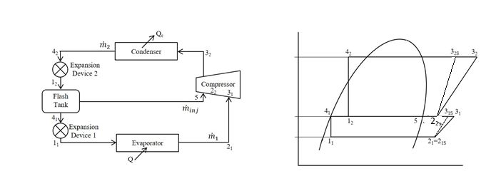
_________________________________________________________ AHRI STANDARD 1520-2022 (SI/I-P)

 APPENDIX E. METHODS FOR CALCULATING
 CENTRIFUGAL COMPRESSORS PERFORMANCE -
 INFORMATIVE
E1. Compressor Performance Parameters

Centrifugal Compressor thermodynamic performance is historically represented with dimensionless parameters for flow,
head, and efficiency as in B1.3. For refrigeration compressor, we will adopt variations on the parameters used by Brasz in
B1.2 shown in Equations E1, E2, and E3 below.

 ̇ 0
 Flow Factor: = E1
 0 0

 Δℎ
 Head Factor: = 02
 E2

 Δℎ
 Isentropic Efficiency: = Δℎ E3

Where ̇0 is suction mass flow, 0 is suction density, 0 is suction sonic velocity, Δℎ is isentropic enthalpy rise, and Δℎ is
the actual enthalpy rise. With the exception of FF the other two parameters are dimensionless. The impeller diameter
squared term (D²), inB.1.2, has been taken out of the denominator for proprietary reasons and it is a constant throughout the
operating range.

 E1.1 Parasitic Losses

 The above compressor performance parameter only pertains to the aerodynamic or thermodynamic performance.
 There are other losses to be accounted for including but not restricted to bearings, motor windage, motor electrical,
 and variable frequency drives. Efficiency will be defined based on input power of the unit under test (UUT) to
 account for the parasitic losses. The calculation method is outlined below.

 E1.2 Method

 Figure E1 is a schematic of a two-stage compressor with economizer injection. State points are defined at the
 compressor flanges for all inlets and exits. Mass flow is defined at two of the three state points.

 Figure E1: Cycle schematic and pressure-enthalpy diagram for a two-stage compressor with vapor
 injection using a flash tank economizer

 17
_________________________________________________________ AHRI STANDARD 1520-2022 (SI/I-P)

State point 22s which is at the injection flow inlet pressure represents a mixed-out flow condition of the primary flow and
injection flow. The mixed-out state point 22s is at the same pressure as the exit of the first stage and the economizer.
However, the enthalpy of state point 22s is calculated by Equation E10. The isentropic state point at the exit of the first stage
is used and does not require measurement of first stage exit temperature. This is consistent with ASHRAE Standard 225.
Equations E4, E6 and E8 are in SI units and E5, E7 and E9 are in I-P units.

Flow factor, shall be calculated using Equation E4 for SI units or Equation E5 for I-P units:

 ̇1
 21 = E4
 21 21
 ̇
 21 = 3600 1 E5
 21 21
 (ℎ3 −ℎ2 )
 = 221
 ∙ 1000 E6
 (ℎ3 −ℎ2 )
 = ∙ 25,037 E7
 221
 [ ̇1 (ℎ31 −ℎ21 )+ ̇2 (ℎ32 −ℎ22 )]
 =
 × 100 E8
 [ ̇1 (ℎ31 −ℎ21 )+ ̇2 (ℎ32 −ℎ22 )]
 =
 × 0.02931 E9
 ( ̇1 ℎ31 + ̇5 ℎ5 )
 ℎ22 = ̇2
 E10

 E1.3 Extension to different number of stages

 For more than two stages, the method outlined in E1.2 can be extended. For multi-stage compressors, the flow factor
 shall be calculated for the first stage only. Equations E11-E14outline the estimation of head factor and overall
 efficiency. Equations E13 and E14 are similar to E8 and E9 and will be used for estimating the mixed-out conditions
 for the stage receiving the economized flow.

 (ℎ3 −ℎ2 )
 = ∙ 1000 E11
 221
 (ℎ3 −ℎ2 )
 = ∙ 25,037 E12
 221
 [∑
 =1 ̇ (ℎ3 −ℎ2 )]
 =
 × 100 E13
 [∑
 =1 ̇ (ℎ3 −ℎ2 )]
 = × 0.02931 E14

 18
_________________________________________________________ AHRI STANDARD 1520-2022 (SI/I-P) E2. Example for calculation of Performance The compressor manufacturer should provide performance parameters in a tabular format for both stages segmented by inlet guide vane (IGV), speed, etc. Table E1 is an example of a fixed speed R134a compressor with IGVs. Table E2 is an example calculation using the data in Table E1. Table E1. Stage Performance Data IGV (Surge) (Choke) (deg) 90 90 90 90 90 90 21 0.0154 0.0175 0.0190 0.0208 0.0216 0.0219 1 0.5543 0.5284 0.4972 0.4280 0.3669 0.3109 1st Stage 0.7147 0.7297 0.7359 0.7008 0.6490 0.5669 IGV (Surge) (Choke) (deg) 75 75 75 75 75 75 21 0.0149 0.0164 0.0179 0.0198 0.0206 0.0210 1 0.5394 0.5181 0.4887 0.4118 0.3483 0.2927 0.7126 0.7231 0.7305 0.6878 0.6378 0.5480 IGV (Surge) (Choke) (deg) 90 90 90 90 90 90 21 0.0154 0.0175 0.0190 0.0208 0.0216 0.0219 2nd Stage 2 0.5075 0.4909 0.4794 0.4291 0.3766 0.3027 IGV (Surge) (Choke) (deg) 75 75 75 75 75 75 21 0.0149 0.0164 0.0179 0.0198 0.0206 0.0210 2 0.5070 0.4915 0.4766 0.4197 0.3623 0.2836 Table E2. Two Stage Performance Parameters Segmented by IGV R134a Step 1 Inputs Parameter Variable Value Unit Notes Saturated Suction Temperature Tsat, suct 37.76 °F Suction Superheat SH 0.78 R Saturated Discharge Temperature Tsat, disch 95.73 °F Subcooling SC 0.00 R Refrigerating Capacity Q 207.73 Tons Step 2 Calculate Flange Conditions Suction Pressure P21s 47.615 Psia Suction Temperature T21s 38.54 °F Suction Density 21s 1.0035 lb/ft³ 19
_________________________________________________________ AHRI STANDARD 1520-2022 (SI/I-P) Suction Enthalpy H21s 172.35 Btu/lb Suction Entropy S21s 0.4125 Btu/lb Suction Sonic Velocity A21s 482.4 ft/s Discharge Pressure P31 130.10 psia Lvg Condenser Enthalpy H42 107.30 Btu/lb Step 3 Goal Seek on FF to meet P4 Flow Factor for 90 deg IGV FF90 0.01895 ft² Goal Seek on FF along the 90 deg IGVuntil discharge pressure meets user input Discharge Pressure Difference P32, 90 0.0000 Step 4 Table Lookup First Stage HF 1 at 90 deg IGV for FF = 0.019 HF1, 90 0.4977 EFF OA at 90 deg IGV for FF = 0.019 EFFOA, 90 0.7358 Second Stage HF2 at 90 deg IGV for FF = 0.019 HF2, 90 0.4801 Step 5 Calculate Cycle and Mass Flow with Economizer Pressure First Stage, 90deg IGV Mass Flow for 90 deg IGV m21, 90 9.174 lb/s Isentropic Enthapy Rise h31s-21, 90 4.626 Btu/lb Discharge Isentropic Enthalpy H31s, 90 176.97 Btu/lb Discharge Pressure P31, 90 80.1 psia Economizer Saturation Temperaure T5, 90 66.01 °F Entering Evaporator Enthalpy h11, 90 97.13 Btu/lb Economizer Lvg Vapor Enthalpy h5, 90 175.93 Btu/lb Economizer Lvg Vapor Density 5, 90 1.676 lb/ft³ Economizer Lvg Vapor Sonic Velocity a5, 90 476.8 ft/s Vapor Quality Entering Economizer x12, 90 0.1290 Economizer Injection Mass Flow m5, 90 1.359 lb/s Second Stage, 90deg IGV Ent 2nd Stage Isentropic Enthalpy h22s,90 176.84 Btu/lb Eq. E10 Ent 2nd Stage Isentropic Entropy s22s, 90 0.4122 Btu/lb Isentropic Enthalpy Rise h32s-22s, 90 4.360 Btu/lb Discharge Isentropic Enthalpy H32s, 90 181.20 Btu/lb 20
_________________________________________________________ AHRI STANDARD 1520-2022 (SI/I-P) Discharge Pressure P32, 90 130.1 psia Goal Seek to meet specified outlet pressure (sat temp) First Stage, 75deg IGV Mass Flow for 75 deg IGV m21, 75 8.54 lb/s Isentropic Enthalpy Rise h31s-21, 75 4.589 Btu/lb Discharge Isentropic Enthalpy H31s, 75 176.94 Btu/lb Discharge Pressure P31, 75 79.8 psia Economizer Saturation Temperature T5 65.77 °F Entering Evaporator Enthalpy h11, 75 97.05 Btu/lb Economizer Lvg Vapor Enthalpy h5, 75 175.90 Btu/lb Economizer Lvg Vapor Density 5, 75 1.669 lb/ft³ Economizer Lvg Vapor Sonic Velocity a5, 75 476.9 ft/s Vapor Quality Entering Economizer x12, 75 0.1300 Economizer Injection Mass Flow m5, 75 1.276 lb/s Second Stage, 75deg IGV Ent 2nd Stage Isentropic Enthalpy h22s, 75 176.80 Btu/lb Eq. 11 Ent 2nd Stage Isentropic Entropy s22s, 75 0.4122 Btu/lb Isentropic Enthalpy Rise h32s, 75 4.397 Btu/lb Discharge Isentropic Enthalpy h32s, 75 181.20 Btu/lb Discharge Pressure P32, 75 130.1 psia Goal Seek to meet specified outlet pressure (sat temp) IGV 90 Refrigerating Capacity Q 207.0 Tons IGV 75 Refrigerating Capacity Q 192.9 Tons IGV 90.8 Inlet Guide Vane to Meet Discharge Pressure IGV 90.77 deg Interpolate between IGVs to meet input Refrigerating Capacity Suction Mass Flow m21 9.206 lb/s Calculation of Compressor Thermodynamic Performance Step 6 IGV 90.8 Flow Factor (eq. 3) FF 0.0190 ft² 21
_________________________________________________________ AHRI STANDARD 1520-2022 (SI/I-P) HF 1 at 90.8 deg IGV for FF = 0.019 HF1 0.4979 EFF OA at 90.8 deg IGV for FF = 0.019 EFFOA 0.7362 HF 2 at 90.8 deg IGV for FF = 0.019 HF2 0.4799 Isentropic Enthalpy Rise of First Stage h31s-21 4.628 Btu/lb Isentropic Enthalpy Lvg. First Stage H31s 176.98 Btu/lb Pressure Leaving First Stage P31 80.1 psia Economizer Saturation Temperaure T5 66.03 °F Economizer Injection Enthalpy h5 175.93 Btu/lb Density Leaving First Stage 31s 1.676 lb/ft³ Sonic Velocity Leaving First Stage a31s 476.8 ft/sec Vapor Quality Entering Economizer x12 0.1290 Economizer Injection Mass Flow m5 1.363 lb/s Enthalpy Entering Second Stage h22s 176.84 Btu/lb Eq. 11 Isentropic Enthalpy Rise of Second Stage h32s-22s 4.358 Btu/lb Total Power P 127.1 kW 0.28% from measured power E3. Symbols and Subscripts NS = number of compressor stages = head factor for compressor stage i 21 = refrigerant sonic velocity entering the first compressor stage, m/s (ft/s) η = isentropic efficiency, % (%), for a two-stage stage compressor with Vapor Injection ̇1 = refrigerant mass flow rate entering the compressor, kg/s (lbm/h) ̇2 = refrigerant mass flow rate after mixing the injection flow and inlet flow, kg/s (lb m/h) ̇ = refrigerant mass flow rate entering the compressor stage i, kg/s (lbm/h) ̇5 = refrigerant mass flow rate injected into compressor at intermediate pressure, kg/s (lbm/h) ℎ21 = specific enthalpy of refrigerant vapor at suction pressure and temperature entering the compressor, kJ/kg (Btu/lbm) ℎ22 = specific enthalpy of refrigerant vapor after mixing the intermediate pressure flow at state point 5 with the flow at state point 31s shall be calculated using Equation E10, kJ/kg (Btu/lbm) ℎ31 = specific enthalpy of refrigerant vapor at intermediate pressure following an isentropic compression of the refrigerant from compressor suction pressure and temperature, kJ/kg (Btu/lb m) ℎ32 = specific enthalpy of refrigerant vapor at compressor discharge pressure following an isentropic compression of the refrigerant from state point 2 2s, kJ/kg (Btu/lbm) h5 = specific enthalpy of refrigerant injected into compressor calculated based on measured pressure P5 and temperature T5, kJ/kg (Btu/lbm) ℎ2 = specific enthalpy of refrigerant vapor at suction pressure and temperature entering the compressor stage i, kJ/kg (Btu/lbm) ℎ3 = specific enthalpy of refrigerant vapor at the discharge pressure for stage i following an isentropic compression of the refrigerant from compressor stage suction pressure and temperature, kJ/kg (Btu/lb m) P = total power input to the UUT (unit under test), kW (kW) 22
You can also read