TELECOM FIBER EDITING TOOLS REFERENCE GUIDE
←
→
Page content transcription
If your browser does not render page correctly, please read the page content below

TELECOM FIBER
                                  EDITING TOOLS
                                  REFERENCE GUIDE
                                  Version 1.2

Prepared by:

Esri
380 New York Street
Redlands, California 92373-8100
Phone: (909) 793-2853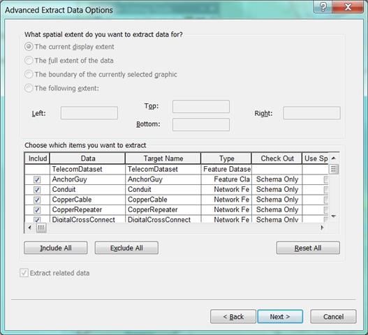
Telecom Fiber Editing Tools Reference Guide

Table of Contents

1.     Overview and Getting Started .................................................. 2
2.     Installation and Configuration ................................................. 3
     2.1.Installing the tools ..................................................................... 3
     2.2.Enabling the Esri Fiber Editing Toolbar ......................................... 3
3.     Standard Editing Practice and Workflow .................................. 5
4.     Known Limitations of the Tools ................................................ 6
5.     Important Configuration Steps ................................................. 7
     5.1.Creating New Fiber Cable & Device Configurations ......................... 7
     5.2.Snapping Environment ............................................................. 10
     5.3.Dynamic Values ...................................................................... 11
     5.4.Using the Fiber Tools With an Enterprise GDB ............................. 15
     5.5.Migration of Existing Databases ................................................. 20
6.     Tools Overview....................................................................... 21
     6.1.Workspace Commands ............................................................. 22
       6.1.1. Open Workspace ............................................................. 22
       6.1.2. Close Workspace ............................................................. 22
     6.2.Standard Editor Commands ...................................................... 22
       6.2.1. Start Editing ................................................................... 22
       6.2.2. Stop Editing ................................................................... 22
       6.2.3. Editing Options ............................................................... 23
       6.2.4. Attribute Editor ............................................................... 23
     6.3.Creating Cables and Devices ..................................................... 24
     6.4.Viewing, Editing and Tracing Cable/Device Connections ................ 25
       6.4.1. Splice Editor ................................................................... 25
       6.4.2. Connections Editor .......................................................... 26
       6.4.3. Fiber Strand Tracing ........................................................ 27
7.     The Telecom Data Model ........................................................ 29
     7.1.Fiber Creation ......................................................................... 31
     7.2.Device Creation ....................................................................... 32
     7.3.Connections Editor ................................................................... 33
     7.4.Splice Editor ........................................................................... 34
     7.5.Attributes and Relationship Editing ............................................ 34
       7.5.1. Conduits, Ducts, and Innerducts ....................................... 35
       7.5.2. FiberCables, Ducts, and Innerducts ................................... 36
8.     Items For Consideration ......................................................... 38

                                                  i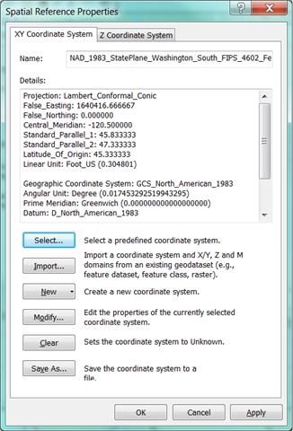
Telecom Fiber Editing Tools Reference Guide

1.    Overview and Getting Started

This document is for reference by individual end users responsible for the
generation, editing, and tracing of fiber telecommunications network data
with the Esri Telecom Fiber Tools toolbar. These tools were developed by
ESRI and made freely available for download along with a supporting data
model and application source code from ESRI’s website and is intended for
use with version 10.2 of ESRI’s ArcGIS for Desktop Standard or Advanced
(ArcEditor or ArcInfo) software license level.

This document assumes the reader is familiar with ESRI’s ArcGIS Desktop
product from an end user’s perspective as well as with ESRI geodatabase
concepts, including feature classes, tables, relationship classes, and
geometric networks.

The tools described are specific to the editing and management of fiber optic
telecommunications and do not offer specific functionality for copper (or
other) networks at this time.

The tools provide specialized functions for editing and maintaining fiber
telecommunications and conduit network map features, including network
devices, fiber cables, splice closures, conduit, and structures. In addition
they facilitate configuration and management and tracing of the lower level
interconnectivity and relationships of individual ports, fiber strands, fiber
splices, buffer tubes, and duct work.

This document provides an introduction to the end user functions
available from the Telecom Fiber Tools toolbar, including important
configuration details that can impact the correct operation of the
tools.

Please read the installation and configuration sections to ensure
your editing environment is setup correctly before attempting to use
the tools.

                                                                                Page | 2
Telecom Fiber Editing Tools Reference Guide

2.      Installation and Configuration
2.1. Installing the tools
The Esri Telecom Fiber Tools add-in must be installed following the
installation of the ArcGIS Desktop application. Note that ArcGIS for Desktop
Standard level is the minimum license required in order to use these tools.
ArcGIS for Desktop Basic will not work with these tools.

How to install the tools

     1. For instructions on how to install/uninstall the tools please see the
        document Getting Started.pdf

2.2. Enabling the Esri Fiber Editing Toolbar
Once you have installed the Add-In, you
can access the fiber editing tools via the
toolbars menu if not already enabled. To
do this click Customize->Toolbars->
and select Esri Fiber Editing from the
list. The toolbar will appear floating in
the ArcMap window.

The Esri Fiber Editing Toolbar should now be shown as follows:

                                                                                    Page | 3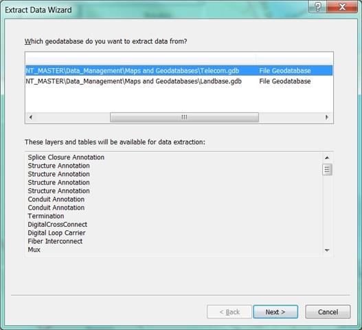
Telecom Fiber Editing Tools Reference Guide
The tools available on the toolbar allow you to:
Open and close a fiber editing workspace
Start and stop an edit session
Select and edit telecom network map features and their
attributes.
Specify the configuration of fiber cables and telecom devices
Configure the interconnectivity of devices, splices, and fiber at the
level of individual ports and strands
Trace the fiber network at the fiber strand level
View diagnostic log information associated with the tools
More details on the individual tools and their operation are detailed in
section 6 of this document.
Page | 4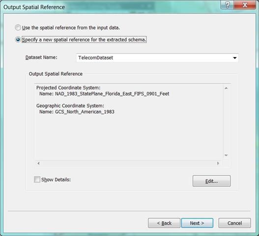
Telecom Fiber Editing Tools Reference Guide

3.      Standard Editing Practice and Workflow

The Esri Fiber Editing tools perform some complex editing operations; for
instance when a cable is created it is not simply creating one feature but
creating a whole series of features that are related and interdependent on
each other. A cable consists of multiple buffer tubes and within those lives
the many fiber strands that provide the communication media.

The standard editing workflow for using these tools is as follows:

     1. Use the fiber editing toolbar Open Workspace command to select
        and validate an Esri Fiber tools workspace

     2. Use the fiber editing Start Editing command to start an edit session

     3. Use the Create Features window to create and place cables and
        devices

     4. Use the Fiber Splice tool to edit or view connectivity information
        between cables

     5. Use the Fiber Device Connections tool to edit or view connectivity
        information between cables and devices

     6. Use the Fiber Network Trace command to run a detailed connectivity
        trace along a strand within a cable

     7. Use the Stop Editing command to save and close your edits

     8. Use the Close Workspace command to close out your editing session

Due to these many complex relationships users of the fiber editing tools
must adhere to some basic editing restrictions and workflows. Some of these
are limitations of the how the tools are implemented at this time and special
care must be taken to confirm to these rules.

Some key points of operation when using these tools are:

     1. Do not use an edit session on a telecom workspace without using the
        fiber editor toolbar to first open that workspace. Without first opening
        a telecom workspace for editing means that none of the event listeners
        will fire which create, maintain and remove the appropriate

                                                                                  Page | 5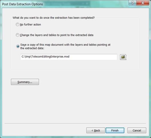
Telecom Fiber Editing Tools Reference Guide

        relationships between the objects in the data model. Doing so will
        invalidate the integrity of the data model contents.

     2. Do not use the standard editor toolbar to perform complex geometry
        operations that recreate or split features. Doing so will invalidate the
        integrity of the data model as logic does not exist at this time to
        update the relationships between the new geometry and its previously
        related items (conduit, buffer tubes, and strands). Using standard
        editing tools to move the vertices of an existing cable IS allowed since
        this does not recreate the feature.

4.      Known Limitations of the Tools

Known limitations of the tools at this time:

     1. Mid cable splicing of cables is not support whereby the cable sheath is
        cut and several strands are pulled out to service a business or
        residence. All cable splicing must exist at the end points of cables. As
        previously stated using the Split tool to cut the cable will invalidate the
        integrity of the model. If you need to do this you must model this by
        deleting the cable and creating 2 cables so that a splice location can be
        placed.

     2. Tracing is only supported through cables and splice closures. If a trace
        reaches a device the trace will stop at the device and port # it is
        connected to. The trace mechanism at this time does not have enough
        information on the internal workings of devices to decide how to
        continue the trace on the input or output side. This logic will vary per
        device.

                                                                                    Page | 6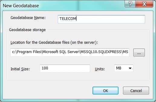
Telecom Fiber Editing Tools Reference Guide
5. Important Configuration Steps
5.1. Creating New Fiber Cable & Device
Configurations
The 10.1 (later versions) and 10.2 version of the Esri
Fiber Editing tools use the standard Create Feature and
Feature Template mechanisms. The default database and
map document come with a default set of cable and
device configurations. This set of configurations is not all
inclusive and you will need to add to the list of items
available.
For example to add a new configuration of cable do the
following steps:
Open the telecom workspace.
Start an Edit Session.
Open the Create Features window (shown to the
right)
Right click an existing cable configuration and
Copy it. A new item named “Copy of …” will
appear.
Right click the new item and click Properties to edit this feature
template.
Page | 7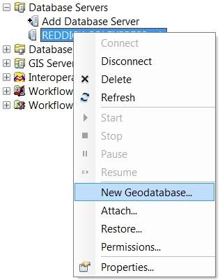
Telecom Fiber Editing Tools Reference Guide
Enter a new Name (removing “Copy of”), Description and Tags
corresponding to the new cable configuration you are creating.
Scroll down in the template properties to find the entries for Number
of Buffers and Number of Fibers per Buffer Tube. Enter the correct
values corresponding to your new cable configuration.
Click OK to update this new template item.
You should now see your new cable configuration in the template list.
Page | 8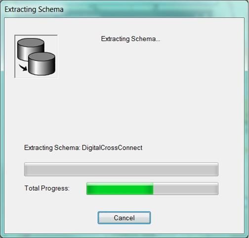
Telecom Fiber Editing Tools Reference Guide

The same mechanism can be used to create new Device port configurations.

More more information on editing feature templates please reference:
http://resources.arcgis.com/en/help/main/10.2/index.html#/About_feature_templates/01
m700000022000000/

                                                                                    Page | 9
Telecom Fiber Editing Tools Reference Guide
5.2. Snapping Environment
Geometric network connectivity is used by some of the tools to identify the
specific cables and connections being used during connectivity operations. In
order for this connectivity to work properly certain features need to be
snapped to other features.
The following table lists some of the common types of snapping relationships
that are required by related objects and operations such as splicing:
Items to snap Reason
Cable to Cable endpoints Required by any cables you want to
splice together
Cable end points to Splice Closure All cable splices must exist within a
splice closure
Cable end points to Device Cables must be snapped to device in
order to make connections to it
Proper snapping of Fiber Cables, Devices, Terminations, and Splice
Closures is mandatory for the many of the Telecom Editing tools to
work.
If you do not see any features that you expect in any dialog drop downs
make sure that the features are snapped to the appropriate objects.
Page | 10Telecom Fiber Editing Tools Reference Guide
5.3. Dynamic Values
The Esri Telecom Fiber Tools utilizes a dynamic values capability that auto
populates certain feature field values. This allows us to auto populate
content field values such as Creation User, Last User, Creation and Edit time
stamps etc without the need for user input. The fields that are auto
populated is controlled by a table named DynamicValue. This table can
be edited to include addition fields that you wish to have auto-populate.
Some of these values in this table are NOT optional and removing
them from the configuration setup will break the operation of the
tools. These important field values are highlighted in the table
below:
A DynamicValues.xml file is include in the Maps and GDBs folder of the tools.
This file contains a base configuration of the minimal values required for the
tools to operate. When creating new editing database be sure to populate
the DynamicValue table with the contents of this xml file. This can be done
as follows:
Within the Catalog window of ArcMap find the DynamicValue table in
the new GeoDatabase.
Right click on this table and select Load->Load XML RecordSet
Document.
Page | 11Telecom Fiber Editing Tools Reference Guide
Browse to the location of the DynamicValues.xml file provided with the
install.
Click Next.
Accept the defaults on this next dialog and click Finish. The XML
values will be imported.
Page | 12Telecom Fiber Editing Tools Reference Guide
To confirm the import was successful. Find the DynamicValues in the
Table of Contents…
Click List By Source
Select the DynamicValue table and right click.
Select Open to open the attribute table.
Page | 13Telecom Fiber Editing Tools Reference Guide
The table should now show valid values as follows:
Page | 14Telecom Fiber Editing Tools Reference Guide
5.4. Using the Fiber Tools With an Enterprise GDB
The Esri Telecom Fiber Editing tools are fully enterprise GDB ready. In order
to create a new GDB in the correct spatial projection of your choice please
follow these steps:
Open the original map document Fiber Network Data
Management.mxd shipped with the template download.
From the Catalog window create a new enterprise geodatabase
on the DB platform of your choice.
Use the Customize->Toolbars menu to open the Distributed
Geodatabase toolbar and click the Extract Data tool (far right) to
initiate a GDB to GDB export specifying the new projection
information. If this tool is not enabled then you may not have
the correct license level to use these tools (if so please read
section 2.1 of this document).
Select the Telecom geodatabase that we will extract the schema
from....
Page | 15Telecom Fiber Editing Tools Reference Guide
Click Next. Specify Schema Only and set the output location to the
enterprise GDB we created above. Ensure the Advanced Options
check box is selected.
Leave the following options as the defaults...
Page | 16Telecom Fiber Editing Tools Reference Guide
Now we get to select a new local projection for our output
geodatabase. Click Edit to see a list of projections to choose from...
Page | 17Telecom Fiber Editing Tools Reference Guide
The Spatial Reference Properties dialog showing the new projection
(in this case for Washington State Plane South)...
Next choose a location for a new MXD that will be created
referencing the enterprise database we will populate with the new
schema...
Page | 18Telecom Fiber Editing Tools Reference Guide
Click Finish and the extract process will run re-projecting the
database schema at the same time...
Import the minimum required Dynamic Values settings (see
section 5.3 of this document). These settings need to be imported
for the editing tools to function correctly.
Register the database as versioned. This will enable multi-user
versioned access. Do this by right clicking on the TelecomDataset
and selecting Register As Versioned. Click OK when prompted.
Page | 19Telecom Fiber Editing Tools Reference Guide
5.5. Migration of Existing Databases
As updates to the telecom data model are made we will attempt to provide
mechanisms for users to update their existing databases through the
inclusion of GP models that perform the required changes. However given
the nature of the tools (being unsupported sample implementations) we will
not always be able to provide such migration support when more complex
updates are done.
We will try to minimize the impact of any changes made and record details
of all such changes between versions to aid in any migration efforts.
Page | 20Telecom Fiber Editing Tools Reference Guide
6. Tools Overview
The Telecom Fiber Editing Tools provide you consolidated access to standard
commercial, off the shelf (COTS) selection and editing functions as well as
customized tools for defining the characteristics, connectivity, and inter-
relationship of fiber telecommunications data elements, including fiber
bundles, conduit, devices, and splices. The toolbar also provides basic fiber
telecommunications network tracing functionality.
A number of the tools are only active within an edit session in ArcMap and
also only when certain types of map features are selected (devices, fiber
cables etc).
Some tools will automatically engage the ArcMap Feature Selection tool since
they operate on a selection set and will populate information when the user
selects one or more features on the map. If necessary, add layers to the list
of selectable layers by switching to the “List By Selection” tab in the Table of
Contents and checking them.
The Telecom Fiber Editing Tools contain a number of standard ArcMap tools
as well as specialized tools and commands specifically created for creating,
managing, and editing fiber telecommunications network connectivity, both
among map features, such as fiber cables, devices, and splice closures, as
well as lower level connectivity and relationships such as fiber strands and
device ports, and duct and inner ducts to fiber strands. These tools operate
against a standardized ESRI geodatabase model.
Page | 21Telecom Fiber Editing Tools Reference Guide
The following sections describe each command on the Telecom Fiber Editing
Tools toolbar.
6.1. Workspace Commands
6.1.1. Open Workspace
This tool allows you to open a particular telecom fiber workspace. A
workspace must be select in order to initialize the tools for use. Performing
editing on a telecom workspace without first opening it is not supported and
may invalidate the workspace. The tools on the fiber editing toolbar will not
be enabled until this step is carried out.
The act of opening a workspace carries out validity checks on the database
selected by the user. If a workspace is found to be invalid please check the
Log Window for more details on the cause.
6.1.2. Close Workspace
This tool closes the current telecom editing workspace after you have
finished an edit session. Closing the workspace will disable all telecom fiber
editing tools.
6.2. Standard Editor Commands
These commands are part of the standard ArcMap Editor toolbar and have
been added to the Telecom Fiber Editing toolbar for convenience.
6.2.1. Start Editing
This is the standard Start Editing command. Starts an edit session on the
current telecom workspace.
6.2.2. Stop Editing
This is the standard Stop Editing command. Stops the edit session on the
current telecom workspace.
Page | 22Telecom Fiber Editing Tools Reference Guide
6.2.3. Editing Options
This is the standard Editor Options command. Gives users access to the
standard editing options such as tolerances for snapping, version conflict
resolution etc.
6.2.4. Attribute Editor
This command opens the Attributes dialog box which displays the attributes
of all selected features. The attributes may be edited if an edit session has
been started.
This tool also allows you to create tabular
records, or objects, related to selected
features, such as Ducts and Innerducts of a
Conduit, and to relate selected features
participating in a relationship class, such as
Ducts and Fiber cables. This functionality
can be accessed through the right-click
shortcut menu within the dialog when an
item has been selected.
This is the standard ArcMap tool for editing Attribute values.
Page | 23Telecom Fiber Editing Tools Reference Guide
6.3. Creating Cables and Devices
Cable and device creation is a very straight forward process
using the standard feature template editing mechanisms.
Creating a new cable or device is as simple as picking the
appropriate item in the feature palette of the Create
Features window and sketching the geometry (a line for
cables) or picking the location (a point in the case of
devices).
If the Create Features window does not show up when you
open a telecom workspace and start an edit session it can
be access as follows:
From the menu: Select Customize->Toolbars-
>Editor
From the Editor Toolbar: Click Editor->Editing
Windows->Create Features
When creating new features for some types (devices and
cables) you will notice some custom behavior beyond the
normal editing experience. As you create cables and devices
of a specific configuration a popup progress dialog will
appear briefly. This shows the progress of creating the
related features for the cable or devices type in question.
For example creation of a cable creates all the buffer tubes
and strands that are contained within that cable. The tools
take care of creating all these additional database records
rather than making the user populate this information.
If you do not see this dialog then make sure you
are not editing the database outside of an edit
session where a telecom workspace has been
opened (see section 6.1.1). This step must be
carried out for the tools to work as expected.
For more information on configuring new device
and cable types please see section 5.1.
Page | 24Telecom Fiber Editing Tools Reference Guide
6.4. Viewing, Editing and Tracing Cable/Device
Connections
6.4.1. Splice Editor
The Splice Editor tool allows users to
define the fiber strand ranges to
connect to other fiber cable sections
terminating their length at a given
splice closure. The tool also allows
users to specify the type of physical
fiber connection and any losses
associated with it.
The Cable A and Cable B controls list the cables connected (snapped) to the
selected SpliceClosure. Select the correct features for the Splice Closure,
Cable A, and Cable B controls from the available options. Cable A should be
the cable upstream from the splice. If necessary, click the Flash links to
highlight the selection in the map view for confirmation.
Available fiber ranges are shown below each dropdown for the currently
selected cable. If there are no available ranges for a cable, the dialog will
state ‘No available ranges!’ below the dropdown.
Define the Range A, Range B, Loss, and Type values each Fiber Splice within
the SpliceClosure and then set these values by clicking the Update button in
the lower right. An error message will display if an update is attempted with
invalid range values.
Fiber cables must be snapped at their endpoint to a splice closure and
another fiber cable or it will not be possible to configure the connectivity
(for more information on snapping requirements see section 5.2).
Page | 25Telecom Fiber Editing Tools Reference Guide
6.4.2. Connections Editor
The Connections Editor allows users to specify the connectivity between
cables and devices (Digital Cross Connects, Multiplexers, etc.) including the
ranges used at the individual fiber level and both the input and output port
level.
The dialog lists devices and any
cables connected to it in the From
and To Device/Cable combo box
drop down controls. Select the
appropriate device and cable from
the available options. If necessary,
click the Flash links to highlight
the selection in the map view for
confirmation.
Define the From Range and To Range values for the ports of the device that
the FiberCable fiber strands connect to and then set these values by clicking
the Update button. If there are no available ranges for a selected device or
cable, the dialog will state ‘No available ranges!’ below the corresponding
dropdown. An error message will display if an update is attempted with
unavailable or invalid range configurations.
The results of edits can be seen by clicking the Attributes tool from the
Editor or Telecom Editing Tools toolbar and drilling down from the device to
the related port records in the Attributes dialog.
Fiber cables must be snapped to devices at their endpoint or it will not be
possible to configure connectivity (for more information on snapping
requirements see section 5.2).
Page | 26Telecom Fiber Editing Tools Reference Guide
6.4.3. Fiber Strand Tracing
The Telecom Fiber Editing Tools
toolbar provides the ability to
trace a specified port or fiber
strand from a selected device or
fiber cable based on the
interconnectivity configured with
the other Telecom Editing tools.
The dialog will be displayed listing the selected devices or fiber cables in the
Existing Cables/Devices combo box drop down control on the dialog. Select
the device or FiberCable containing the Port or Fiber to be traced from the
drop down control and specify the Port or Device number in the Unit Number
(strand/port) text box. Notice that the feature specified in the dialog will be
highlighted in the map view. The feature can also be highlighted by clicking
the Flash link. Only a single fiber strand or port can be traced at a time.
Click the Run Trace button on the Fiber Trace dialog to run the analysis. The
results of the trace will be displayed in the Trace Results dialog and selected
in the map. The Trace Results dialog lists details of the trace, including an
ordered list of all of the devices, splice closures, and fiber cables that the
fiber strand or port is connected to.
If necessary, choose the
Selection>Zoom to Selected
Features option to set the map
extents so that you can see the
entire route of the traced fiber or
port connections.
The Start point of the trace is
always highlighted in Yellow.
Nodes/Features that are locatable
geographically on the map are
highlighted in Green; right click on
these items to flash their location
on the map.
Page | 27Telecom Fiber Editing Tools Reference Guide
Note: At this time the telecom data model does not support tracing through
devices. A trace that is executed will pass through any number of cables and
splice closures but will stop when it reaches a device and port on that
device. Internal logic of how to trace through devices has not been
implemented at this time.
In addition to the specialized, low level fiber telecommunication ArcMap
provides standard capability for tracing the TelecomNetwork and
ConduitNetwork features based on snapped, topological connectivity with the
Utility Network Analyst. For more information on standard tracing of
geometric networks with the Utility Network Analyst reference:
http://resources.arcgis.com/en/help/main/10.2/index.html#//002r0000002s
000000
Page | 28Telecom Fiber Editing Tools Reference Guide
7. The Telecom Data Model
The Telecom Editing Tools have been built to work against a standardized
fiber telecommunications data model1. As such, it is important that the
feature class and table names and relationships of the database are not
altered.
All the features in the model are created and edited with standard ArcMap
editing capabilities and feature template editing capabilities. Some features
however exhibit custom functionality when created, such as the creation of
more than one feature per user feature sketched. As a result these objects
should not be edited directly (outside of an fiber editing workspace session)
with the standard edit tools unless you fully understand the model and the
consequences of performing such edits.
For more information on Creating New Features and Edit Templates
reference:
http://resources.arcgis.com/en/help/main/10.2/index.html#//01m70000002
2000000
The data model includes two Geometric Networks: TelecomNetwork and
ConduitNetwork. The following lists the respective feature classes in each
network and their roles in the network:
TelecomNetwork
o DigitalCrossConnect-Simple Junction
o DigitalLoopCarrier-Simple Junction
o FiberCable-Complex Edge
o FiberInterconnect-Simple Junction
o Multiplexer-Simple Junction
o OpticalRepeater-Simple Junction
o PatchPanel-Simple Junction
o SpliceClosure- Simple Junction
o Splitter-Simple Junction
o TelecomNetwork_Junctions- Simple Junction
o Termination-Simple Junction
ConduitNetwork
o Conduit-Complex Edge
1
This model is based on, but varies slightly from Esri’s telecom data model that was originally published back in
2007.
Page | 29Telecom Fiber Editing Tools Reference Guide
o Structure-Simple Junction
o ConduitNetwork_Junctions-Simple Junction
Inclusion of these features in Geometric Networks facilitates advanced
management of feature interconnectivity functions.
Note that since Fiber Cables and Conduits are Complex Edges in the
ConduitNetwork and TelecomNetwork, these objects will not be split into
two separate features when a new Structure or object is placed along
them.
Devices and splice closure junctions must be properly snapped to fiber edges
or a number of the Telecom Editing Tools will not function properly. For
example, both the Splice Editor and Connections Editor tools rely on properly
snapped elements to determine the from and to features to display in the
drop down combo box controls. If the network features are improperly
snapped, the dropdown selection controls will be empty and the connectivity
cannot be specified.
For more information on Geometric Network concepts reference:
http://help.arcgis.com/en/arcgisdesktop/10.2/help/index.html#//002r00000
001000000.htm
For more information on the Snapping Environment reference:
http://help.arcgis.com/en/arcgisdesktop/10.2/help/index.html#//001t00000
03t000000.htm
In addition to the network feature classes, the data model includes a number
of tables and relationship classes specific to defining and managing the
relationships and connectivity of the lower level telecommunications
elements, such as individual ducts, sub-ducts, fibers, and ports.
TheTelecom Editing Tools operate against these tables and simplify editing of
this detailed, low-level telecommunication network connectivity.
The remainder of this section describes how the various edit operations
operate against these tables and relationships.
Page | 30Telecom Fiber Editing Tools Reference Guide
7.1. Fiber Creation
When a Fiber Cable is created or updated, the appropriate numbers of
records are created in the BufferTube and Fiber tables in the geodatabase
and both are related to the relevant FiberCable feature.
In addition, the new, individual Fibers are evenly allocated to the new
BufferTubes via the BufferTubeHasFiber relationship class. For example, if
12 Fiber strands and 4 Buffer Tubes are created, 3 Fibers are related to each
BufferTube. The illustration below shows the various updates and
relationships resulting from such a fiber cable creation.
The table below lists the entities affected by the creation of a Fiber Cable.
Operates on Updates Relationship Classes
FiberCable feature class BufferTube table BufferTubeHasFiber
FiberCableHasBufferTube
Fiber table FiberCableHasFiber
Page | 31Telecom Fiber Editing Tools Reference Guide
7.2. Device Creation
When a device is created, the tool creates the relevant number of port
records in the port table related to the device (as elaborated in the table
below). A port record is created for each input and output port, so for
example, a device creation with 12 input ports and 12 output ports would
results in 24 total new ports related to the device as shown below. In
addition, the Port Type attribute will be set appropriately on the records.
The table below lists the entities affected by use of this tool.
Operates on Updates Relationship
Classes
DigitalCrossConnect DXCPort table DCCHasPorts
feature class
DigitalLoopCarrier feature DLCPort table DLCHasPorts
class
FiberInterconnect feature FICPort table FICHasPorts
class
Multiplexer MuxPort table MuxHasPorts
feature class
OpticalRepeater OptRptrPort table OPTRHasPorts
feature class
PatchPanel feature class PatchPanelPort table PatchPanelHasPorts
Splitter feature class SplitterPorts table SplitterHasPorts
Page | 32Telecom Fiber Editing Tools Reference Guide
7.3. Connections Editor
The Connections Editor allows users to specify the from and to ranges for
Fibers of Fiber Cables snapped to a device (Digital Cross Connects,
Multiplexers, etc.). When a From Range and To Range are specified for the
selected feature and updated, the Connected Fiber attribute of the devices
related ports are updated to reflect this connectivity.
In the illustration below, a Mux device has been edited with the Connections
Editor. Prior to the edit the Connected Fiber attribute of Port 20 was Null,
however after the update, Port 20 has been connected to Fiber 20 of the
Fiber Cable edge snapped to the Mux device junction in the TelecomNetwork.
The table below lists the data entities affected by use of this tool.
Operates on Updates
DigitalCrossConnect DXCPort table Connected Fiber attribute
feature class
DigitalLoopCarrier feature DLCPort table Connected Fiber attribute
class
FiberInterconnect feature FICPort table Connected Fiber attribute
class
Multiplexer MuxPort table Connected Fiber attribute
feature class
OpticalRepeater OptRptrPort table Connected Fiber attribute
feature class
PatchPanel feature class PatchPanelPort table Connected Fiber attribute
Splitter feature class SplitterPorts table Connected Fiber attribute
Page | 33Telecom Fiber Editing Tools Reference Guide
7.4. Splice Editor
The Splice Editor allows users to define the Fiber strand ranges for Fiber
Cables connected to a SpliceClosure. When a SpliceClosure is edited with
this tool, the tool creates records in the FiberSplice table indicating the from
and to connectivity of the Fiber strands of the FiberCables connected to the
SpliceClosure and relates these new FiberSplice records to the SpliceClosure
feature.
The illustration below shows a number of newly created FiberSplice records
related to a given Splice Closure; note the Cable A Fiber and Cable B Fiber
attribute values showing that Fiber #16 of the incoming FiberCable is
connected to Fiber #16 of the outgoing FiberCable.
The table below lists the data entities affected by use of this tool.
Operates on Updates Relationship Classes
SpliceClosure feature FiberSplice table SpliceClosureHasSplices
class
7.5. Attributes and Relationship Editing
In addition to the custom Telecom Editing Tools described above, the
standard ArcMap Attributes Tool is used to create some of the non-spatial
tabular elements of the telecommunications geodatabase and relate them to
the spatial telecommunications and conduit network features. This
Page | 34Telecom Fiber Editing Tools Reference Guide
functionality as it specifically relates to the telecommunications data model
is discussed below.
For further general information on editing related features and relationships,
reference:
http://help.arcgis.com/en/arcgisdesktop/10.2/help/index.html#//001t00000
0m9000000.htm
7.5.1. Conduits, Ducts, and Innerducts
Conduit can contain ducts which may themselves contain innerducts. These
physical relationships are modeled in the telecom geodatabase with
relationship classes among Conduits, Ducts, and Innerducts.
To create these entities and their relationships, a new Conduit feature is first
created with the standard Edit Template capabilities and the Attribute tool is
used to open the Attributes dialog for the selected Conduit. Ducts and
Innerducts can then be created and related to the Conduit and each other by
selecting the ‘Add New’ option from the right click pop-up menu on the Duct
or Innerduct node for the elements related to the Conduit.
As an example, the illustration below shows that the Conduit contains two
Ducts, one with six Innerducts and one with 4 Innerducts.
Page | 35Telecom Fiber Editing Tools Reference Guide
The table below lists the data entities affected by use of this tool for these
cases.
Operates on Updates Relationship Classes
Conduits feature class Ducts table ConduitHasDucts
Ducts table Innerducts table DuctHasInnerduct
7.5.2. FiberCables, Ducts, and Innerducts
FiberCables may be directly contained within a Conduit, or may be contained
within one of the Conduit’s Ducts or Innerducts. This physical relationship is
also represented by a geodatabase Relationship Classes in the telecom data
model.
To create these entities and their relationships, a Conduit feature and,
optionally one or more Ducts and/or Innerducts are created as described
above and a FiberCable is created with the fiber edit template capabilities.
The FiberCable and related Conduit can then be selected using the Edit Tool
and the Attributes dialog opened to display the FiberCable and Conduit
attributes. The selected FiberCable is related to the Conduit, Duct, or
Innerduct by selecting the ‘Add Selected’ option from the right click pop-up
menu on the Fiber Cable node of the Conduit, Duct, or Innerduct.
Note that if a Duct’s Innerducts contain FiberCable(s), those cables will only
be related to the Innerduct; in other words, the relationship is not
‘cumulative’ and even though the Duct technically also indirectly contains
the FiberCables of the Innerduct, they will only be related to the Innerduct
and not the Duct.
As an example, the illustration below shows that the Conduit contains one
Duct that directly contains six FiberCables. In addition, the Duct also
contains one Innerduct and that contains an additional three FiberCables.
Page | 36Telecom Fiber Editing Tools Reference Guide
The table below lists the data entities affected by use of this tool for these
cases.
Operates on Updates Relationship Classes
FiberCable feature class Ducts table DuctHasFiberCable
Innerducts table InnerductHasFiberCable
ConduitHasFiberCable
Page | 37Telecom Fiber Editing Tools Reference Guide
8. Items For Consideration
If you want your data to be as absolutely accurate and representative
of their real world locations as possible, FiberCables and Conduit
vertices and edges should match exactly since the Conduit actually
contains the FiberCable bundles. Use of other tools such as ArcGIS
Schematics, can provide capabilities to visual these in an offset fashion
without affecting the underlying data accuracy. However, if you
require visualization of both Fiber Cables and Conduit in a single map
view without the use of ArcGIS Schematics, you may wish to place the
Fiber Cables at a slight offset from the Conduit when digitizing the
features in ArcMap. The value of the offset should be determined
based on the typical scale at which you would view these maps. This
decision should be taken only after considering your mapping
requirements and your organizations spatial data accuracy standards.
Although it will result in less spatial data accuracy, it may well be
within tolerable error values, depending on the map scale.
Page | 38You can also read