PERGOLAS ARTOSI Measurement
←
→
Page content transcription
If your browser does not render page correctly, please read the page content below
MEASUREMENT AND ASSEMBLY MANUAL

PERGOLAS ARTOSI
Measurement                                                                                     ISOTRA a.s.
                                                                                      Bílovecká 2411/1, 746 01 Opava
ALWAYS TAKE MEASUREMENTS OF THE OUTER ENVELOPE OF THE                                               19
STRUCTURE. THE FOLLOWING MUST BE STATED: TOTAL WIDTH (S),
TOTAL EXTENSION (L) (indicated as HEIGHT in the order form), AND                              EN 13561:2015

PASSAGE HEIGHT (H) FOR EACH INDIVIDUAL POLE.                                                     ARTOSI
                                                                                              CPR 043/2019

When taking the measurements, it is also necessary to specify                        Exterior Sun Screen
optional accessories such as lighting, rain sensor, etc. In the order Wind resistance: 6
form. It is also suitable to specify construction readiness for the
subsequent installation of the whole pergola system (anchor points, Total solar energy transmission factor gtot: 0,03 - 0,6
water outflow, motor placement, electricity connections, integration
of the pergola to the house, etc.). When the pergola
is mounted properly, slats dropping is made in direction from the motor to the other side. Water drainage has
to be thus always on the opposite side of the motor. There always has to be at least one drainage groove in a
pergola. Measurements will be described in detail for each variant of the pergola types. The supply includes a
dimensional sketch of the actual order with electricity connections and water outflow points.
Manipulation space is necessary for the installation – see the cross-hatched area (red) in the figures below.

Variant A

                                                                                                                        1
Validity of the manual: 14. 10. 2020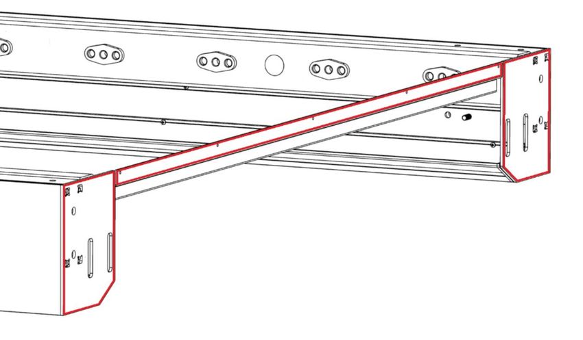
MEASUREMENT AND ASSEMBLY MANUAL

Variant B

Variant C

                                                                     2
Validity of the manual: 14. 10. 2020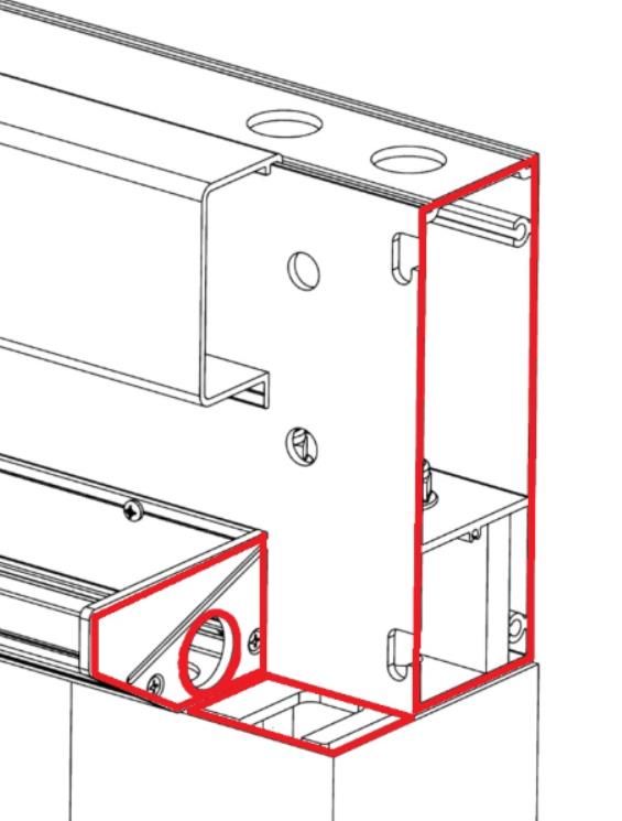
MEASUREMENT AND ASSEMBLY MANUAL
1. Introduction
READ THIS INSTALLATION MANUAL CAREFULLY PRIOR TO INSTALLING THE PERGOLA STRUCTURE. THIS
STRUCTURE HAS BEEN DESIGNED SOLELY AS PROTECTION FROM SUN, RAIN, AND WIND, AND CANNOT BE
CONSIDERED WATER-TIGHT.
INCORRECT USE OR INCORRECT INSTALLATION MAY RESULT IN THE TERMINATION OF THE GUARANTEE.
Anchoring materials must be selected with respect to the structure in which the pergola is to be attached. It
is necessary to consider various circumstances: texture and external insulation, rigidity, and surface
appearance.
2. LIST OF NECESSARY AND RECOMMENDED TOOLS
Two ladders adjustable according to the pergola height, telescopic lifting appliance, mobile scaffold;
Water level, tape measure, tool for measuring the wall’s right angle, flatness, and verticality, plumb line;
Socket-wrench set with 30 cm extension (socket 5.5 mm), spanners, Allen keys, hammer drill, drill set,
angle grinder + diamond-wheel for tiles;
Flat-blade screwdriver, T15 Torx screwdriver, vacuum cleaner;
Suitable sealing compound (polymer/polyurethane caulk, silicone), compression tape, bolts with packing
rubber.
3. INSTALLATION INSTRUCTIONS
Ground Mounting – Variant A
It is expected that for this variant, at least concrete feet have been prepared in advance, or a flat surface is
available to which the pergola is to be installed. The recommended minimum foot dimensions are 300 ×
300 mm, frostproof depth.
A.1 First determine plane A1–A3 (C1–C3) and feet placement positions.
If water outflow is located under the pole, start with this plane! The diagonal for the placement of the
remaining poles will be aligned to this plane. We recommend using a laser device or other technology for the
alignment. After aligning, place the feet to the ground and mark out their anchoring holes. Use a suitable
anchoring system to fasten the feet (e.g. threaded rod, chemical anchor) – we recommend stainless threaded
rods. Do not tighten the nuts on the threaded rods. The recommended total height of the threaded rods is
150 mm, thereof 30 mm above the anchoring plane.
If you want to have the anchoring prepared in advance, you can use a drill template for the feet openings
following the pergola placement measurements (see the last page of the manual, in full scale). We
recommend checking the template dimensions (110 mm), due to different print formats.
A.2 Insert the pole cover section and slide pole A1 to foot A1. Pay attention to placing the right pole to the
right place. If the motor supply cable passes through the pole, run it through a dedicated opening, see the
anchoring template. If the pole serves for water draining, insert the funnel and the plastic tube (40×1.8 mm)
for water draining (not part of delivery) into the pole and apply sealing compound to the funnel, see Fig.
D.1.
A.3 Adjust the height of the pole A1 according to the actual passage height (the pole height can be adjusted
3
Validity of the manual: 14. 10. 2020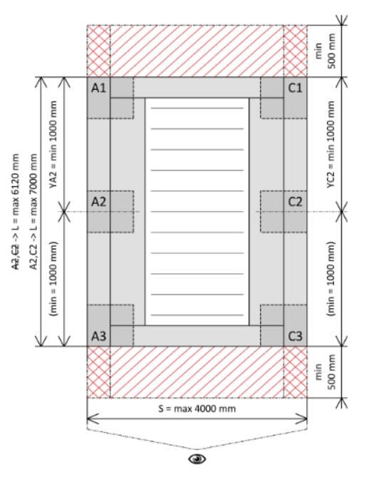
MEASUREMENT AND ASSEMBLY MANUAL

in the range of + 2 cm) and tighten the four countersunk bolts M8. When fitting the pole to the foot, the pole
is at the -2 cm position of the set height.
A.4 Repeat steps A.2 and A.3 for the remaining poles.
A.5 Insert the perimeter section A1A3 in the pre-installed pole A1 and pole A3. Do not hold the perimeter
section by the eaves part only – hold it by the main supporting section. Otherwise eaves will likely be
damaged.
If the pergola is placed under a roof or truss, it is necessary to allow for at least 380 mm above the pole
inserted in the foot for inserting the perimeter section.
A.6 Secure the connection of the perimeter section A1A3 and pole A1 by pre-installed bolts (4 countersunk
bolts M8 for each pole).
A.7 Secure the connection of the perimeter section A1A3 and pole A3 by pre-installed bolts (4 countersunk
bolts M8 for each pole).
A.8 Repeat steps A.5 through A.7 for the perimeter section C1C3 and pole C1 and pole C3.
A.9 Prior to installing the perimeter section A1C1, insert reinforcement to both sides of the section. Then
connect the section A1A3 and perimeter section C1C3. Prior to installing, apply sealing compound to the
side cover of the drainage channel, see Fig. D.2. Insert the perimeter section A1C1 between the pole A1 and
pole C1 so that the pre-installed 6HR screws fit in the grooves. Tighten the pre-installed 6HR screws on both
sides of the perimeter section A1C1.
A.10 Insert two cup-head bolts M10×20 to each corner of the frame and tighten.
A.11 Insert one hexagon-head bolt M10×340 to each corner and tighten. If the pergola is placed under a roof
or truss and the room above the pergola is not sufficient for inserting the bolts, do not use the bolts. This
does not affect the pergola function.
A.12 Repeat steps A.9 and A.10 for the perimeter section A3C3.
A.13 Check the dimensions of the diagonals, check the frame flatness and pole verticality, and adjust if
necessary.
A.14 If no problem is found, tighten the fastening nuts in the perimeter section, tighten the nuts in feet and
overlap the gap by the pole cover section. Attach the cover section to the pole (use bolts or silicone).
A.15 Insert the individual slats in the corresponding side sockets and secure with locks. The side sockets in
the perimeter section are adjusted to 45° slat tilting. The first slat and the last slat must be oriented with
respect to the limit sections attached to the perimeter sections A1C1 and A3C3.
A.16 Connect the motor and lighting, if any, and hide the cables inside the perimeter section and transverse
section.
A.17 If the pergola includes a LED lighting unit, connect it using connecting plugs.
A.18 Connect the LED lighting unit to the power supply unit using a cable with Hirschmann terminal.
A.19 Test the slat tilting function; the end-of-travel positions are factory-set. It is not possible to adjust the
limit section for opening, as this will likely lead to the slat mechanism collision.
A.20 Attach the side covers to the perimeter sections.

                                                                                                                     4
Validity of the manual: 14. 10. 2020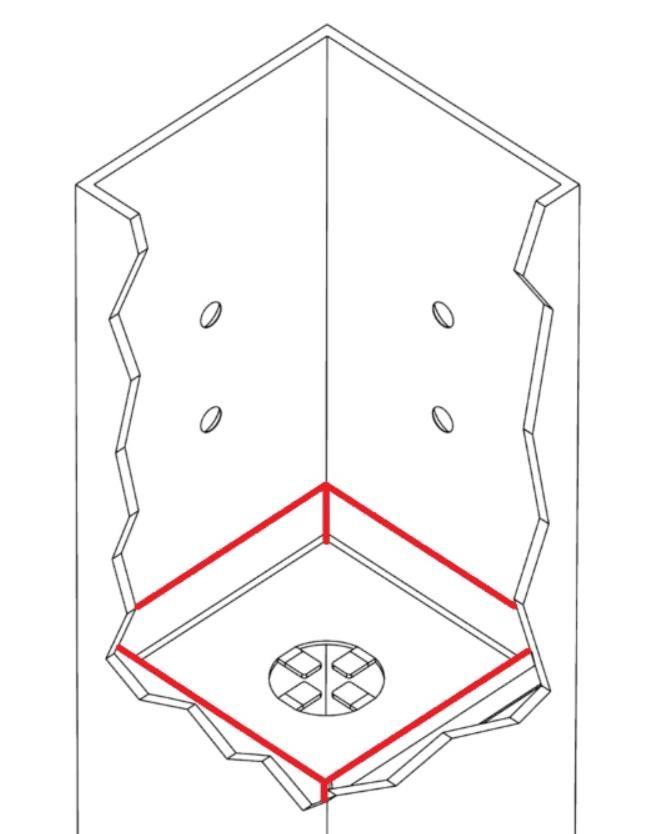
MEASUREMENT AND ASSEMBLY MANUAL

GROUND MOUNTING – VARIANT A – figures to illustrate the above activities

                                                                           5
Validity of the manual: 14. 10. 2020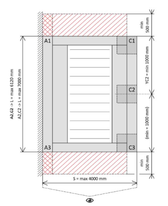
MEASUREMENT AND ASSEMBLY MANUAL

                                                                     6
Validity of the manual: 14. 10. 2020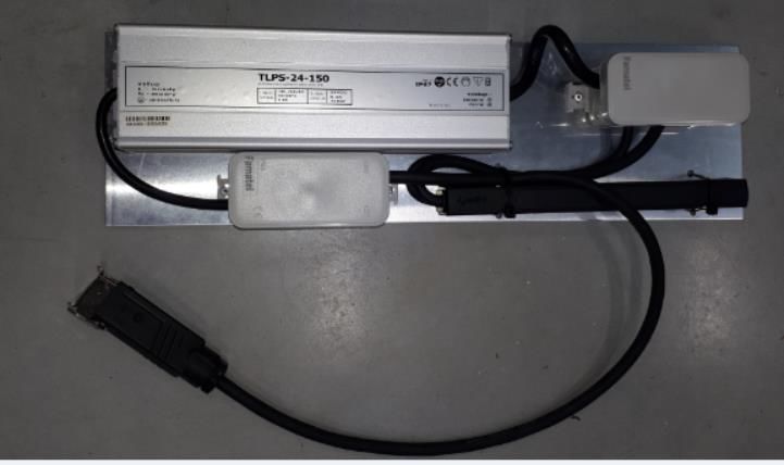
MEASUREMENT AND ASSEMBLY MANUAL

                                                                     7
Validity of the manual: 14. 10. 2020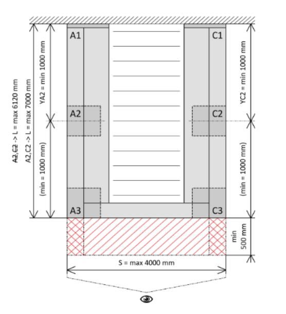
MEASUREMENT AND ASSEMBLY MANUAL

                                                                     8
Validity of the manual: 14. 10. 2020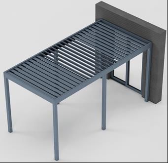
MEASUREMENT AND ASSEMBLY MANUAL

WALL MOUNTING – VARIANT B

Prior to taking any measurements, check the surface to which the pergola is to be installed. Measure the
surface inclination, difference of level at the house wall and on the opposite side of the pergola. Place the
pergola in accordance with the client’s instructions (to the centre, to the left side, etc.).

B.1 In locations A1 and C1 on the wall, mark out the places for the installation of the perimeter section
holders, based on the measure-taking. Take the measures by starting on one side and then indicating the
placement of the individual feet diagonally. Then indicate the anchoring holes. In doing so, pay special
attention to alignment and connection of the pergola poles to the water outflow. When taking
measurements of the openings for the attachment of locations A1 and C1 (their height from the surface),
take the surface inclination into account. This way you will ensure the same passage height on both sides of
the pergola and the flatness of the perimeter section.

B.2 Take measurements of the anchoring points for the installation of the pole A3 and pole C3.
Then proceed in accordance with items A.1 through A.4 above.

B.3 Insert the perimeter section A1A3 to the pre-installed pole A3 and press it against the wall mounting
point A1. Do not hold the perimeter section by the eaves part only – hold it by the main supporting section.
Otherwise eaves will likely be damaged. Prior to installing, apply sealing compound to the perimeter
section, see Fig. D.3.

B.4 Use a suitable anchoring system to fasten to attach the perimeter section A1A3 to the wall at A1. Pay
special attention to alignment and positioning during this operation.
Then proceed in accordance with items A.8 through A.14.

B.5 Measure the placement of the end section at the building wall with the last slat closed, so that the slat
fully shuts into the section. Install the end section and apply polymer- or polyurethane-based caulk (1) to its
rear and upper sides.

B.6 Measure the placement of the cover section (4) above the points A1-C1 of the pergola. Prior to installing,
apply compression tape (2) to its rear side. We recommend a 15 mm tape with the 5–15 mm compression.
Attach the cover section to the facade using bolts with packing rubber (3). Apply polymer- or polyurethane-
based caulk (1) to the upper edge of the cover section.
Then proceed in accordance with items A.15 through A.20

                                                                                                                9
Validity of the manual: 14. 10. 2020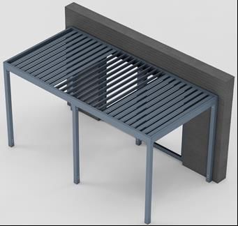
MEASUREMENT AND ASSEMBLY MANUAL

WALL MOUNTING – VARIANT B – figures to illustrate the above activities

B3 - detail

B5, B6

                                                                           10
Validity of the manual: 14. 10. 2020
MEASUREMENT AND ASSEMBLY MANUAL
B5, B6
11
Validity of the manual: 14. 10. 2020MEASUREMENT AND ASSEMBLY MANUAL
WALL MOUNTING – VARIANT C
Prior to taking any measurements, check the surface to which the pergola is to be installed. Measure the
surface inclination, difference of level at the house wall and on the opposite side of the pergola. Place the
pergola in accordance with the client’s instructions (to the centre, to the left side, etc.). Check the wall flatness
at the perimeter section installation area.
C.1 Indicate on the wall the position for the installation of the perimeter section A1A3, based on the measure-
taking. Take the measures by starting on one side and then indicating the placement of the individual feet
diagonally. In doing so, pay special attention to alignment and connection of the pergola poles to the water
outflow. When taking measurements of the openings for the attachment of locations A1 and C1 (their height
from the surface), take the surface inclination into account. This way you will ensure the same passage height
on both sides of the pergola and the flatness of the perimeter section.
C.2 Remove the eaves gutter from the perimeter section A1A3 (the gutter is not treated with sealing
compound at the lower side).
C.3 Drill the wall mounting holes to the space below the eaves (the quantity and spacing of the holes should
respect the material to which the pergola is to be anchored). The sections have already been predrilled – 3
holes of 28 mm diameter. Drill more holes if necessary.
C.4 Use a suitable anchoring system to attach the perimeter section A1A3 (e.g. M10 threaded rod, chemical
anchor). Apply polymer- or polyurethane-based caulk (1) to the upper edge of the perimeter section, see Fig.
C.6.
C.5 Attach the eaves gutter to the perimeter section A1A3. Do not forget to apply sealing compound to the
lower side!
Then proceed in accordance with items A.1 through A.14.
C.6 Attach the cover section (4) to the pergola perimeter section and to the wall. Apply compression tape (2)
to the cover section and attach the section to the perimeter section using Tex bolts with packing rubber (3).
Apply polymer- or polyurethane-based caulk (1) to the upper edge of the cover section (1).
Then proceed in accordance with items A.15 through A.20.
12
Validity of the manual: 14. 10. 2020MEASUREMENT AND ASSEMBLY MANUAL
WALL MOUNTING – VARIANT C – figures to illustrate the above activities
C3
13
Validity of the manual: 14. 10. 2020MEASUREMENT AND ASSEMBLY MANUAL
C6
14
Validity of the manual: 14. 10. 2020MEASUREMENT AND ASSEMBLY MANUAL
STRUCTURAL PARTS TO BE TREATED WITH SEALING COMPOUND
D.1 D.2
D.3
15
Validity of the manual: 14. 10. 2020MEASUREMENT AND ASSEMBLY MANUAL
ELECTRICAL CONNECTIONS
The pergolas are controlled by one, two, or three motors, and the individual sections can be controlled
individually, or together.
The standard configuration is Somfy io motor with Somfy Situo 5 Variation io controller. If a rain sensor is
used, it is necessary to use the WT motor with a remote control receiver (the rain sensor is not supplied in the
io version).
The central junction box is located in the section (A1-A3 or C1-C3) together with the motors and ensures 220
V power supply for the motors and LED lighting unit. The junction box can be removed if necessary (to pair up
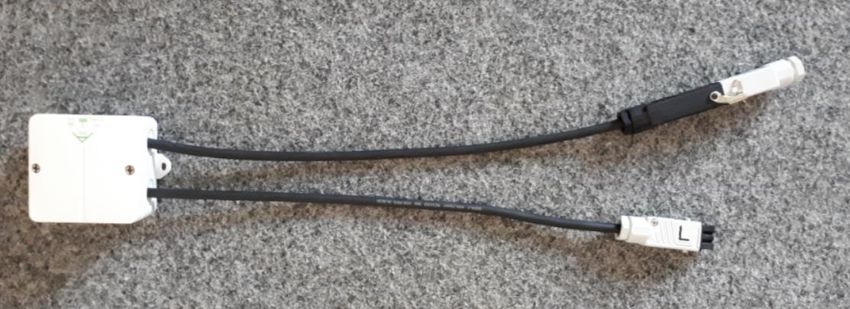
the individual motors with the controller). Two cables with Hirschmann terminals lead from the box – one for
the LED lighting unit, the other to connect the pergola to the input power.
Complete power supply of all electric parts of the pergola is therefore ensured by a single power supply cable
with a Hirschmann terminal. See below for the Hirschmann terminal connection.
Wiring of standard IO motor Wiring of WT motor
1 - Neutral wire (N) 1 modrá 2 černá 3 hnědá 4 žluto-zelená 1 - Neutral wire (N)
2 - Phase wire (L) 2 - Phase wire (up)
3 – Unused 3 - Phase wire (down)
4 - Protective wire (PE) PE - Protective wire
16
Validity of the manual: 14. 10. 2020MEASUREMENT AND ASSEMBLY MANUAL
The LED supply unit is placed within the transverse section (A1-C1 or A3-C3). The unit is powered from the
central box using a Hirschmann terminal.
The LED supply unit contains a 220/24 V transformer, LED io receiver, connecting box. The unit can be
removed from the transverse section.
It is possible to equip the pergolas with LED strip lighting – 24 V DC, warm white colour, CRI 90+. The LED
strips are integrated from below in the drainage channel, the strips are located on both longitudinal sides of the
pergola (A1-A3 and C1-C3).
The LED strips are powered using cables with screw connectors for fast connection.
THE ACTUAL EXECUTION OF THE INDIVIDUAL POWER SUPPLY UNITS MAY DIFFER ACCORDING TO
THE METHOD OF CONTROL, NUMBER OF MOTORS, AND INSTALLED TYPE OF LIGHTING!
MULTI-MOTOR PERGOLAS
Controls are carried out by Situo 5 Variation io controller (or other types of controllers).
If the pergola is supplied with a controller, the individual motors are paired up with the controller incl. lighting,
and they are set to the end positions of the motors (start and end position of the slats).
If the controller is not supplied, only the end positions of the motors are set. In such cases, the motors must be
paired up with the controller before the assembly. In doing so, it is necessary to remove the central power
supply box from the upper section, see fig. below, open the box and use the Wago clamps to leave only one
motor energised and pair the motor (only one motor may be energised in order to pair it with the controller).
DO NOT ALTER THE ADJUSTMENT OF END POSITIONS, AS THIS WILL LIKELY CAUSE THEIR
COLLISION AND DAMAGE!
17
Validity of the manual: 14. 10. 2020MEASUREMENT AND ASSEMBLY MANUAL
INSTALLATION OF SHADING TECHNOLOGY
We recommend installing the shading technology between the pergola poles, (installation to opening), using
the revealed installation method. Installation between the pergola pole and the building wall is more
complicated, as regards both measurement and assembly – attachment of guide rails to the wall. We do not
recommend anchoring the guide rails through the building’s external insulation. In such cases, it is advisable
to install the pergola pole near the wall and anchor the guide rails of the screen roller blind in this pole. When
installing our screen ZIP roller blinds, we recommend to always use guide rails type 838.
With respect to the dimensions of poles used for the Artosi pergolas (110 × 110 mm), we recommend using
110 mm box when installing screen roller blinds. If a larger box is used and the roller blinds are attached to the
pergola corner joints, the rear sides of the boxes will collide, and in such a case neither roller blind can be
installed so that it fits against the outer edge of the perimeter sections!
If the pergola is installed onto the building and the screen roller blinds are ordered together with the pergola,
we recommend measuring the inclination from the building during the initial measurement. The measured
values should then be considered in the order form to specify the accurate height of the screen roller blind
(difference in the length of the guide rails).
If shading technology (screen roller blinds) is to be installed later – after the supply of the pergola –, it is
necessary to carefully consider the installation of wiring. It is necessary to carefully choose the position of
drilled holes in order not to damage the water draining chambers. If the situation so requires, cables may also
be installed on the upper surface of the perimeter section.
UNPACKING AND STORING THE PERGOLA
IN MOST CASES, THE PERGOLA IS SUPPLIED IN WOODEN CRATES. WE THEREFORE RECOMMEND
UNLOADING THE CRATES FROM THE VEHICLE USING A FORK-LIFT TRUCK. IF A FORK-LIFT TRUCK
CANNOT BE PROVIDED, OPEN THE CRATES ON THE VEHICLE AND CAREFULLY UNLOAD THE
INDIVIDUAL PARTS OF THE PERGOLA AND PLACE THEM ON A FLAT SURFACE – CRATE COVER,
ETC. CHECK THE CRATES AND COMPONENTS INSIDE THEM FOR ANY DAMAGE CAUSED BY THE
TRANSPORT.
STORE THE PERGOLA IN THE ORIGINAL PACKAGING. IF NOT INSTALLED IMMEDIATELY AFTER
UNLOADING, STORE THE PERGOLA IN A DRY PLACE AND PROTECT IT FROM DIRECT SUNLIGHT.
BE CAREFUL WHEN UNPACKING THE PERGOLA, CHECK WHETHER ALL PARTS ARE INTACT, DO
NOT DAMAGE THE PAINTWORK. IN CASE OF ANY DEFECT, DOCUMENT THE DEFECT AND
CONTINUE THE ASSEMBLY ACCORDING TO THE MANUAL. ONLY SKIP PROCESSES WHERE SEALING
COMPOUND IS TO BE APPLIED! (This is due to possible replacement of defective parts, does not apply to
slats.)
RECOMMENDED MAINTENANCE:
• Apply a special treatment to the rubber sealing of the slats in the spring and before the winter;
• Remove branches and other large debris from the roofed-over areas;
• Regularly clean the drainage channels (remove leaves, etc.) to prevent their clogging;
18
Validity of the manual: 14. 10. 2020MEASUREMENT AND ASSEMBLY MANUAL
• Do clean the structural parts with aggressive cleaning products like organic solvents, cleaning pastes and
sands, and strong alkali cleaners;
• Turn the slats to 90° angle for the winter.
SAFETY INSTRUCTIONS:
• Do not block the slats when in motion, and in never insert your hands between the slats;
• If the pergola is equipped with shading technology, roll the blind up in adverse weather conditions;
• Do not let children play with the control devices;
• Regularly inspect the pergola for damage;
• If you identify damage or breakdown, contact your system’s supplier.
Due to continuous product refinement, technical information stated herein may not correspond to the actual
condition of the pergola.
19
Validity of the manual: 14. 10. 2020MEASUREMENT AND ASSEMBLY MANUAL
Pergola Anchoring Template:
Space for cable outlet
The through hole is always oriented to the exterior side of the pergola.
View of the foot from the inner side of the pergola.
20
Validity of the manual: 14. 10. 2020MEASUREMENT AND ASSEMBLY MANUAL
Template Typ B
Space for cable outlet
21
Validity of the manual: 14. 10. 2020MEASUREMENT AND ASSEMBLY MANUAL
Construction readiness
22
Validity of the manual: 14. 10. 2020MEASUREMENT AND ASSEMBLY MANUAL
23
Validity of the manual: 14. 10. 2020You can also read