Imaging the Cell Surface: Argon Sputtering to Expose Inner Cell Structures
←
→
Page content transcription
If your browser does not render page correctly, please read the page content below
MICROSCOPY RESEARCH AND TECHNIQUE 63:115–121 (2004)
Imaging the Cell Surface: Argon Sputtering to Expose
Inner Cell Structures
GELSOMINA DE STASIO,1* BRADLEY H. FRAZER,1,2 MARCO GIRASOLE,3 LISA M. WIESE,1
EWA K. KRASNOWSKA,4 GIULIA GRECO,4 ANNALUCIA SERAFINO,4 AND TIZIANA PARASASSI4
1
University of Wisconsin-Madison, Department of Physics and Synchrotron Radiation Center, Stoughton, Wisconsin 53589
2
Institute de Physique Appliquée, Ecole Polytechnique Fédérale de Lausanne, CH-1015 Lausanne, Switzerland
3
Istituto di Struttura della Materia, CNR, 00133 Roma, Italy
4
Istituto di Neurobiologia e Medicina Molecolare, Sezione di Medicina Molecolare, CNR, 00137 Roma, Italy
KEY WORDS subcellular structure and processes; organelles; X-ray microscopy; biomaterials
and biological interfaces
ABSTRACT Established microscopies such as Scanning Electron Microscopy (SEM) and more
recent developments such as Atomic Force Microscopy (AFM) and X-ray Photo-Electron Emission
spectroMicroscopy (X-PEEM) can only image the sample surface. We present an argon sputtering
method able to progressively expose inner cell structures without apparent damage. By varying the
sputtering time, the structure of cell cytoskeleton, vesicles, mitochondria, nuclear membrane, and
nucleoli can be imaged. We compared images obtained with confocal fluorescence microscopy,
transmission electron microscopy (TEM), SEM, and X-PEEM on similar samples after argon
sputtering, then confirmed the similarity of reference intracellular structures, including cytoskel-
eton fibers, cell-cell and cell-substrate adhesion structures, and secretory vesicles. We conclude that
the sputtering method is a new valuable tool for surface sensitive microscopies. Microsc. Res. Tech.
63:115–121, 2004. © 2004 Wiley-Liss, Inc.
INTRODUCTION Samples were kept and transported in desiccators,
Scanning Electron Microscopy (SEM), Atomic Force and handled only in a dry nitrogen glove box. They
Microscopy (AFM) and chemical and spectroscopic in- were transferred to the Spectromicroscope for PHoto-
vestigations by X-ray PhotoElectron Emission spec- electron Imaging of Nanostructures with X-rays
troMicroscopy (X-PEEM) can only image and analyze (SPHINX) (Frazer et al., 2003) X-PEEM ultra-high vac-
the sample surface. Therefore, inner cell organelles uum preparation chamber for sputtering. The base
such as the vesicular apparatus and mitochondria, or pressure in this chamber is 1 ⫻ 10⫺10 Torr. Sputtering
supramolecular assemblies such as the internal struc- was performed by leaking Ar gas into the chamber to a
ture of plasmalemma, cell-cell junctions, the cytoskel- constant pressure of 1.5 ⫻ 10⫺5 Torr, with an ion gun
eton, and the nuclear membrane cannot be visualized. (SPECS model IQE 11/35) at 3 kV, mounted at a dis-
We present here a novel method suited to expose inner tance of approximately 40 cm from the sample surface.
structures in whole fixed cells by argon sputtering their Argon sputtering of the cells was performed for 0 –15
top-most portion, making these structures available for minutes depending on the desired cell structure to be
surface-sensitive techniques. By varying the sputter- exposed. After sputtering, the cells were sputter-coated
ing time, structures located at different depths can be with 200 Å gold for SEM analysis, and with 10 Å Pt/Pd
exposed and imaged. We compared SEM and X-PEEM for SPHINX analysis.
images with those obtained on similar cells using con- Scanning electron microscopy observation was car-
focal fluorescence microscopy and TEM. ried out using the Stereoscan 240 scanning electron
microscope (Cambridge Instr., Cambridge, UK).
MATERIALS AND METHODS SPHINX spectromicroscopy analysis was performed
at the Wisconsin Synchrotron Radiation Center (SRC).
The Caco-2 human colon carcinoma cells (Mahraoui SPHINX is an X-PEEM, described in detail in Frazer et
et al., 1994) were plated at a density of 20 ⫻ 103 al. (2003), and mounted on the undulator PGM beam-
cells/cm2, grown in Dulbecco’s modified Eagle mini- line (12–240 eV photon energy) or on the HERMON
mum essential medium (DMEM, GIBCO Labs, Grand beamline (62–1,200 eV).
Island, NY), supplemented with 10% (v/v) heat-inacti-
vated fetal calf serum (GIBCO Labs), L-glutamine
(2 mM), penicillin (50 IU/ml), and streptomycin
(50 g/ml). Cells were plated and allowed to grow for *Correspondence to: Gelsomina De Stasio, University of Wisconsin-Madison,
Synchrotron Radiation Center, 3731 Schneider Drive, Stoughton WI
1 to 3 days on 10 ⫻ 10 mm silicon wafers, followed by 53589. E-mail: pupa@src.wisc.edu
fixing with 2.5% glutharaldehyde in 0.1 M Millonig’s Received 1 August 2003; accepted in revised form 15 October 2003
phosphate buffer (MPB) at 4°C for 1 hour. After wash- Contract grant sponsor: CNR; Contract grant sponsor: University Wisconsin
(Graduate School, Physics Department, Technology Innovation Fund-University
ing in MPB, cells were dehydrated in increasing ace- Industry Relations, and the Comprehensive Cancer Center).
tone concentrations and then critical-point dried using DOI 10.1002/jemt.20019
liquid CO2. Published online in Wiley InterScience (www.interscience.wiley.com).
© 2004 WILEY-LISS, INC.Fig. 1. Scanning electron micrographs of unsputtered Caco-2 cells. A: Numerous villous structures
are present on cell surface in a non-confluent monolayer; B: Cell-cell contacts are shown (arrowheads);
C: In differentiated cells, brush border microvilli are present at the apical pole (double-pointed arrows).
Bars ⫽ 10 m.
Fig. 2. Scanning electron micrographs of Caco-2 cells after 1, 2, cytoplasmic structures, such as cisternae of endoplasmic reticulum
and 3 minutes sputtering. A–H: After 1 and 2 minutes sputtering, the (arrowheads) and nuclear envelope (double-pointed arrows), become
cell appearance is very similar to unsputtered controls; arrows point visible only in flat cells (K and J). n: nucleus. Bars ⫽ 10 m.
to cell-cell junction. I–L: After 3 minutes sputtering, some innerSURFACE MICROSCOPY OF INTRACELLULAR STRUCTURE 117 Fig. 3. Scanning electron micrographs of Caco-2 cells after 8, 10, vesicles (arrows) and nucleoli (asterisks) are completely exposed (E, and 15 minutes sputtering. A–D: After 8 minutes sputtering, the F) as well as cytoskeleton fibers (G, H); in H, arrowheads point to exposure of endoplasmic reticulum in flat cells is more evident (A, B); cell-cell junction. I–L: After 15 minutes, the cytoskeletal network at some cytoplasmic organelles (arrows) and cytoskeletal structures be- cell-cell junction (arrowheads in I–K) and at the cell-substrate adhe- come visible beneath the cell surface of thick differentiated cells (C, sion site (arrowheads in I–K), as well as secretory vesicles (open D). E–H: After 10 minutes sputtering, cytoplasmic organelles and arrows in L), are well visible. n: nucleus. Bars ⫽ 10 m. For immunofluorescence labeling and confocal laser to human vinculin (Sigma Chem. Co), revealed by tetra- scanning microscopy observations, Caco-2 cells grown on methylrhodamine-isothiocyanate (TRITC)-conjugated anti- coverslips were washed with phosphate buffer saline mouse IgG. For Golgi apparatus and endoplasmic re- (PBS), fixed with 4% paraformaldehyde for 10 minutes, ticulum staining, cells were incubated with TRITC- permeabilized with 0.2% Triton-X 100 in PBS for conjugated wheat germ agglutinin (WGA-TRITC; 5 minutes, and then labeled with fluorescent staining. Sigma) for 1 hour at room temperature. Fluorescently Actin microfilaments were stained with fluorescein labeled samples were imaged by a confocal LEICA TCS (FITC)-conjugated phalloidin (Sigma Chem. Co., St 4D microscope (Leica, Heidelberg, Germany) equipped Louis, MO). Cell-substrate plaques were labeled by mAbs with an argon/kripton laser and 40 ⫻ 1.00 – 0.5 or 100 ⫻
118 G. DE STASIO ET AL. Fig. 4. Scanning electron micrographs of Caco-2 cells after secretory vesicles (double-pointed arrows). H–L: Details of exposed 15 minutes sputtering. A, B: Details of cytoskeleton fibers at cell-cell cytoskeletal network in thick differentiated cells; arrows in I) point to junction (arrows). C–E: Details of cytoskeleton fibers at the cell- cell-cell junction; in K and L, cytoplasmic organelles connected to substrate adhesion site (open arrows); in E, arrowheads point to thick cytoskeleton fibers are shown (asterisks). Bars ⫽ 10 m. packed fibers. F,G: Details of exposed cytoplasmic organelles and 1.3– 0.6 oil immersion lenses. The excitation and emission anol concentrations and embedded in Spurr epoxy wavelengths employed were 488 and 510 nm, for FITC- resin (Agar Scientific LTD, Stansted, Essex, UK). Ul- labeling, and 568 and 590 nm, for TRITC-labeling. The trathin sections were stained with uranyl acetate and images were recorded by pseudo-color representation. lead citrate, then observed by a Philips CM12 trans- For TEM observations, cells were fixed for 1 hour at mission electron microscope operating at 80 kV. 4°C with 2.5% glutharaldheyde in 0.1 M Millonig’s phosphate buffer (MPB) containing 2% sucrose, and RESULTS AND DISCUSSION post-fixed for 1 hour at 4°C with 1% OsO4 in the same SEM images of un-sputtered Caco-2 cells are shown buffer. Specimens were dehydrated in increasing eth- in Figure 1. Their characteristic microvillar structure
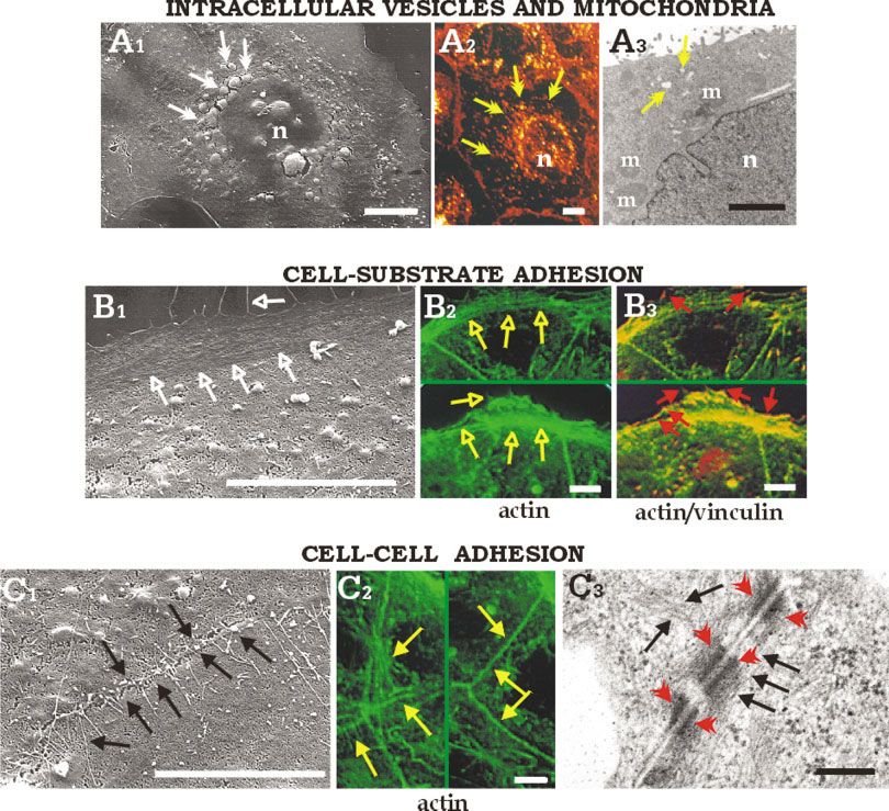
SURFACE MICROSCOPY OF INTRACELLULAR STRUCTURE 119 Fig. 5. Scanning electron micrographs of Caco-2 cells after in detail, in B2 the actin fiber-deriving signal (green) is reported, while 15 minutes sputtering (A1, B1, C1) compared with images obtained by in B3, the double staining actin (green)/vinculin (red) is shown, with confocal microscopy (CLSM, A2, B2, B3, C2) on whole cells and trans- the yellow hue indicating the colocalization of the two fluorescent mission electron microscopy (TEM, A3, C3) on ultrathin sections. A: signals. C: Exposure of microfilament network at the cell-cell adhe- Exposure of intracellular organelles (white arrows) similar in size and sion structures similar in distribution to actin fibers observed by distribution to WGA-stained vesicles (yellow arrows) and mitochon- CLSM (yellow arrows, C2) or by TEM (black arrows, C3) at the cell-cell dria (m) observed by CLSM (A2) or TEM (A3). B: Exposure of micro- junctions (red arrowheads). Bars ⫽ 10 m, except in A3 (2 m) and C3 filament network at the cell-substrate adhesion site (open white ar- (200 nm). [Color figure can be viewed in the online issue, which is rows) similar in distribution to actin fibers (open yellow arrows) and available at www.interscience.wiley.com.] substrate adhesion plaques (red arrows) observed by CLSM (B2, B3); is evident. Figures 2– 4 show SEM images of the cell In Figure 5, we show a comparison of the SEM mi- surface appearance revealed by increasing the sputter- crographs of intracellular structures exposed after ing times up to 15 minutes. At very short times (Fig, 15 minutes sputtering with images obtained by conven- 2A–H) the cell appearance is very similar to un-sput- tional microscopies, including confocal fluorescence mi- tered control cells (Fig. 1), while by increasing the croscopy and TEM. In particular, in Figure 5A1 intra- sputtering time, several inner cytoplasmic structures cellular organelles are exposed, similar in size and become visible, such as endoplasmic reticulum, nuclear distribution to: (1) the secretory vesicles specifically membrane and nucleoli, cytoplasmic organelles, secre- labeled and observed by confocal microscopy (Fig. 5A2), tory vesicles, and cytoskeleton fibers. and (2) the mitochondria, as visualized by TEM (Fig.
120 G. DE STASIO ET AL.
Fig. 6. SPHINX images of Caco-2 cells after 15 minutes sputtering compared to SEM images. Actin
microfilament network at cell-substrate (A, C, E) and cell-cell (B, D, F) adhesion sites and exposed
cytoplasmic vesicles (white arrows) imaged by SPHINX (A–D) and SEM (E, F). Bars ⫽ 5 m.SURFACE MICROSCOPY OF INTRACELLULAR STRUCTURE 121
5A3). Actin fibers at the cell-substrate adhesion sites, organelles of eukaryotic cells. The sputtering efficacy
imaged after 15 minutes sputtering are shown in Fig- in exposing inner cell structures was evaluated by com-
ure 5B1 and compared with confocal microscopy images paring SPHINX images with TEM, SEM, and confocal
of specifically labeled actin microfilaments (Fig. 5B2), fluorescence microscopy images, acquired on similar
and of vinculin, a cytoskeletal component of substrate parallel samples. The size and distribution of the fibers
adhesion plaques (Fig. 5B3). A sputtering time of and intracellular vesicles are consistent in all used
15 minutes served also to expose actin fibers involved microscopy approaches. With this new sputtering
in the formation of cell-cell adhesion structures (Fig. method, future studies on the elemental composition
5C1), as easily identifiable for comparison with the and the oxidation state of elements in the cytoskeleton
confocal (Fig. 5C2) and TEM (Fig. 5C3) images. are made possible.
The SPHINX images of Caco-2 cells after 15 minutes
sputtering are shown in Figure 6A–D and compared to ACKNOWLEDGMENTS
the images obtained by SEM (Fig. 6E and F). This
sputtering time was sufficient to expose several fibers The sputtering and SPHINX experiments were
of the microfilament network at the cell-substrate ad- performed at the Synchrotron Radiation Center, Uni-
hesion sites, as well as some intracytoplasmic vesicles versity of Wisconsin-Madison, which is supported by
(double-pointed arrows). the NSF under Award No. DMR-0084402. The cell
As measured in the SPHINX and SEM micrographs, cultures, SEM, TEM, and confocal microscopy imag-
the cell-cell fibers range between 0.1– 0.4 m in diameter, ing, were done at the Istituto di Neurobiologia e
while cell-substrate fibers range between 0.2– 0.3 m. Medicina Molecolare, CNR, supported by Nactilus
The cell-cell adhesion fibers are 0.26 ⫾ 0.09 m AB, Malmö, Sweden. M.G. acknowledges a CNR
(mean ⫾ standard deviation) before sputtering and “short-term mobility” fellowship. G.D.S. acknowl-
0.22 ⫾ 0.043 m after sputtering (Student t ⫽ ⫺0.08, edges the support of the University of Wisconsin:
not significant), while the cell-substrate fibers are Graduate School, Physics Department, Technology
0.28 ⫾ 0.04 m in diameter before sputtering and Innovation Fund-University Industry Relations, and
0.14 ⫾ 0.026 m after sputtering (t ⫽ 5.23, highly Comprehensive Cancer Center.
significant). Since the cell-substrate adhesion fibers are
significantly thinner than the ones observed on the REFERENCES
unsputtered cells, we infer that after sputtering we Frazer BH, Girasole M, Wiese LM, Franz T, De Stasio G. 2003.
observe exposed naked actin fibers, while membranes, Spectromicroscope for the PHotoelectron Imaging of Nanostruc-
membrane proteins, and possibly parts of the fibers tures with X-rays (SPHINX): performance in biology, medicine and
themselves have been removed. geology, Ultramicroscopy (in press).
Mahraoui L, Rodolosse A, Barbat A, Dussaulx E, Zweibaum A, Rous-
CONCLUSIONS set M, Brot-Laroche E. 1994. Presence and differential expression of
SGLT1, GLUT1, GLUT2, GLUT3 and GLUT5 hexose-transporter
We presented the first tests of a cell-sputtering ap- mRNAs in Caco-2 cell clones in relation to cell growth and glucose
proach to reveal the cytoskeleton and intracytoplasmic consumption. Biochem J 298:629 – 633.You can also read