PHYSICAL REVIEW X 12, 021031 (2022) - Quantum Anomalous Hall Effect from Inverted Charge Transfer Gap
←
→
Page content transcription
If your browser does not render page correctly, please read the page content below

PHYSICAL REVIEW X 12, 021031 (2022)

                 Quantum Anomalous Hall Effect from Inverted Charge Transfer Gap
                                                 Trithep Devakul       and Liang Fu
              Department of Physics, Massachusetts Institute of Technology, Cambridge, Massachusetts 02139, USA

                (Received 3 November 2021; revised 24 January 2022; accepted 9 March 2022; published 6 May 2022)

                 A general mechanism is presented by which topological physics arises in strongly correlated systems
              without flat bands. Starting from a charge transfer insulator, topology emerges when the charge transfer
              energy between the cation and anion is reduced to invert the lower Hubbard band and the spin-degenerate
              charge transfer band. A universal low-energy theory is developed for the inversion of the charge transfer
              gap in a quantum antiferromagnet. The inverted state is found to be a quantum anomalous Hall (QAH)
              insulator with noncoplanar magnetism. Interactions play two essential roles in this mechanism: producing
              the insulating gap and quasiparticle bands prior to the band inversion, and causing the change of magnetic
              order necessary for the QAH effect after inversion. Our theory explains the electric-field-induced transition
              from a correlated insulator to a QAH state in AB-stacked transition-metal-dichalcogenides bilayer
              MoTe2 =WSe2 .
              DOI: 10.1103/PhysRevX.12.021031                          Subject Areas: Condensed Matter Physics
                                                                                      Strongly Correlated Materials

   Electron correlation and band topology are two pivotal             we find a simple and natural mechanism leading to
themes of quantum matter theory, which are deeply rooted              magnetic topological insulators that exhibit noncollinear
in the particle and wave aspect of electrons, respectively.           spin structures and a quantum anomalous Hall effect.
The opposing traits of correlation and topology are clearly              For systems with an odd number of electrons per unit
displayed in the contrast between a Mott insulator [1] and a          cell, a large enough Coulomb repulsion U can suppress
Chern insulator [2]. In a Mott insulator, electrons are bound         double occupancy and produce an insulating state. In one-
to individual atoms, and their motion is inhibited by mutual          band Hubbard models at large U, the single-particle
Coulomb repulsion. In contrast, a Chern insulator features            spectral function consists of the lower and upper
chiral electrons on the boundary that refuse to localize.             Hubbard bands separated by the Mott gap [13]. More
Despite their differences, electron correlation and band              interesting and relevant to our work are charge-transfer
topology can cooperate to create fascinating states of                insulators [14–16] (such as the cuprate). These materials
matter, as exemplified by quantum Hall systems. More                  are comprised of cations (Cu) and anions (O). Transferring
recently, the scope of topology has been greatly expanded             an electron between the anion and the cation without
by the discovery of topological band insulators [3,4] in              creating double occupancy costs energy less than U. The
numerous semiconductor materials [5–8]. Since then, there             physics of charge transfer insulators is captured by two-
has been great interest in interaction-induced topological            band Hubbard models, where the band derived from anions
states in correlated electron systems such as transition metal        is located inside the Mott gap of the cation states. The
oxides and f-electron materials [9–12]. However, after                insulating gap is thus controlled by the charge transfer
considerable effort, it remains unclear whether there is a            energy Δ rather than U.
common mechanism for topological physics in generic                      The essence of our idea is that reducing the charge
Hubbard-type systems.                                                 transfer energy Δ can induce band inversion between cation
   This work is an attempt to provide a guiding principle for         and anion Hubbard bands and thereby drive a transition
the realization of strongly correlated topological states in          from a Mott insulator to a topologically nontrivial state in
materials with an odd number of electrons per unit cell.              which cations and anions are highly entangled. The
Building on and linking together the notions of Hubbard               insulating state that emerges after this transition can be
band, charge transfer gap, and topological band inversion,            viewed as having a negative charge transfer gap, in analogy
                                                                      with a negative band gap in inverted semiconductors [17].
                                                                         The band inversion paradigm is remarkably successful in
Published by the American Physical Society under the terms of         understanding and predicting topological band insulators
the Creative Commons Attribution 4.0 International license.
Further distribution of this work must maintain attribution to        [5,18–22]. A prime example is SnTe, in which the cation Sn
the author(s) and the published article’s title, journal citation,    band and anion Te band are inverted around the L points in
and DOI.                                                              the Brillouin zone [21]. The crucial difference here is that

2160-3308=22=12(2)=021031(14)                                  021031-1               Published by the American Physical Society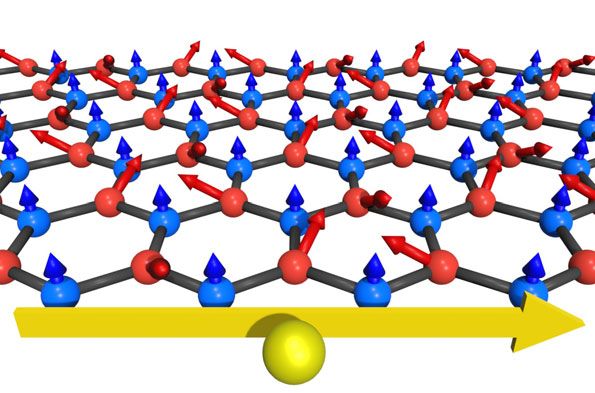
TRITHEP DEVAKUL and LIANG FU                                                                          PHYS. REV. X 12, 021031 (2022)
                                                                                                             X            X
                                                                       H ¼ HA þ HB þ HAB þ UA                 ni↑ ni↓ þ UB ni↑ ni↓ :
                                                                                                              i∈A                      i∈B

                                                                                                                                                    ð1Þ

                                                                       Unless stated otherwise, we take U A ¼ UB ¼ U. Here, HA
                                                                       and HB are the tight-binding Hamiltonians within each
                                                                       sublattice, while HAB is the hybridization term:

                                                                                 X                                               X τα Δ
                                                                        Hα ¼ −              ðtα eisσ νij ϕα c†iσ cjσ þ H:c:Þ −               ni ;
                                                                                hi;jiα ;σ                                        i∈α
                                                                                                                                         2
                                                                                      X
                                                                       HAB ¼ −tAB              c†iσ cjσ ;                                           ð2Þ
                                                                                     hi;ji;σ

                                                                       where α ¼ A, B denotes the two sublattices; σ ¼↑; ↓
                                                                       electron spin Sz ; s↑ ¼ −s↓ ≡ 1; τA ¼ −τB ≡ 1. The first
                                                                       sum is over next-nearest-neighbor sites hi; jiα , which
FIG. 1. Illustration of our mechanism for topological Hubbard
band inversion. In the top panels, we start with a charge transfer
                                                                       belong to the same sublattice α. Here, the hopping
insulator with 120° xy AFM order on the A (red) sublattice. The A      amplitude can be complex and spin-sz dependent, describ-
quasiparticle band is split into a filled lower Hubbard band and an    ing an Ising spin-orbit coupling that is allowed by sym-
upper Hubbard band separated by energy U. The spin-degenerate          metry, with νij ¼ −νji ¼ 1 depending on the path
B band lies in the Hubbard gap, resulting in a charge transfer         connecting site j to i [34]. If the path turns right,
insulator with charge transfer energy Δ. In the bottom panels,         νij ¼ 1; otherwise, νij ¼ −1. The special case ϕA ¼ ϕB ¼
when Δ is reduced, a topological band inversion occurs. The            ðπ=2Þ corresponds to the original Kane-Mele model. The
Hubbard interaction on the B (blue) sublattice results in spin
                                                                       second term is a sublattice potential, with Δ the charge
splitting of the B bands and noncoplanar spin order, as illustrated.
The filled band has nontrivial Chern number and exhibits QAH.
                                                                       transfer energy. The last term is a hybridization term that
                                                                       connects nearest-neighbor sites hi; ji.
                                                                          Our model is motivated by and captures the essential
we consider correlated insulators with a many-body gap at              physics of K-valley spin-polarized moiré bands in tran-
half-filling. The quasiparticle bands that emerge in such              sition-metal-dichalcogenides (TMD) bilayers. Consider,
insulators generally bear no resemblance to the band struc-            for example, MoTe2 =WSe2 . Its low-energy electron states
ture in the noninteracting limit. Specifically, we show that the       reside primarily in the MM region of the MoTe2 layer and
inversion of cation and anion Hubbard bands in an anti-                the XX region of the WSe2 layer, respectively, which
ferromagnetic (AFM) charge transfer insulator leads to a               together form a honeycomb lattice [Fig. 5(b)] [33]. The
Chern insulator with canted AFM order, as shown schemati-              corresponding moiré bands are well described by our tight-
cally in Fig. 1. In order for this mechanism to work, certain          binding Hamiltonian H ¼ H A þ HB þ HAB , with the sub-
conditions regarding the Hubbard band structure and the                lattice and spin σ corresponding to the layer and the K
cation-anion hybridization must be satisfied.                          valley, respectively. The charge transfer energy Δ
   In bulk materials, the charge transfer energy Δ is largely          corresponds to the layer bias potential, which is tuned
determined by the chemistry of the underlying cation and               by an applied displacement field. As we show in
anion. Recently, moiré superlattices in semiconductor                 Appendix B, the relevant model parameters are ϕA ≈ 0
heterostructures [23–28] offered a physical realization of             and ϕB ≈ −½ð2πÞ=3. We focus on the case of ϕA ¼ 0 in our
charge transfer insulators [29–31], where Δ is highly                  following analysis.
tunable by the displacement field. Remarkably, a displace-                At Δ → ∞, our model effectively reduces to the standard
ment-field-induced transition from a correlated insulator to           one-band Hubbard model on the triangular lattice of A sites.
a quantum anomalous Hall (QAH) state has been discov-                  As is well known, at the filling n ¼ 1 considered through-
ered in AB-stacked MoTe2 =WSe2 heterostructures [32,33].               out this work, the ground state at large U is a 120° AFM
However, the origin and nature of this QAH state is not                ordered Mott insulator. For large (but finite) Δ, integrating
understood. Our theory explains the origin of this observed            out the B sublattice gives an effective A sublattice Hubbard
phenomenon and makes testable predictions.                             model with complex sz -dependent hopping parameters.
   To illustrate the emergence of topology from inverted               Consequently, the effective spin model derived from our
Hubbard bands, we introduce a two-band Hubbard model                   Hubbard model at large U is an XXZ Heisenberg model
of spin-12 electrons on the honeycomb lattice, with the A and          with a Dzyaloshinskii-Moriya interaction. The reduced
B sublattice representing the cation and anion, respectively:          spin Uð1Þ symmetry results in the 120° AFM within the

                                                                021031-2
QUANTUM ANOMALOUS HALL EFFECT FROM INVERTED …                                                         PHYS. REV. X 12, 021031 (2022)

xy plane, as shown in Ref. [35]. This AFM insulator serves                     (a)                                            (c)
as the starting point of our analysis below.
   In order to obtain the complete phase diagram of our
model, we perform a Hartree-Fock (HF) treatment of the
Hubbard interaction. We expect the HF treatment to give
qualitatively reasonable results for insulating phases, and
more importantly, it will allow for an analytical under-
standing of the key physics through the quasiparticle band                     (b)                                      (d)
structure. Our main findings from the HF study are fully
supported by density matrix renormalization group
(DMRG) calculations, to be presented below.
   The HF approximation amounts to the replacement of
the Hubbard term by

         UX                             1        1
 Hub ¼
HHF           ni hni i − ⃗si · h ⃗si i − hni i2 þ jh ⃗si ij2 ;   ð3Þ
         2 i                            2        2                     FIG. 2. (a) Order parameters and (b) charge gap obtained from
             P                                                         the self-consistent HF Hamiltonian as a function of Δ, for
where ni ¼ σ niσ , ski ¼ hc†iσ πkσσ 0 ciσ 0 i, and πk are k ¼ x, y,    parameters tA ¼ tB ¼ 12 tAB ¼ t, ϕA ¼ 0, ϕB ¼ −½ð2πÞ=3, and
z Pauli matrices. The HF Hamiltonian must be solved self-              U ¼ 50t. There is a transition from the xy AFM phase to the
consistently at the filling n ¼ 1 to obtain the HF ground              noncoplanar QAH phase with Chern number jCj ¼ 1 as Δ is
state (in cases where multiple self-consistent solutions are           reduced. The gap is also shown for U ¼ 30t. (c) Quasiparticle
found, the lowest energy solution among them is chosen).               band structure, with shift ζ ¼ −, obtained from the HF Hamil-
                                                                       tonian at Δ ¼ 7t. (d) Berry curvature of the filled topological band.
   In order to characterize the magnetic order, we define the
following order parameter, a matrix in spin space:
                                                                                                     P
                                                                       takes the form H0 ¼ kσ c⃗ †σk Hσ ðkÞ⃗cσk , where c⃗ †σk ¼
                           1X †
                 Sαζ     ≡    hc 0      c i;                     ð4Þ   ðc†Aσk ; c†Bσk ÞT in k space, and the Bloch Hamiltonian is
                  σ0 σ
                           N k ασ ðkþζKÞ ασk

                                                                                                          E Aσ ðkÞ   T σ ðkÞ
where ζ ¼ 0 describes ferromagnetic (FM) states and                                       H σ ðkÞ ¼                              ;      ð5Þ
ζ ¼ 1 describes AFM states with wave vector K ¼                                                         T †σ ðkÞ   E Bσ ðkÞ
½ð4πÞ=3að1; 0Þ. In the presence of a spin-orbit interaction,
                                                                       where
xy AFM states with ζ ¼ þ and − are distinct states
displaying spin configurations of opposite chirality, and                                        X                              1
they are not degenerate [36]. For ϕA ¼ 0 and ϕB ≈                           E ασ ðkÞ ¼ −2tα            cosðk · an þ sσ τα ϕα Þ − τα Δ; ð6Þ
                                                                                                                                2
−½ð2πÞ=3, the AFM Mott insulator at large Δ has ζ ¼ −1.                                          n
   The order parameters are shown in Fig. 2(a) as a function
of Δ near the band inversion point for ϕB ¼ −½ð2πÞ=3,                               T σ ðkÞ ¼ −tAB ðe−ik·b1 þ e−ik·b2 þ e−ik·b3 Þ;     ð7Þ
tA ¼ tB ¼ 12 tAB ¼ t, and U ¼ 50t. We have defined the
combinations Zα ≡ 12 ðSα0        α0                         αðζ¼−1Þ    wherepffiffiffi an ¼ afcos½ð2πnÞ=3; sin½ð2πnÞ=3g and bn ¼
                          ↑↑ − S↓↓ Þ and XYα ≡ jS↑↓            j,
                                                                       ða= 3Þfsin½ð2πnÞ=3; − cos½ð2πnÞ=3g.
which capture the observed nonzero z FM and xy AFM                        At large U, the quasiparticle band structure of the xy or
orders, respectively, on the α sublattice. Figure 2(b) also            canted AFM insulator is completely different frompffiffithe
shows the charge gap and Chern number of the HF ground                                                                             ffi
                                                                       noninteracting
                                                                       pffiffiffi            case. While  the AFM   order results in a  3  ×
state. We observe two distinct insulating phases: an xy
AFM (with ζ ¼ −) on the A sublattice at large Δ transitions               3 enlarged unit cell, this state is invariant under a
into a canted xy AFM as Δ is decreased. This canted phase,             combination of the unit translation and spin rotation around
in particular, has nontrivial Chern number jCj ¼ 1 and is              the z axis. Thanks to this symmetry property, the description
therefore a QAH phase. This QAH phase with noncoplanar                 of quasiparticle band structures can be simplified by perform-
magnetism appearing at reduced charge transfer energy Δ                ing a spin-dependent momentum boost with a unitary
is the highlight of this work.                                         transformation Uζ ∶c†↑k → c†↑ðkþζKÞ ; c†↓k → c†↓ðk−ζKÞ . This
   To gain insight into the origin of the QAH phase, we exa-           transformation preserves the z FM order and maps the xy
mine the evolution of the quasiparticle band structure as a            AFM order into xy FM order, which is translationally
function of Δ. As a first step, it is useful to first derive the       invariant. After this transformation, the HF Hamiltonian,
noninteracting band structure at U ¼ 0. By Fourier transfor-           which includes the effect of magnetic order, is a 4 × 4 matrix
mation, the single-particle Hamiltonian H0 ¼HA þH B þHAB               (involving the sublattice and spin) given by

                                                                 021031-3
TRITHEP DEVAKUL and LIANG FU                                                                         PHYS. REV. X 12, 021031 (2022)

                 H ðk − ζKÞ þ U S0                − 12 USζ↑↓            where k ≡ kx  iky . By projecting the HF Hamiltonian
                   ↑           2 ↓↓
 ζ ðkÞ ¼
HHF                                                                   ;   into this low-energy subspace, we obtain a k · p theory of
                       − 12 UðSζ↑↓ Þ        H↓ ðk þ ζKÞ þ U2 S0↑↑        quasiparticle band structure in the xy AFM state prior to
                                                                 ð8Þ      gap inversion:
                                                                                            0       k2                            1
                                                                                                 − 2m        λk−       −λeiθ kþ
where  Sζσ 0 σ
            ¼            σ 0 σ ; Sσ 0 σ Þ.
                   diagðSAζ       Bζ
                                                                                                      A
                                                                                          B                                       C
  In the limit Δ → ∞, the two sublattices are decoupled                       H eff ðkÞ ¼ B
                                                                                          @       λkþ        k2
                                                                                                            2mB   þδ         0    C;
                                                                                                                                  A    ð11Þ
and only the A sublattice is occupied at the filling of n ¼ 1,                                                          k2
thus realizing the triangular-lattice Hubbard model. In the                                     −λe−iθ k−         0    2mB   þδ
xy AFM insulator, the half-filled band splits into lower and
upper Hubbard bands Eζ ðkÞ, separated by the Mott gap U.                 with mA ¼ ½2=ð3tA a2 Þ in the large U limit, mB ¼ ½1=
In the large-U limit, the lower Hubbard band associated                   ð3tB a2 Þ, and where eiθ reflects the direction of in-plane
with hole excitations has the energy dispersion                           order on the A sublattice and δ defines the charge trans-
                                                                          fer gap.
                   1                                                         As the charge transfer gap δ is decreased and eventually
          Eζ− ðkÞ ¼ ½E A↑ ðk − ζKÞ þ E A↓ ðk þ ζKÞ:             ð9Þ      becomes negative (while the charge transfer energy Δ
                   2
                                                                          remains positive), the occupation of B sublattices increases;
Since the hopping amplitude of holes between adjacent                     hence, the effect of Hubbard repulsion U B between
sites is effectively reduced by the noncollinear spin                     electrons becomes important. The low-energy theory of
configuration, the bandwidth of holes is smaller than the                 our charge transfer insulator, including the one-particle
noninteracting band but remains finite even as U → ∞.                     term and two-body interaction, is
This hole dispersion Eζ− ðkÞ has a single maximum at Γ,                                X †                  Z
which should be contrasted with the noninteracting band,                     H eff
                                                                                     ¼  f ki Hij ðkÞf kj þ g drnB↑ ðrÞnB↓ ðrÞ;
                                                                                              eff
                                                                                                                                       ð12Þ
E Aσ ðkÞ, which has two maxima.                                                         k
   As the charge transfer energy Δ decreases below U, the B
sublattice band lies below the upper Hubbard band on the A                where f ¼ ðf A ; f B↑ ; f B↓ Þ denotes fermion quasiparticles,
sublattice. This leads to a charge transfer insulator, in which           nBσ ¼ f †Bσ f Bσ , and the contact interaction g is proportional
low-energy hole and electron states reside primarily on A and             to UB . An additional interaction term nA nB appears in the
B sublattices, respectively. While the hole band has a unique             effective Hamiltonian H when we include the nearest-
maximum at Γ (after performing the transformation U ζ ), the              neighbor interaction between A and B sites. Our interacting
location of the electron band minimum depends on the spin-                Hamiltonian H captures the universal aspects of “Hubbard
orbit coupling parameter ϕB. For ðπ=3Þ < ζϕB < π, there                   band inversion” in charge transfer insulators, in the same
exist two degenerate minima: a σ ¼↑ state at ζK and a ↓ state             spirit as the Dirac Hamiltonian encapsulates band inversion
at −ζK, both of which are shifted by the transformation Uζ to             in narrow gap semiconductors. However, there are funda-
Γ, coinciding with the hole band maximum. In such a case,                 mental differences between the two theories. A charge
the charge transfer insulator has a direct gap. We then ask the           transfer insulator has an inherent particle-hole asymmetry:
following question: What happens if Δ is decreased further                Holes associated with the lower Hubbard band are spin
so as to invert the charge transfer gap?                                  nondegenerate, while electrons associated with the charge
   To address this question, we develop a low-energy theory               transfer band are spin degenerate prior to the inversion. As
of hole and electron bands around Γ near the gap inversion.               a result, new physics arises after inverting the charge
Prior to the gap inversion, the B sublattice is largely                   transfer gap, as shown below.
unoccupied; hence, the electron band is spin degenerate.                     We first analyze the quasiparticle energy spectrum at
In contrast, because of the xy AFM order, the lower                       g ¼ 0, given by Heff ðkÞ. At k ¼ 0 where the hybridization
Hubbard band associated with holes on the A sublattice                    term vanishes, the spectrum consists of the spin-non-
is spin nondegenerate and comprised of a superposition of                 degenerate Hubbard band from the A sublattice and the
σ ¼↑; ↓ states. The two bands are coupled by the hybridi-                 spin-degenerate band from the B sublattice. Importantly,
zation term HAB , which takes a p-wave form near the gap.                 the twofold degeneracy of the latter is protected by two
Taking ζ ¼ −1 and ϕB ¼ −½ð2πÞ=3 as in Fig. 2, we have                    symmetries of the xy AFM state: (1) threefold rotation of
                                                                          the lattice and electron spin around a hexagon center (C3 );
                            pffiffiffi
                             3                                            (2) time-reversal transformation combined with a π rotation
           T σ ðk þ sσ KÞ ≈      t as ðk − isσ ky Þ                       of spin around the z axis (isz Θ). Note that ðisz ÞΘ is an
                            2 AB σ x
                            pffiffiffi                                          antiunitary symmetry operator that squares to identity,
                          ≡ 2sσ λksσ ;                          ð10Þ      effectively acting as a time-reversal operator in spinless

                                                                 021031-4
QUANTUM ANOMALOUS HALL EFFECT FROM INVERTED …                                                 PHYS. REV. X 12, 021031 (2022)

                                                                       More importantly, in the presence of the Hubbard inter-
           (a)                  (b)                  (c)               action UB , a spontaneous spin polarization in the z
                                                                       direction is found at δ < δc , resulting in a noncoplanar
                                                                       spin structure with canted AFM on the A sublattice and
                                                                       z FM on the B sublattice, as shown in Fig. 1. Note that
                                                                       when U B is small [as in Fig. 3(c)] the gap between the two
                                                                       spin states of the B sublattice, whereas at larger U B the gap
                                                                       is set by hybridization between the A and B sublattices.
                                                                          In the noncoplanar phase, the z FM order parameter
                                                                       component breaks the effective time-reversal symmetry
                                                                       isz Θ and produces spin splitting of the B band. One of the
                                                                       spin-split bands is pushed to higher energy, while the other
                                                                       one takes part in the band inversion with the A Hubbard
FIG. 3. Band structure of the effective theory [Eq. (12)] near         band. Shown in Fig. 2(d) is the k-space Berry curvature of
inversion. The band colors indicate the sublattice content: blue for   the noncoplanar phase, obtained from the self-consistent
A and red for B bands. Panels (a) and (b) show bands before and
                                                                       HF Hamiltonian, which includes both xy AFM and z FM
at inversion. After inversion, the g ¼ 0 bands feature a quadratic
band touching (dashed lines), shown in panel (c). A perturbative
                                                                       orders. Now, the inversion around Γ between A and B
instability then opens a topological gap for g > 0, as illustrated.    Hubbard bands—with removed spin degeneracy and
For δ < −4λ2 mB (not shown), Fermi surfaces form, and the              p-wave hybridization—gives rise to a QAH insulator with
system is metallic at g ¼ 0.                                           the Chern number C ¼ 1 as computed directly from the
                                                                       Berry curvature integration.
                                                                          It is important to note that the appearance of the QAH
systems. Thus, the B band at k ¼ 0 provides a real two-                phase requires that the cation and anion Hubbard bands are
dimensional representation of C3 .                                     dispersive, so they can be inverted in part of momentum
   Prior to gap inversion (δ > 0), the B band lies above the           space near the gap edge before Δ decreases to zero. This is
A band, and the Fermi level is inside the gap [Fig. 3(a)]. We          satisfied in our model since magnetic frustration of the
remark that at precisely δ ¼ 0, the spectrum of Heff consists          cations leads to dispersive quasiparticle bands even for
of a linearly dispersing Dirac cone and a parabolic electron           large U [Eq. (9)]. As such, the QAH phase is a consequence
band [Fig. 3(b)]. This critical point has no divergent                 of the balance and synergy between electron localization
susceptibility, and we therefore expect it to be perturba-             and itinerancy.
tively stable to interactions. When δ is tuned to become                  Our finding of the QAH phase with a negative charge
negative, the B band dips below the A band around k ¼ 0.               transfer gap and noncoplanar magnetism is further con-
Because of the twofold degeneracy of the B band at k ¼ 0,              firmed by DMRG calculations [38,39]. Using the infinite
the spectrum of Heff immediately after band inversion, in              DMRG algorithm, we study the ground state of the
the parameter range −4λ2 mB < δ < 0, shows a quadratic                 Hamiltonian on an infinite cylinder Lx ¼ ∞ of circum-
band touching at the Fermi level [dashed line in Fig. 3(c)],           ference Ly ¼ 6 unit cells. The unit cell in x is chosen to be
                                                                                                pffiffiffi pffiffiffi
resulting in finite density of states for both electrons and           commensurate with the 3 × 3 AFM order. More details
holes. However, as shown by Sun, Yao, Fradkin, and                     on the numerical simulations and convergence of DMRG,
Kivelson [37], this kind of zero-gap state is unstable                 performed using the TenPy code [40], are provided in
towards exciton condensation in the presence of even                   Appendix A.
arbitrarily weak repulsive interactions. The interaction                  Figure 4(a) shows the order parameters as a function of
g ∝ U B on the anions thus plays an essential role after               Δ, for the same set of parameters as before. For each Δ, we
the charge transfer gap is inverted. The leading suscep-               perform calculations for both periodic and antiperiodic
tibility of such a quadratic band touching is towards the              boundary conditions in the circumferential direction. The
opening of a topological gap [solid lines in Fig. 3(c)],               difference in calculated observables, represented by the
resulting in a QAH state with spontaneous ZB ≠ 0. This                 error bars, serves as an indication of finite-size effects
analysis, based on the effective field theory, Eq. (12), is            (Appendix A). For a range around Δ ≈ 5t, both XY α and Zα
controlled in the limit of small UB .                                  are clearly nonzero, showing a canted 120° order on the A
   Our HF calculation confirms the field theory analysis               sublattice and z polarization on the B sublattice. Moreover,
even beyond the small UB limit. Additionally, because of               we establish the existence of a QAH effect directly from the
the A − B hybridization, a finite occupation of the B                  evolution of the entanglement spectrum as a h=e flux
sublattice is already present at δ > 0. This causes an                 quantum is threaded adiabatically through the cylinder
upward shift in the energy of the charge transfer band                 (Appendix A, Ref. [35,41]).
by ðUB =2ÞhnB i, which has the effect of delaying the                     In Fig. 4(b), we show the response of the   P QAH phase
transition to the inverted phase from δ ¼ 0 to δc < 0.                 to a magnetic Zeeman field, Hz ¼ −ðh=2Þ i ðni↑ − ni↓ Þ.

                                                                021031-5
TRITHEP DEVAKUL and LIANG FU PHYS. REV. X 12, 021031 (2022)
(a) (b) (a) (b)
FIG. 4. (a) Order parameters obtained from DMRG as a
function of Δ, showing qualitatively similar results as the self-
consistent HF Hamiltonian. The small XY B ≠ 0 is likely due to
the cylindrical geometry (Appendix A). (b) Response to an
applied Zeeman field h. There is a discontinuity at h ¼ 0 due to
broken symmetry. While ZB is quickly saturated, ZA continues to FIG. 5. (a) HF phase diagram using the realistic model param-
increase with h while XY A decreases, indicating a smooth eters ðtA ; tB ; tAB Þ ¼ ð4.5; 9; 2Þ meV (Appendix B) describing
variation in the canting. The Hall conductivity σ xy changes sign holes in MoTe2 =WSe2 . Color indicates the charge gap. We find
discontinuously at h ¼ 0. Hysteresis is absent as we obtain the Mott, QAH, and metal phases near band inversion. The inset shows
ground state independently for each value of h. the quasiparticle bands near the Fermi energy in the metal phase at
Δ ¼ 65 meV and U ¼ 100 meV. Note that our tight-binding
model describes holes in this system; hence, these bands are minus
The Hall conductivity σ xy changes sign abruptly at h ¼ 0. the electron bands. (b) Illustration of the moiré superlattice in
There is a discontinuity in Z at h ¼ 0 due to broken MoTe2 =WSe2 . Low-energy hole states on the MoTe2 layer are
localized on the MM (red), and WSe2 on the XX (blue) regions.
symmetry, after which total jZj increases smoothly with h.
Together, they form an effective honeycomb lattice.
This is possible via an increase in canting of the A
sublattice, and it is a signature of our QAH phase with a
partial spin sz polarization—as opposed to fully saturated are deeply inverted beyond the UB ¼ 0 quadratic band-
—at zero field. touching regime (δ < −4λ2 mB in our effective theory), and
We also comment on the stability of thePQAH phase U is not large enough to spin polarize the B band. The
against nearest-neighbor repulsion, HV ¼ V hi;ji ni nj . At resulting quasiparticle band structure, shown in the inset of
small V, the QAH remains present, albeit in a narrower Fig. 5(a), features a nearly spin-degenerate hole pocket on
range of Δ (Appendix A). When V is sufficiently large, an the WSe2 layer and a spin-nondegenerate electron pocket
abrupt transition between A- and B-sublattice polarized on the MoTe2 layer. Thus, this metal phase is a compen-
Mott insulators is found around Δ ¼ 0, without the sated semimetal with xy magnetic order and small quasi-
intervening QAH phase. particle Fermi surfaces. Our phase diagram showing the
Let us now apply our theory to TMD bilayers and, in Mott insulator, QAH state, and compensated semimetal as a
particular, AB-stacked MoTe2 =WSe2 heterobilayers. Our function of displacement field agrees with the experimen-
theory provides a direct explanation for the observed tally observed phases in MoTe2 =WSe2 [32].
transition from a Mott insulator to a QAH state in Our theory further predicts that (1) at small displacement
MoTe2 =WSe2 at n ¼ 1 filling of holes, driven by the field, the Mott insulator on the MoTe2 layer is an
intervalley coherent (xy-ordered) state; (2) the QAH state
applied displacement field [32]. Our tight-binding model
displays partial valley z polarization on both layers and,
captures the topology and essential features of the topmost
simultaneously, intervalley coherence on the MoTe2 layer.
valence bands from the two layers after a particle-hole The z and xy components of the valley order parameter
transformation. The role of the displacement field is to increase and decrease with the displacement field, respec-
decrease the band offset between the two layers or, tively. The spontaneous valley z polarization predicted in
equivalently, reduce the charge transfer energy Δ. For Δ the QAH phase (but not in the Mott insulator) and its
below a critical value Δc > 0, the quasiparticle gap increase with displacement field can be detected by
between MoTe2 and WSe2 Hubbard bands is inverted, magnetic circular dichroism from exciton spin splitting
leading to a QAH insulator. at zero field. The existence of intervalley coherence,
Figure 5(a) shows the HF phase diagram calculated using predicted for both the Mott and QAH phases, can be
realistic parameters for MoTe2 =WSe2 (Appendix B), as a established through gapless spin-wave transport [42],
function of Δ and U near band inversion. As Δ is reduced, which can be detected by optical means as demonstrated
we find that the Mott insulating phase transitions into the in other TMD heterobilayers [43].
noncoplanar QAH phase, which further transitions into a In the lightly inverted regime, our QAH state features a
metal for U ≲ 160 meV. In this metallic phase, the bands predominantly xy magnetic order, with only a small z
021031-6QUANTUM ANOMALOUS HALL EFFECT FROM INVERTED … PHYS. REV. X 12, 021031 (2022)
component. It differs from the QAH state in magnetically calculation using
pffiffiffi a psix-site
ffiffiffi unit cell commensurate with
doped topological insulator films [44], where the magnetic the expected 3 × 3 order. In the second approach, we
moments spontaneously polarize along the z direction. Our use U ζ to transform the Hamiltonian and perform the self-
case should also be contrasted with a fully valley-polarized consistent HF calculation assuming translation invariance
QAH state that arises from topological flat bands with (a two-site unit cell) and pick the one ζ ¼ 0; with the
valley-contrasting Chern numbers, as widely discussed for lowest energy. These calculations transform any potential
magic-angle graphene [45–49] and recently proposed for xy AFM order into xy FM order.
slightly twisted TMD homobilayers [35]. This scenario was The advantage of the second approach is that it does not
also proposed for MoTe2 =WSe2 [50,51]. In the cases reduce the BZ and is conceptually simpler, with only a
discussed above, full valley polarization would be expected single filled quasiparticle band, whereas in the first
throughout the QAH phase. In contrast, we predict that the approach, one must work in a reduced BZ with three filled
spontaneous valley polarization is zero prior to inversion bands. The band structure and Berry curvature in Figs. 2(c)
and develops smoothly in the QAH phase after inversion. and 2(d) of the main text are computed from this second
Our work therefore uncovers a general mechanism by approach.
which QAH can emerge in the absence of flat bands. The disadvantage of the second approach is that it is not
Our mechanism of QAH from inverted Hubbard bands in able to capture all types of spin orders. For example, it
charge transfer insulators is robust and does not rely on cannot describe a state with different wave vectors on the
fine-tuning. The effective theory (12), which only involves two sublattices, such as a state with 120° xy AFM on the A
low-energy quasiparticles, is universally applicable in the sublattice and xy FM on the B sublattice. However, in the
vicinity of gap inversion, provided that prior to inversion range of parameters we have examined, we find that these
(1) the charge transfer insulator has a direct quasiparticle two approaches converge to the same result, indicating that
band gap and (2) its electron and hole states at the gap edge such spin configurations do not appear.
have different symmetry eigenvalues. Note that these We obtain the self-consistent HF solution by iteration.
requirements are for the quasiparticle band structure of We consider initial starting values for density hni i and spin
an interaction-induced insulator not the noninteracting h⃗si i expectation values. In the first approach, we start with a
band structure. z FM, xy FM, and ζ ¼ 1 xy AFMs, and in the second
The central idea of this work, creating magnetic topo- approach, we consider z and xy FM phases, all of which are
logical states by inverting the charge transfer gap, is sublattice balanced, nA ¼ nB ¼ 12. In addition, we add a
potentially applicable to a broad range of materials.
small random noise of order about 0.01 to the initial starting
Besides MoTe2 =WSe2 , twisted TMD homobilayers under
expectation values. Using these expectation values, the
a displacement field also realize a two-band Hubbard
Hubbard term in the Hamiltonian is then replaced by
model with a tunable charge transfer energy and therefore
may display a similar QAH phase without requiring magic- UX 1 2 1 2
angle flat bands. Another promising platform is hetero- HHub ¼
HF ni hni i − s⃗ i · h⃗si i − hni i þ jh⃗si ij
structures between two-dimensional semiconductors and 2 i 2 2
magnetic insulators. We also note the possibility of a ðA1Þ
negative charge transfer gap in transition metal oxides
[52,53] and perovskite nickelates [54], which may provide and diagonalized, in an N k × N k momentum space grid. We
a new venue for topological physics. use N k ¼ 180. The new expectation values hni i0 ,h⃗si i0 are
We are grateful to Yang Zhang, Valentin Crepel, Kin Fai then calculated at filling n ¼ 1. The calculation is then
Mak, Jie Shan, Shengwei Jiang, and Tingxin Li for helpful repeated using these new expectation values to construct
discussion on this work and related collaborations. This the HF Hamiltonian. We repeat the calculation until the
normpofffiffiffiffiffiffiffiffiffiffiffiffiffiffiffiffiffiffiffiffiffiffiffiffiffiffiffiffiffiffiffiffiffiffiffiffiffiffiffiffiffiffiffiffiffiffiffiffiffiffiffiffiffiffiffiffiffiffiffiffiffiffiffiffiffi
the difference between consecutive iterations,
work is funded by the Simons Foundation through a P 0 2 0 2
Simons Investigator Award and the U.S. Department of D¼ i jhni i − hni ij þ jh⃗si i − h⃗si ij , falls below the
−10
Energy, Office of Science, Basic Energy Sciences, under threshold D ≤ 10 . In the case where different initial
Award No. DE-SC0020149. L. F. is partly supported by the values converge to different states, the one with the lowest
David and Lucile Packard Foundation. energy is chosen.
Throughout the parameter range shown in Figs. 2(a)
APPENDIX A: DETAILS OF NUMERICAL and 2(b), the ground state can be well captured by a state with
CALCULATION ζ ¼ −1. We may directly compare the energy of this state
with the states of the Hamiltonian restricted to ζ ¼ 0; þ1, by
1. Hartree-Fock calculation transforming the Hamiltonian using Uζ and obtaining the
In this Appendix, we present more details on our HF lowest-energy self-consistent HF solution with enforced
calculations. We employ two different approaches. In the translation invariance. The energy differences are shown
first approach, we perform the self-consistent HF in Fig. 6 for U ¼ 30t and U ¼ 50t. As can be seen, the state
021031-7TRITHEP DEVAKUL and LIANG FU PHYS. REV. X 12, 021031 (2022)
FIG. 6. Plots of the energy of the self-consistent Hartree-Fock solutions with ζ ¼ 0; þ1, compared to the ground-state energy EGS,
which has ζ ¼ −1.
with ζ ¼ −1 is always lowest in energy throughout the diagnosed explicitly. Thus, xy long-range ordered states
entire range. can be diagnosed simply via a nonzero expectation value
For U ¼ 50t, as Δ is decreased below 5t, a fully Z hSx;y i ≠ 0, rather than spin-spin correlation functions.
polarized state becomes favored in the HF solution. This is Furthermore, this allows us to access states with Sz density
an artifact of the HF method: The HF solution captures the that does not correspond to a particular choice of N ↑ ; N ↓ , in
energy of the fully polarized state exactly (as the Hubbard the 1 × Ly unit cell. This is important as the noncoplanar
interaction energy is identically zero for the fully polarized QAH phase has smoothly varying Sz as a function of Δ.
state), while it merely provides an upper bound for the We also consider applying flux ψ through the cylinder.
energy of the strongly correlated AFM state. Thus, the HF This is modeled by modifying the hopping terms such that a
method overestimates the favorability of the fully polarized fermion picks up an additional phase factor eiψ upon going
state. This is corroborated by the fact that DMRG does not around the circumference of the cylinder. We compute the
observe any tendency towards the fully polarized state order parameters in Fig. 4 for fluxes ψ ¼ 0; π. In the 2D
within this parameter regime. limit, Ly → ∞, all observables should be independent of ψ.
Thus, the difference of observables between ψ ¼ 0 and
ψ ¼ π is an indication of finite circumference effects. In
2. DMRG
Fig. 4 of the main text, we plot the average of the order
In this Appendix, we present a more detailed description parameters obtained for ψ ¼ 0; π, and the error bar indi-
of our numerical DMRG calculation. As stated in the main cates the difference, on an Ly ¼ 6 cylinder with maximum
text, we employ the infinite DMRG (IDMRG) algorithm on bond dimension χ ¼ 1600.
an infinite cylinder. We take the XC geometry, in which one In Figs. 7(a) and 7(b), we show the order parameters for
of the nearest-neighbor bonds is oriented in the x (infinite) ψ ¼ 0; π as a function of Δ, for bond dimensions χ ¼ 800,
direction. We utilize a 1 × Ly unit cell with boundary 1200, 1600. Unless stated otherwise, we use the parameters
pffiffiffi pffiffiffi
conditions commensurate with the 3 × 3 order. The tA ¼ tB ¼ 12 tAB ≡ t and UA ¼ UB ¼ U ¼ 50t. As can be
sites are ordered in DMRG starting with A sublattice sites seen, there is only a small difference in the value of the
in order of increasing y, and then again for the B sublattice. order parameters as χ is increased. In Fig. 7(c), we focus on
We begin with a random product state of fermions in the Sz Δ ¼ 5t, and the dependence of various quantities on bond
basis, at the desired density of n ¼ 1 fermions per unit cell, dimensions from χ ¼ 400–1800 is shown. Importantly, we
and total Sz ¼ 0. find that IDMRG converges to a state with canted AFM
The IDMRG algorithm is performed with conserved order: finite hSz i and hSx;y i in the 120° configuration with
quantum numbers corresponding to total particle number ζ ¼ −1, as defined in the main text.
N ¼ N ↑ þ N ↓ and spin Sz parity ð−1ÞN ↑ −N ↓ . Although the In Figs. 8(a) and 8(b), we show the effect of nearest-
Hamiltonian has spin-Uð1Þ symmetry, and therefore con- neighbor repulsion V. The QAH phase, identified by a
served total Sz , we choose to only conserve the parity nonzero Z ¼ ZA þ ZB expectation value, persists in a finite
because states that spontaneously break spin-Uð1Þ sym- window of Δ. The leading effect of a small V is to narrow
metry, such as xy ordered states, can be represented and the range in which this phase appears. For large V, there is a
021031-8QUANTUM ANOMALOUS HALL EFFECT FROM INVERTED … PHYS. REV. X 12, 021031 (2022)
(a) (b) (c)
FIG. 7. Plot of the ordered parameters as a function of Δ obtained from DMRG for (a) zero and (b) π flux threaded through the
cylinder. In panel (c), we fix Δ ¼ 5t and show the order parameters as a function of bond dimension χ. The inset shows the DMRG
truncation error.
first-order transition directly from an A-sublattice polarized after ψ ¼ 2π flux is threaded; however, the associated
Mott state to a B-sublattice polarized state. particle number N L;i only comes back to itself minus one.
To confirm the nontrivial topology of this phase, we This indicates that, upon threading 2π flux, one particle of
examine the entanglement spectrum under an adiabatic charge is pumped from the left of the cut to the right. This
threading of 2π flux through the cylinder [41,55–57]. charge pumping is direct proof of the nontrivial Chern
Considering a cut in the cylinder, the ground state com- number and QAH effect in the ground state.
puted in IDMRG is naturally
P represented by the Schmidt We comment on the small but nonzero XY B order
decomposition jψi ¼ i λi jiL i ⊗ jiR i, where jiLðRÞ i forms parameter in the QAH phase, which is found in DMRG
an orthonormal basis for states on the left (right) side of the but is absent in the HF method. This corresponds to a small
cut, and λ2i ≡ e−εi > 0 is the entanglement spectrum. As we XY component on a B site, which is aligned with the XY
explicitly conserve particle number, each εi can be labeled component of one of its neighboring A sites along the
by the integer particle number N L;i associated with the left length of the cylinder. Taken seriously, this would corre-
state jiL i. In Fig. 8(c), we show the evolution of the spond to a nematic order when extrapolated to the infinite
entanglement spectrum εi in the ground state at Δ ¼ 5t as honeycomb lattice. However, we believe this is likely an
flux is threaded through the cylinder, with N L;i indicated by artifact arising from the intrinsic anisotropy of the cylin-
color. As can be seen, the spectrum comes back to itself drical geometry used in DMRG. The geometry explicitly
breaks rotation symmetry, which may explain the small
nematic component. Additional numerical work for larger
(a)
cylinder circumferences is necessary to ascertain the source
of this apparent nematicity.
In the magnetic field calculation in Fig. 4(b) of the main
text, each data point represents an independent DMRG
calculation. Thus, we do not see hysteresis, which would be
expected if one slowly swept h.
We have also performed IDMRG calculations with
boundary conditions commensurate with a 2 × 2 unit cell
(which can capture tetrahedral or stripe magnetic order, for
(b) (c) example). The resulting state attempts to form the 120°
order, but it is unable to because of incommensuration with
the IDMRGpunit cell.
ffiffiffi p ffiffiffi The resulting energy is higher than
that of the 3 × 3 commensurate phase.
FIG. 8. Total Z ¼ ZA þ ZB as a function Δ shown for nearest-
neighbor repulsion (a) V ¼ 0 and (b) V ¼ t. The physics is
qualitatively similar, except it occurs within a smaller range of Δ. APPENDIX B: RELATION TO MOIRÉ
In panel (c), we verify the nontrivial topology of this phase in TMD BILAYERS
DMRG by computing the particle-number-resolved entanglement
spectrum adiabatically as 2π flux is threaded through the cylinder. In this Appendix, we discuss in detail the connection
We use a maximum bond dimension χ ¼ 800. between our tight-binding model and moiré TMD bilayers,
021031-9TRITHEP DEVAKUL and LIANG FU PHYS. REV. X 12, 021031 (2022)
and especially the origin of the phase factors ϕα mentioned
in the main text. Specifically, our tight-binding model
captures the main qualitative features of the first bands of
each layer and valley in K-valley derived moiré TMD
bilayer systems with an effective honeycomb lattice
description. As we shall show, the two sublattices corre-
spond to the two layers, and the spin corresponds to the
valley K degrees of freedom.
To motivate the tight-binding model, we begin with a
single layer α, in which the low-energy degrees of freedom
are spin polarized at the K α points of the original BZ. In FIG. 9. Left panel: continuum-model noninteracting bands for
the presence of a second layer, effects such as lattice AB-stacked MoTe2 =WSe2 valence bands [33]. Right panel: tight-
relaxation result in an effective potential in the first layer. binding model approximation, near noninteracting band inver-
The moiré bands can be well described by a continuum sion. The tight-binding model captures the qualitative features of
model description [24,58]. Neglecting interlayer tunneling the first bands of each valley and layer. Color indicates layer
for now, the α layer Hamiltonian can be well described by content: MoTe2 is red, and WSe2 is blue.
an effective mass description of the electron (or hole)
dispersion about the K α points in the presence of a
First, we discuss the folding: specifically, where the
periodic potential with the moiré period,
points K A and K B , which determine the position of the band
minimum, fold to in the moiré BZ. In general, the true
ðk − σK α Þ2
Hcont
α ¼ þ V α ðrÞ; ðB1Þ folding will depend on the precise commensurate structure
2mα of the bilayer. For example, the moiré structure of
MoTe2 =WSe2 is close to the commensurate approximation
where σ ¼ encodes the K valley degree of freedom. of 13 × 13 MoTe2 (A) unit cells and 14 × 14 WSe2 (B) unit
Without fine-tuning, the potential V α ðrÞ will generically cells [33]. In this case, the folding to the moiré BZ is
have a minimum at one of the high-symmetry stacking K A ð¼ 13KÞ ≅ K and K B ≅ −K. On the other hand,
regions of the moiré structure, forming a triangular super- another close approximation is 14 × 14 A and 15 × 15 B
lattice. The resulting bands in the reduced moiré BZ can be unit cells, in which case K A ≅ −K and K B ≅ Γ. However,
described by a triangular-lattice tight-binding model in the precise folding should not affect any physical observ-
terms of localized Wannier orbitals centered at these ables on the moiré scale (since, in general, the structure
potential minima with valley pseudospin internal degrees need not even be commensurate). In this sense, there is a
of freedom. The Hamiltonian Hα in the main text contains freedom of choice in selecting a folding scheme. We define
only the nearest-neighbor hopping term. Incorporating the folding schemes by ξ ¼ 0; 1, such that K A ≅ ðξ þ 1ÞK
triangular lattices of both layers then results in an effective and K B ≅ ðξ − 1ÞK. The two folding schemes mentioned
honeycomb lattice, as long as the potential minima of above for MoTe2 =WSe2 correspond to ξ ¼ 0 and ξ ¼ 1,
the two layers lie at different high-symmetry positions in respectively.
the moiré unit cell. The interlayer tunneling gives rise to the Second, we discuss the C3 eigenvalues. We define C3 to
hopping term HAB . The effective tight-binding model be a 2π=3 counterclockwise rotation about the z axis
incorporates the first band of each valley and layer, which centered at the MM region where two metal atoms from
is sufficient in describing the physics at filling n ¼ 1 that both layers lie on top of each other. The C3 eigenvalues are
does not involve any higher bands. Additional terms arising determined by the wavefunction of the monolayer at K and
from neglected higher bands or strain [50,59–61] may be the position of the Wannier center. Let us denote the α layer
present, although large-scale DFT on fully relaxed struc-
monolayer C3 eigenvalue at σK as e½ð2πiÞ=3σjα (jα is half-
tures indicates that such terms are small compared to the
integer due to spin-12). For the TMD heterobilayer, we label
potential term [33]. Figure 9 shows the continuum model
description from Ref. [33] and the tight-binding approxi- the three high-symmetry
pffiffiffi stacking positions in a moiré unit
mation used in the main text. Although many MoTe2 (red) cell as Rn ¼ ðaM = 3Þð0; nÞ for n ¼ 0, 1, 2, corresponding
bands below −40 meV have been neglected, the key to MM [33], XX [33], and MX [33] stacking regions,
physics involves only the first MoTe2 band and WSe2 respectively. For the folding scheme ξ, the C3 eigenvalues
states at the valence-band maximum, which are unaffected of the first band of valley σ and layer α at momentum
by the neglected bands. lK (l ¼ 0; 1) is given by
In order to discuss the finer details of the mapping to the
tight-binding model, we must first address two things: the
2πi
folding to the moiré BZ and the C3 eigenvalues at high- Θσα ðlKÞ ¼ exp ½σjα þ ðl − σ½ξ þ τα Þnα ; ðB2Þ
symmetry momenta. 3
021031-10QUANTUM ANOMALOUS HALL EFFECT FROM INVERTED … PHYS. REV. X 12, 021031 (2022)
where nα is such that Rnα is the position of the Wannier tight-binding model bands with parameters tA ¼ 4.5 meV,
centers, and τA ¼ −τB ¼ 1. tB ¼ 9 meV, and tAB ¼ 2 meV, which roughly matches
The role played by the C3 eigenvalues is crucial: The the band widths and the magnitude of the interlayer
interlayer tunneling only couples states at the same tunneling. The bands of −H are plotted (due to particle-
high-symmetry momentum if they have the same C3 hole transformation), and the folding choice ξ ¼ 0 is used,
eigenvalue. Our tight-binding model describes the folding to conform with Ref. [33]. Matching the exact shape of the
choice ξ0 in which the C3 eigenvalues match at Γ, band requires further range hoppings but should not
qualitatively affect the universal physics near band inver-
ξ0 ¼ ðnB − nA ÞðjB − jA þ nA þ nB Þ mod 3: ðB3Þ sion as described in the main text.
Finally, let us briefly discuss an alternate explanation for
Note that nB − nA ≠ 0 since we assume a honeycomb the QAH phase in MoTe2 =WSe2 presented in Refs. [50,51].
lattice structure. Other folding choices can be described The mechanism for topology suggested by Ref. [50] is that a
by the shifted Hamiltonians, U ζ HU †ζ , in which the nearest- strain-induced pseudomagnetic field [a term left out of
Eq. (B1)] may cause the noninteracting first moiré band
neighbor hoppings are direction and spin dependent.
of the MoTe2 layer to carry nontrivial valley-contrasting
Next, the phase factors ϕα in the tight-binding model
Chern number. Interactions then induce a fully valley-
should be chosen to describe the correct band dispersion. If
polarized state, resulting in QAH. However, the strain-
there was no momentum offset in Eq. (B1), then we would
induced topology is not supported by fully relaxed
have ϕ ¼ 0. A momentum shift to σK α ≅ σðξ þ τα ÞK
large-scale DFT [33], which shows topologically trivial,
corresponds to ϕα ¼ ½ð2πÞ=3ð1 þ τα ξÞ.
first MoTe2 bands. Also, the self-consistent HF calculation in
We also note that in TMD bilayers, ϕα is not strictly fixed
Ref. [50], used to argue for a fully valley-polarized state,
to be a multiple of 2π=3. The above analysis gives an
assumes translation invariance and therefore misses the 120°
estimate of ϕα in order to match the topology and positions
ordered state, which we find is significantly more energeti-
of the maxima and minima. However, a small deviation of
cally favorable. Reference [51] performs HF calculations on
ϕα from this value is expected in real systems (see, for
the continuum model and also finds a fully valley-polarized
example, Ref. [35]).
QAH phase in a large displacement field. However, the
Let us take AB-stacked MoTe2 =WSe2 as an example.
interlayer tunneling strength w used in Ref. [51] is much
For the MoTe2 layer, the C3 eigenvalue of the state at K is
larger than predicted from first-principles calculations in AB-
e−½ðiπÞ=3 , and the moiré bands are localized at the MM
stacked MoTe2 =WSe2 [33]. A large interlayer tunneling
region [33]; thus, jA ¼ − 12 and nA ¼ 0. Similarly for the allows for a fully valley-polarized phase through flat-band
WSe2 layer, because of AB stacking, we have jB ¼ 12, and the ferromagnetism, discussed in the main text, which does
XX localized wavefunction corresponds to nB ¼ 1. Direct not occur for smaller, more realistic values of interlayer
calculation of C3 eigenvalues from large-scale DFT is in tunneling.
agreement with Eq. (B2), with the folding choice ξ ¼ 0 [33]
(note our definition of K is opposite to that of Ref. [33]). Our
tight-binding model describes the folding ξ0 ¼ −1, in which APPENDIX C: ADDITIONAL DETAILS
K A ≅ Γ and K B ≅ K. This corresponds to the phase param- OF HF BANDS
eters ϕA ¼ 0 and ϕB ¼ −½ð2πÞ=3 (mod 2π), as used in the
In this Appendix, we discuss additional details and HF
main text. In homobilayer systems, such as small-angle
band structures related to the discussion in the main text.
twisted WSe2 =WSe2 , as long as there is a honeycomb lattice
We use a representative set of parameters tA ¼ tB ¼ 12 tAB ≡
description at small angles, ξ0 ¼ 0 is fixed by symmetry,
t and ϕA ¼ 0, ϕB ¼ −½ð2πÞ=3, as in the main text.
and we have ϕα ≈ ½ð2πÞ=3. Tight-binding models for
Figure 10 shows the HF band structure at various inter-
other folding choices ξ ≠ ξ0 are described by the shifted
actions U A , UB , and charge transfer energies Δ.
Hamiltonians Uζ HU†ζ , with ζ ¼ ξ − ξ0 . First, in Figs. 10(a) and 10(b), we show the noninteract-
For either of ξ0 ¼ 0; −1, the band inversion at positive Δ ing band structure (U A ¼ U B ¼ 0) of H, prior to the spin-
is topological, and the physics discussed in the main text dependent shift U ζ , before and after band inversion.
applies. For ξ0 ¼ þ1, the C3 eigenvalues match at band Next, we apply the shift Uζ . The noninteracting band
inversion, and there is no topological band inversion. There
structure of the shifted Hamiltonian, Hζ ¼ U ζ HU †ζ , is
is another band inversion starting from the fully occupied B
sublattice at Δ → −∞ and reducing jΔj, which is topo- given by
logical for ξ0 ¼ 0; þ1 but nontopological for ξ0 ¼ −1.
E ζAσ ðkÞ T ζσ ðkÞ
The magnitude of the hopping terms, tA , tAB , and tAB , Hζσ ðkÞ ¼ ðC1Þ
can be fit to best match the band structure from large-scale T †σ ðkÞ E Bσ ðkÞ
DFT. In Fig. 9, we show the continuum model bands
for MoTe2 =WSe2 with parameters from Ref. [33] and the for spin σ, where
021031-11You can also read