Plasmas and Trap-Based Beams as Drivers for New Science with Antimatter - Cliff Surko* - Surko Group: UC San Diego
←
→
Page content transcription
If your browser does not render page correctly, please read the page content below
Plasmas and Trap-Based Beams as Drivers
 for New Science with Antimatter

 Cliff Surko*

 University of California
 San Diego
 * Supported by the U. S. NSF, DoE and the UCSD Foundation

GEC October 9, 2020
Well, a better title for this audience is:
 Gaseous Electronics with Antimatter

 Cliff Surko*

 University of California
 San Diego
 * Supported by the U. S. NSF, DoE and the UCSD Foundation

GEC October 9, 2020

The Mirror World of Antimatter
 positron « electron
 antiproton « proton
 New Particles:
 Positron
 e- + e+ => gamma rays
 2g* (S = 0) or 3g (S = 1)
 (2g decay: eg = mec2 = 511 keV)
 Antiproton
 p + p => shower of pions (e.g., p+, p-)
 New Atoms:
 Antihydrogen (pe+) : EB = 13.6 eV (stable)

 Positronium atom (e+e-): EB = 6.8 eV
 ts=0 = 0.12 ns; ts=1 = 140 ns
GEC October 9, 2020
Tailoring and Delivery of Trapped Antimatter

 Antiparticles are scarce in our world of matter
 Confine antiparticles as a single-component plasma
 in an electromagnetic trap
 Accumulate, tailor the plasma, then tailor
 the delivery for specific applications

GEC October 9, 2020
Outline
 Tools for antimatter studies
 Trapped antimatter
 Efficient trapping
 Cooling
 Radial compression (for density control)
 Beams and delivery
 Narrow energy spreads
 Time bunching
 Merging plasmas
 High quality Ps beams
 New science
 Positron binding to matter
 Precision measurements on Ps and H !
 Ps BEC and e+- e- (“pair”) plasma
GEC October 9, 2020
Sources of e+and p
 Positrons (energies ~ keV - MeV)
 Radioisotopes (18F, 58Co, 22Na)
 (portable, or reactor-based)
 Electron accelerators (e.g., LINACs)
 (e ≥ 2mec2 = 1 MeV)

 Antiprotons (energies ~ GeV)
 Particle accelerators (CERN, Fermilab)
 (fast protons: ep ≥ 6 mpc2 ~ 5.6 GeV)

 Use materials (degraders or moderators)
 to slow antiparticles to eV energies
GEC October 9, 2020

History of Trapped Antimatter – the March Goes On

 Antiprotons, Penning trap, Gabrielse, 1986

 Positron plasma, Penning-Malmberg trap, 1989

 Merge antiprotons & positrons for antihydrogen
 ATHENA, ATRAP, 2002

 Trap antihydrogen, ALPHA, 2010

 High-quality positronium atom beams
 Riverside, London, and Tokyo (~2018 - 2020)

GEC October 9, 2020

e+
 p
 Positronium physics
 Ps2, Ps beams

 antihydrogen Antimatter positron-matter
 Exploiting binding
 the Plasma
 Connection

 Pulsar crab nebula
 positron-Auger
 e+- e- (pair) plasmas
 g-ray line
 trap-based beam
 Munich high-flux
GEC October 9, 2020 Ps-atom BEC positron source
GEC October 9, 2020

 Trapping antiparticles
GEC October 9, 2020
 A Near-Perfect “Antimatter Bottle”
 the Penning-Malmberg Trap
 fE
 B
 B V V
 E
 ×

 plasma rotates:
 single-component John Malmberg
 f E = cne /B plasma (1927 – 1992)

 V(z)
 z

 Canonical angular momentum

 No torques Þ is constant. No expansion!
 GEC October 9, 2020

 (Malmberg & deGrassie ‘75; O’Neil ‘80)
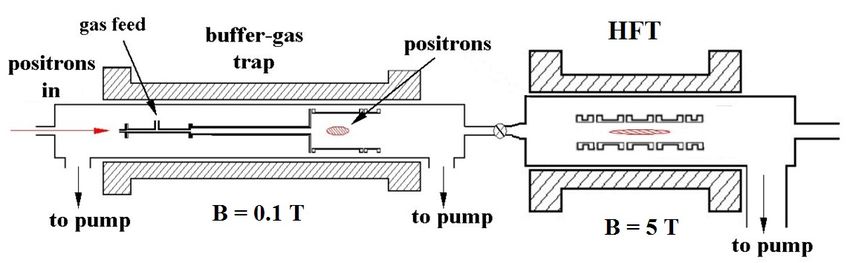
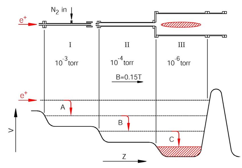
GEC October 9, 2020
 Buffer-Gas Positron Trap
 (down-home gaseous positronics!)

 1.7 m

 CF4
 ¨ Trap using electronic
 excitation of N2
 ¨ Positrons cool to 300K
 on CF4 in ~ 0.1s

 30% trapping
 efficiency
 using Ne moderator

 Surko PRL ‘88; Murphy, PR ‘92
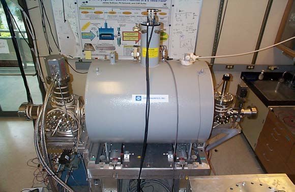
GEC October 9, 2020

 Shuttle to UHV for Long Term Storage
 UHV
 high-field trap

 Plasma cools by
 annihilation cyclotron radiation
 negligible Γ = 0.26 B ! "#
 c ≈ 0.2 s

 Confinement times
 of days possible
Surko, Greaves, Charlton
 Hyperfine Int. 1997
 50cm
GEC October 9, 2020
 Antiparticle Cooling
 Critical for Most Applications
 Collisional cooling on molecules 50 K

 Cyclotron radiation for positrons and electrons 10 K

 Laser cooling (sympathetic on Be+, for positrons) 5 K

 Evaporation (positrons or antiprotons) 10 K
 ____________________________________________
 Latest result:
 Cyclotron cooling in a resonant cavity increases
 cooling rate by x 100!* T = 10 K (B = 0.15 tesla)
 *Hunter & Fajans
 estimates of temperatures achieved to date Phys. Pl. (2018)
GEC October 9, 2020

 Increase Density by Radial Compression
 with Rotating Electric Fields
 “The Rotating Wall Technique”

 Vconf Vconf
 B
 . E
 segmented electrode

 V = VRW cos[(2pfRW) t + f] Apply a torque using a rotating
 electric field =>
(Huang, Anderegg, Hollmann, radial compression for f RW > f E
 Greaves, Danielson, 1997 - 2007)
GEC October 9, 2020

 Positron Plasma Parameters
 Trivelpiece-Gould modes*
 Magnetic field 10-2 – 5 tesla
 Number 104 - 109 mz
 mz
 mz
 Density 105 - 1010 cm-3
 Space charge 10-3 – 103 eV
 Temperature 10-3 – 1 eV
 Plasma length 1 – 30 cm
 frequency
 Plasma radius 0.5 – 10 mm Dubin PF ’93, Tinkle PP‘94
 Debye length 10-2 – 1 cm
 Confinement time 102 – 106 s
 Diagnostics:
 modes to measure N, n, T, & aspect ratio
 evaporate to measure temperature
 2D CCD images
 Surko AIP ‘99, Weber PP ‘08
GEC October 9, 2020

 Delivery
Trap-based Positron and Ps Beams
Cold Positron Beam
 Cryogenic Buffer-Gas Trap at 50 K
 Trap, cool and release:

 6.9 meV, FWHM

 CO cooling gas
 Tunable from ~ 20 meV to tens of volts

Natisin, et al., APL (2016) GEC October 9, 2020
Trap-based Beams – Bunch in Time

 “harmonic bunching” using a parabolic potential

 positrons

 Cassidy, RSI 2006
GEC October 9, 2020
Trap-based Beams – Bunch in Time
 “harmonic bunching” using a parabolic potential

 positrons

 PMT output (mV)
 00

 PMT output (mV)
 0

 -40 -2
 Buncher on
 0 Buncher off -4
 -80
 - 120 -6
 -120
 -8
 -20 -10 0 10 20 30 40 50
 time (ns)
 time focus
 15 ns pulse -> 1 ns pulse

 Cassidy, RSI 2006
GEC October 9, 2020
Manipulating Ps Atoms and Novel Ps Beams
 exploiting pulsed lasers

 Trap efficiently

 Cool

 Compress radially

 Bunch in time

 => then laser excitation

GEC October 9, 2020
GEC October 9, 2020

 High-Rydberg-state Positronium
 Tailored positron pulses, cooled, compressed in space and time

 Positron
 pulse in

 S = 1 positronium atoms
 Large principle quantum number n
 => weak positron-electron overlap, so long lifetime
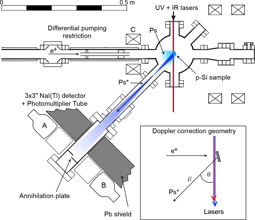
Short e+ Pulses Enable Laser Manipulation
 High-Rydberg Ps Beams
 Positron pulses, cooled, compressed in space and time. Match to lasers
 Stark states
 Create Ps in an electric field => E-field manipulation 3

control both the positron beam implantation energy and
L.
theJONES et field
 electric al. in the excitation region independently. PHYSICAL REVIEW A 90, 012503 (2014)
The former controls the kineticUV energy
 & IRof the emitted low
 Ps substates, whichfield
Ps [47]. The latter allows the Stark state degeneracy in
zero electric field to be lifted andlasers
 thus specific parts of will remain in the original Stark manifold
 seekers
the Stark manifold to be addressed by tuning the laser for 10 ! n ! 30. For Ps with n " 30, some n,m,l mixing
wavelength [24]. Specifically, in this way we may predom- will occur for the fastest atoms in the highest magnetic field

 EStark /h (THz)
inantly photoexcite Stark states with either positive or regions [19]. We note that use of an electrostatic positron beam
 Positrons
negative energy shifts, despite
 e + the limited laser resolution and magnetic shielding would eliminate the motional Stark
and Doppler broadening e↵ects.
 in
 To allow the incident positron beam to reach the target effects. Detection of annihilation γ ’s is achieved via two 3 × 3-
all electrode voltages (exceptPs*
 those applied to T and E1) in. cylindrical NaI(Tl) detectors, coupled to photomultiplier
were initially set to zero, and were then switched on af- tubes (PMTs). Detector A (see Fig. 1 for labeling) is attached
ter the beam had passed through using fast high-voltage to a Hamamatsu R2238 PMT, while B is coupled to an EMI
switches (with 10-90% voltage rise times of ⇡ 25 ns). The 9821A. The high detectors are situated outside of the vacuum
mean Ps flight time to the first electrode was ⇡ 60 ns, field
and the mean time to reach the end of the guide was chamber on opposing sides of the annihilation plate, with
 seekers
on the order of 2 µs. The -ray signals observed by de- each covering a solid angle dω/2π ≈ 15%. This arrangement
tectors D2-5 were generated primarily by Ps atoms that allows for coincident detection of the two 511-keV γ ’s
were either field ionized, or that collided with the vacuum emitted following Ps collisions with the plate. The detection
chamber walls after leaving the guide; the latter process
 of coincident pulses, as well as alternating measurements
is indicated in Fig. 1 (a) (see also Sec. IV).
 GEC October 9, 2020 performed with dipole
 giant and without the lasers, provide unambiguous
 moments
 FIG. 2. Energy level structure of the n = 13 Stark states in
 evidence
 Ps with |m| = of
 1. long-lived Ps atoms.
 The energy shift of each state, labeled with
 III. THEORETICAL BACKGROUND the index k (see text for details), is displayed over the range of
Rydberg Ps Atom Stark Focusing Mirror
Focus low-field seekers L ~ 6.0 m

 ePs ~ 0.25 eV
 reflecting
 surface - High electric field
 +
 - repels the low-field
 +
 seekers

 Jones, PRL (2017)
GEC October 9, 2020
GEC October 9, 2020

 Higher-energy Ps Beams
 Positron pulses, cooled, compressed in space and time - match to laser
 Review of
 Scientific Instruments
 ARTICLE scitation.org/journal/rsi

 Accelerate and laser-strip !
 In order to eliminate any charged particles generated in
 the Ps production chamber, such as secondary electrons from
 the converter, a pair of permanent magnets (⇠0.3 T on the sur-
 face) is mounted on the outside of the entrance of the detector

 Na-coated W film
 chamber. Therefore, the background in our detection system
 can be mainly attributed to the gamma rays of the positrons
 annihilating in the converter. Two lead shields (5 cm thick
 each) with a 10 mm center hole are also housed in the vac-
 uum chambers to further reduce the annihilation gamma-ray

 " → !
 background.

 ! + ℎ → Ps
 III. PERFORMANCE OF THE Ps BEAM SYSTEM
 We carried out production tests of the Ps beam employ-
 ing this system. Figure 6 shows the TOF spectra of the MCP
 signals, accumulated over 720 s each, with a Ps accelera-
 tion voltage of W = 5.0 kV. When the pulsed positron beam
 was incident onto the converter, a small peak was observed
 around 2 ns. The TOF of this peak corresponds to that of the
 positron annihilation gamma-rays originating from the con-
 verter. Here, the time zero of the spectra was defined as the
 beam energy 0.3 – 3 keV
 incidence time of positrons onto the converter. A delayed peak
 was clearly observed only with the laser and positron beams.
 ∘
 The TOF of this latter peak is in good agreement with that
 divergence 0.3
 calculated for Ps atoms formed p by the photodetachment of
 the accelerated Ps ions, t = L/ 2|e|W/3me + tPs = 18.0 ns,
 showing clear evidence for the Ps beam production. Here,
 tPs = 0.7 ns is the TOF of the Ps ions from the converter
 FIG. 7. Time-of-flight spectra of the MCP signals for various acceleration volt-
 to the photodetachment point as estimated by tracking sim- ages of the Ps ions, W. The kinetic energy of the Ps atoms, K Ps , formed by the
 ulations. The detection rate of the Ps atoms was 23 cps for photodetachment, was calculated as 2W/3 and is also given for each spectrum.
 W = 5.0 kV. The signal to background ratio was ⇠300, which is

 One goal: Ps diffraction from material surfaces
 high enough to perform various experiments with this beam.
 Note that the introduction of the IR laser beam into the
 chamber did not contribute to the background. Figure 7 exhibits the measured TOF spectra for various
 Ps acceleration voltages W from 0.3 kV to 5.0 kV. Here,
 was set perpendicular (90 ) to the acceleration direction of
Michishio, Nakagima, et al., RSI (2019) the Ps ions (the effect of the polarization angle is discussed
 below). The TOF of the peak of the Ps beam in each spectrum
 is shifted according to the respective acceleration voltage. The
GEC October 9, 2020

 New Science Sketches by
 A. P. Mills, Jr.

 with Antimatter
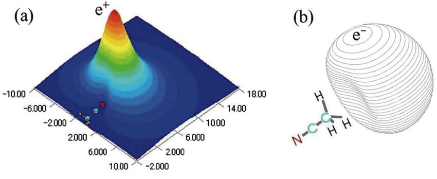
Atomic Physics
 Positrons Bind to Atoms and Molecules
 vibrational
 Feshbach resonances
 (a) e+
 (b)
 C-H
 V(r)
 wCH e
 stretch
 annihilation mode
 rate eb wCH eb
 (c)

 e = wCH - eb

 Using cold positron beam, measured binding energies for > 85 molecules

GEC October 9, 2020 Gilbert PRL, 2002; Gribakin RMP, 2010
GEC October 9, 2020

 Positron Binding to Molecules

 pp
 - -
 N N
 +C +
Acetonitrile (C2H3N) C

 p
 p
 +
 -

 predicted: eb = 135 meV Complementary theory by
 measured: eb = 180 meV Swann, Gribakin
 Dermot Green
 Tachikawa, PCCP 2011 (Belfast)

 Want to understand e+ - e- correlation & virtual positronium effects
sufficient to broaden the linewidths to the observed values.
TheAtomic
 transverse
 Physics velocity distribution of the excited state Ps

along the xPrecision
 direction was determined
 Measurement by the 100 GHz
 of the Fine Structure
excitation laser Positronium
 bandwidth,23Sbroadening
 3
 the line by less than
 1 -> 2 P0 Transition

 Positron pulses, cooled, compressed in space and time
 PHYSICAL REVIEW LETTERS 125, 073002 (2020)
 B (a) (b) define the analysis time windows used
 SiO2 h µ-wave
 antenna
 induced changes to Ps decay rates were
 VT guide the parameter Sγ ¼ ½f d ðoffÞ − f d ðonÞ'=f d ð
 D2 D1
 and (off) refer to the microwave radiation.
 Ps Spectra of the 23S1 → 23P0 transition w
 12.95 mm measuring Sγ as a function of the micro
 F UV
 laser y
 The data were corrected according to
 x dependence of the electric field intensity
 UV
 laser D3 D4
 power in a waveguide, as described by Ha
 SiO2
 x
 z
 although for the waveguide used here this
 6 mm 6.48 mm
 effect. Lorentzian functions, using ins
 weighting, were used to fit the data and obt
FIG. 1. (a) Schematic of the positronium formation and frequencies. Although more complicated li
excitation region and WR-51 waveguide and (b) the positions used [35], for symmetric
 Gurung, PRL (2020) line shapes an
 GEC October 9, 2020
of the four LYSO detectors D1-4. The spatial profile of the UV metric function (including Lorentzian profi
excitation laser light is indicated by the (blue) rectangle in (a). F same center frequencies [36].
blevel sufficient to broaden the linewidths to the observed values.
 s not The transverse velocity distribution of the excited state Ps
 etime along 9,
 GEC October the2020
 x direction was determined by the 100 GHz
 excitation laser bandwidth, broadening the line by less than
 23P0
with a Positronium 23S1 -> 23P0 Transition
-anni-
 ; self-
 atural
 τrad ≈ 4.5 s disagreement
 may
 indi-
 with theory at the
ng the ma6 level.
 mean
which ma7 in progress
 lation

e-shot
 PHYSICAL REVIEW LETTERS 125, 073002 (2020)
 lation
ortho-
placed A discrepancy!
 tic errors as described
 FIG. in the text.
 2. Example line shape and Lorentzian fit for the ν0
 transition measured in a magnetic field of 32 G using detector
 1(b). theory? (kHz) line at Δν ¼ 0 corresponds to the calculated
 Shiftvertical
 D2. The
 antity transition frequency, including the Zeeman shift. The inset shows
detec- experiment?
 $ 215
 the microwave (solid arrow) and optical (dashed arrows) tran-
00Þ ns new sitions physics?
 by which 23S1 atoms reach the 13S1 ground state.
s (< 1 V=cm)
Atomic Physics continued

 Stable, Neutral Antimatter
 Antihydrogen
 Test CPT Theorem and Gravity
 ! 1S – 2S inteval
 Compare H and H

GEC October 9, 2020
GEC October 9, 2020

 Antihydrogen Production
 Nested Penning traps
 -125
 ,̅ e+ plasmas
 antiprotons

 -100
 trapped, cooled,
 -75
 RW-compressed
 B
 -50
 0 2 4 6 8 10 12
 Length (cm)

 Trap positrons
 Launch antiprotons into mixing region
 Mix – make lots of antihydrogen!
 + + +
 Formed by three-body collisions: p + e + e = H + e
 ATHENA/ALPHA (2002-2007) ATRAP similar
! Production (gaseous leptonics)
New Protocol for H
• Use Rotating Wall
 to set n
• Use evaporative cooling to
 set the plasma potential
• -> sets N, n and rp

 Use for
 e- and e+ plasma
 reproducibility

Number of trappable
 ! increased tenfold!
 H

Ahmadi, PRL (2018)
 GEC October 9, 2020
GEC October 9, 2020

 2-Photon Spectroscopy 1S – 2S Transition in H!
 LETTER RESEARCH
 measured using SDREVC
 a 1.2
 Trappable states Disappearance, rs(D)
 Non-trappable states Appearance, rl(D)
 Simulation, 1 W
 |2Sd > 1.0

 |2Sc > 0.8
 fd–d

 > Relative
 (Laser)

 Normalized signal
 |2Sb
 0.6

 |2Sa > precision
 0.4
 2 x 10-12!
 0.2

 |1Sd > 0

 >
 |1Sc
 –0.2
 f c–b
 b 1.2
 |1S >
 (Microwave)
 110 1.15 W
 b
 FWHM (kHz at 243 nm)

 1W
 100 0.9 W
 |1S >
 Refineda spectroscopy, 1.0 90
 80 Near term goal ~ 3 x 10-15
 & gravity tests in progress 0.8 70
 l normalized to 1 W

 0.2 0.4 0.6 0.8 1.0 1.2 60
 by several groups
 Magnetic field (T)
 0.6
 50
 0.7 1.0 Ahmadi, Nature (2018)
 1.3
 ydrogenic energy levels. Calculated energies (E; for hydrogen) Laser power (W)
perfine sublevels of the 1 S (bottom) and 2 S (top) states are
 ainst magnetic field strength. The centroid energy difference 0.4
 15
GEC October 9, 2020

 Many-Electron
 Many-Positron System
 Sketches by
 A. P. Mills, Jr.
GEC October 9, 2020

 Many Body Physics with Antimatter
 electron-positron phase diagram

 n e+ - e- liquid
 normal /supercond…
 nMott~ 3 x 1022 cm-3
 density T ~ 7 x 10⁴ K

 PsBEC
 Ps BEC
 Ps BEC
 e+ - e-
 Ps
 gas plasma
 Ps2 gas

 temperature 8 x 10³ K

 (BEC º Bose-Einstein condensate)
 Yabu, NIMB ‘04
GEC October 9, 2020

 hn
 Spectroscopy of Ps2 Ps2

 Al(1,1,1)

 Doppler shifts
 Optical spectrum
 of the Ps2 molecule Ps2: 1s – 2p
 (e+e-e+e–)

 First many-electron
 many-positron state

 Cassidy, PRL 2012
remoderated Route to a Ps BEC
 beam
 108 e+ from accumulator
 5 keV -> Ni remoderator
 5 keV -> porous silica
 Ps Ps

 Ps 1.5 µ
 1.5 µm 5 x 10⁵ hat brim
 Ps
 1 x 10⁵ top of the hat
 Ps Ps Ps Ps
 e+
 goal
 n ~ 1019 cm-3
 Tc = 70 K
 4µ
 many challenges
 e.g., sample heating

Mills, Proc. ICPA (AIP 2019) GEC October 9, 2020
GEC October 9, 2020

 Classical
 Electron-Positron (“Pair”) Plasmas
 Novel nonlinear phenomena for T+= T- and n+ = n-
 • Remarkably good confinement
 • Heavily damped acoustic mode
 • Faraday rotation absent
 • Very strong nonlinear growth and damping processes*
 * Tsytovich & Wharton, Comm. on Pl. Phys. (1978)
 Relativistic e- - e+ plasmas
 • Astrophysical relevance

 Electron beam – positron plasma experiment
 Greaves, PRL (1995); Gilbert, PP (2001)
GEC October 9, 2020

 e- - e+ (“Pair”) Plasma– the APEX Collaboration
 Levitated Superconducting Magnetic Dipole

 8.2GHz Lifting magnet
 microwave

 100G 50G

 Positron test
 2930G 875G
 Electron gun experiments with
 5000G

 plasma 5000G 2.45GHz
 permanent magnet
 microwave
 Stenson, PRL 2018
 Horn-Stanja, PRL 2018
 Levitating
 Yoshida, PP (2013) magnet
 Coil catcher Coil lift

 0 0.5 1 1.5
 r (m)
 Reviews:
 Advantages Stoneking, JPP (in press)
 Pedersen, NJP (2012)
 300 s confinement
 Can confine e+ & e-
GEC October 9, 2020

 A Positron Trap on the NEPOMUC Beam in Munich
 (~ 5 x 10⁸ e+/s)
 Immediate goal: giant pulses for e+ - e- plasmas
 (the APEX collaboration)

 Will need a “multicell trap” for large N*
 ____________________________________________

 Goals for other NEPOMUC experiments:
 Positron-Auger spectroscopy using bunched e+
 Single-shot PALS (buncher for ≤ 300 ps timing)
 RW and centerline-extraction for positron microscope

 * Hurst, Phys. Plasmas (2019)
GEC October 9, 2020

 Antimatter in the Laboratory
 Gaseous Positronics is the Driver

 Much Progress and Many Opportunities

 ! Materials and atomic physics

 ! Tests of fundamental physics

 ! Antimatter plasmas & BEC Ps
GEC October 9, 2020

 Future of Antimatter Plasma Technology
 Tools
 Improved plasma compression
 Colder antimatter plasmas

 Antihydrogen
 Improved p, -positron mixing
 Antihydrogen beams

 Positron and Ps Physics
 Larger numbers of positrons
 Higher quality Ps beams
 Portable antimatter traps
GEC October 9, 2020

 Thanks to many for material and advice:

 David Cassidy, Mike Charlton, Joel Fajans, Gleb Gribakin, Christoph
 Hugenschmidt, Adric Jones, Allen Mills, Yasayuki Nagashima, Andrew
 Swann.

 and present and former collaborators:
 L Barnes, S. Buckman, J. Danielson, A. Deller, D. Dubin, S. Gilbert, S.
 Ghosh, R. Greaves, G. Gribakin, C. Hugenschmidt, N. Hurst, E. Jerzewski,
 M. Leventhal, J. Marler, T. Murphy, M. Natisin, T. O’Neil, A. Passner, T.
 Pedersen, E. Stenson, M. Stoneking, J. Sullivan, M. Tinkle, T. Weber, J.
 Young, the APEX Collaboration.

 Thanks too for support from AT&T Bell Labs, ONR, NSF, DOE, DTRA,
 and the UCSD Foundation.
GEC October 9, 2020

 e+

 Review Articles:
 Plasma and Trap-Based Techniques for Science with Positrons
 J. R. Danielson, et al., Rev. Mod. Phys. 87, 247 (2015).
 Experimental Progress in Positronium Laser Physics
 D. B. Cassidy, Euro. Phys. J. D. 72, 53 (2018)
 Plasma and Trap-Based Techniques for Science with Antimatter
 J. Fajans and C. M. Surko, Phys. Plasmas 27, 030601 (2020)

 positrons.ucsd.edu
You can also read