Practical Application of AEC Requirements for Automotive Components (Passives & ICs) - March 25, 2019 | Chris South
←
→
Page content transcription
If your browser does not render page correctly, please read the page content below
Practical Application of AEC Requirements for
  Automotive Components (Passives & ICs)

                              March 25, 2019 | Chris South

     9000 Virginia Manor Rd Ste 290, Beltsville MD 20705 | 301-474-0607 | www.dfrsolutions.com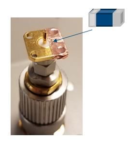
Introduction

• Automotive Electronics Council (AEC) has published a set of documents to address
  common electrical component qualification requirements
   − AEC-Q100: Failure Mechanism Based Stress Test Qualification for Integrated Circuits
   − AEC-Q101: Failure Mechanism Based Stress Test Qualification for Discrete Semiconductors
   − AEC-Q102: Failure Mechanism Based Stress Test Qualification for Discrete Optoelectronic
     Semiconductors in Automotive Applications (new 2017)
   − AEC-Q104: Failure Mechanism Based Stress Test Qualificaiton for Multichip Modules (MCM) in
     Automotive Applications (new 2017)
   − AEC-Q200: Stress Test Qualification for Passive Components

• Cover detailed qualification and re-qualification requirements
   − Includes unique test methods
   − Includes guidelines for use of generic data

                             9000 Virginia Manor Rd Ste 290, Beltsville MD 20705 | 301-474-0607 | www.dfrsolutions.com   2
                                                         Copyright of DfR Solutions 2019
AEC Document
• What does it mean?
− Components meeting these requirements are considered suitable for use in various levels of automotive
applications (interior, exterior, under hood, etc., dependent upon the grade) without additional component
level qualification testing
− Supplier can claim component is “AEC Q100 qualified”, for example, to a particular requirement within the
standard (it is NOT an all or nothing approach)
− There are no “certifications” issued, nor a certification board run by AEC to qualify parts
› Requires proper execution to the applicable AEC standards required by the customer and application
› Data available for customer review to verify compliance
› Does NOT indicate user approval
• When does it apply?
− New component qualification
− Changes to product and/or process (where it potentially impacts form, fit, function, quality, and/or reliability)
› Requalification failures require root cause analysis with corrective and preventative actions for qualification
− Customer requested
9000 Virginia Manor Rd Ste 290, Beltsville MD 20705 | 301-474-0607 | www.dfrsolutions.com 3
Copyright of DfR Solutions 2019Requirements Fit
• The Requirements Hierarchy
− Qualification to AEC document only if the
specification documents above it do not waive or PO/Purchase Agreement
detract from its requirements
Agreed Device Spec.
• Test Methods and Standards referenced
− Automotive (AEC, SAE) AEC Document
− Military
AEC Ref. Doc’s.
− Industrial (JEDEC, UL, IPC, JESD)
Supplier’s
Data
• Additional Requirements Sheet
− Supersedes requirements in the referenced test
methods/standards
9000 Virginia Manor Rd Ste 290, Beltsville MD 20705 | 301-474-0607 | www.dfrsolutions.com 4
Copyright of DfR Solutions 2019Execution
• Use generic data where possible (accelerate and streamline qualification process)
− Same major product, process, and materials elements across devices
− If similarities only, make sure worst cases of differences are covered (with technical justification)
− Use Qualification Test Plan templates (download from AEC at http://www.aecouncil.com)
• Supplier Data Sheets
− Tie the appropriate data sheet tolerances and tests to the applicable test methods outlined in AEC
− For instance, specification requirements for passives (i.e., capacitance, dissipation factor, insulation resistance, etc.) are
not dictated by AEC, but are required to perform as intended after subjected to AEC test method (i.e., THB)
− Pre-bake and post-bake: Some manufacturer’s data sheets stipulate these procedures before measurement; even though
it may not reflect real-world use (i.e., capacitors can “recover” from capacitance drift if post-baked following testing)
• Stoppages in Test/Interruptions
− Can be inevitable with lightning strikes/brown-outs in power grid (if not running a backup power generator)
− Passives undergoing THB:
› Capacitors can generally recover some once removed from THB environment after several days/weeks; limit downtime during
interim testing and disruptions, or use sealed bags to extend moisture retention by several days
› Inductors can have mixed results; while damage accumulated on inductors from THB exposure remains if pulled from test,
minimize time outside of test conditions
9000 Virginia Manor Rd Ste 290, Beltsville MD 20705 | 301-474-0607 | www.dfrsolutions.com 5
Copyright of DfR Solutions 2019Equipment/Setup
• RF Material Analyzer Equipment
− Give sufficient warm-up time after turning on equipment before using (30 minutes or more)
− Use open, short, and load standards connected to the desired reference plane (calibration reference plane)
for conducting calibration of equipment (resuming after power turned off or interrupted); use test head and
calibration kit designed for analyzer
− Error in accuracy measurement can double if calibration performed beyond controlled lab temp. (23+/-5C
for example)
− Use open/short or open/short/load compensation methods when DUT is connected to a terminal that is
extended from the calibration reference plane
− Minimize chances of electrical interference by minimizing:
› Electrical length to extension terminals
› Nearby RF devices, particularly for low impedance devices (low capacitance/inductance)
• For Passive measurements (capacitors/inductors)
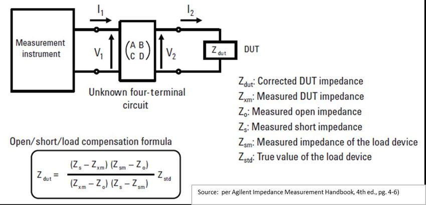
− Use break-out boards with resistors to minimize in-rush current (typicallyError Compensation
• Apply Open/Short/Load method of
compensation
− Apply when difference between measurement
of standard and measurement of known good
device differ significantly (1% to 5% can be
significant)
− Must use complex algebra (all parameters are
complex numbers with real and imaginary
components)
− Compensation method is not “bullet-proof”; to
reduce additional error being introduced
› OPEN impedance must be >100 times measured Individual component
impedance of DUT placed on port for
› SHORT impedance should beYou can also read