Proposed Extension, Refurbishment and Fit- Out Works for Network Building at EFL's Labasa Depot Tender Number: MR 36/2021
←
→
Page content transcription
If your browser does not render page correctly, please read the page content below
Proposed Extension, Refurbishment and Fit-
  Out Works for Network Building at EFL’s
              Labasa Depot

          Tender Number: MR 36/2021

                    1
Energy Fiji Limited (EFL) is a statutory body vested with the responsibility for the provision of
electricity supply throughout the Fiji Islands.

EFL is responsible for the Generation, Transmission and Retail of electricity on the larger
islands, Viti Levu, Vanua Levu and Ovalau, which account for some 90% of the country’s
population. Installed generation capacity is approximately 237MW, comprising 80MW Monasavu
Hydro Scheme and 40MW Nadarivatu Hydro Scheme in Viti Levu and about 112MW of diesel
capacity in 14 stations on the three main islands. Of the diesel capacity 92MW is on Viti Levu
which has been supplementing the Monasavu hydro scheme for the Viti Levu Interconnected
System (VLIS) which has been reaching maximum demand of 152MW. Transmission is
provided by 145km of 132kV lines (connecting Wailoa & Nadarivatu Hydro Power Stations to
the East and West coasts) and about 350km of 33kV lines. Power distribution is by means of
more than 8,000km of 11kV and 415/240V lines.

1.0 INSTRUCTION TO BIDDERS

1. Bidders are requested to read carefully the contents of the tender document.
2. Bidders are to complete the tender document and provide all the related documents
information in sufficient detail.
3. All documents must be in English language.
4. All Bidders will be informed accordingly after finalization of tender decision.
5. Bidders should note clearly the date and the time of submittal of the tender document. No late
or delayed applications will be accepted. Bidders are reminded that no supplementary material
will be entertained by EFL after the close of submission. However EFL may, if necessary, at its
sole discretion ask for any clarification regarding the submitted tender and/or related
documents.
6. All the bidders including those who have tendered are requested to get in touch with EFL’s
Supply Chain Office for any tender clarifications.

2.0 REQUIREMENTS

1. Bidder to verify all dimension on site before submitting their tender.
2. Bidder to verify all building surfaces and current condition and advise on any alteration
    before submitting their tender
3. Bidder to ensure all materials are used as per the plans and specification provided by the
    EFL.
4. Bidder to ensure all their workers have proper PPE while entering the EFL sites.
5. Bidder to ensure all cleaning and finishing works to be done within proper specification.
6. Bidder to ensure respective work are done by skilled Tradesman.
7. Bidder to use their own scaffolding, plants, machines, transportation, and services as
    necessary to complete all refurbishment work included in the specifications.
8. Bidder to coordinate with the EFL site supervisor to discuss all site issue and constraints.
9. Left over debris must be inspected by EFL and on approval from the client the same shall be
    disposed in a manner appropriate by the bidder. Debris that the client deems as not to be
    disposed shall remain the property of the client.
10. Bidder to provide full company profile.
11. Bidder to provide Tax Compliance Certificate.
12. Bidder to meet all Insurance requirements.

                                               2
13. Selected bidders are to provide methodology and work program.
14. All workmanship to be of high expected standard with very neat finish.
15. Bidder shall be liable for any damages to the property/resources and repair them at their
own cost.
16. An induction shall be done for all contractors together by respective EFL staff.
3.0 PRELIMINARIES
All Bidders are to visit site to view the works outlined in the Scope of Works. All work shall
conform to the National Building Code of Fiji for construction with reference to standard below.
Standards and Regulations including but not restricted to:
AS 1170.0 / .1 - 2002 Structural Design Actions
AS 1288-2006 Glass in Buildings. Selection & Installation
AS/NZS 1680.0:1998 Interior Lighting-Safe Movement
AS 2047-1999 Windows in Buildings. Selection & Installation
AS 2311-2000 Painting of Buildings
AS 2870-1996 Residential Slabs and Footings
AS 2904-1995 Damp proof Courses and Flashings
AS/NZS 3500-3.2:1-2003 National Plumbing and Drainage
AS 3600-2001 Concrete Structures
AS 3700-2001 Masonry Code
AS 3727-1993 Guide to Residential Pavements
AS 3740-2004 Waterproofing of Wet Areas within Residential Buildings
AS 3958.1-1991 Ceramic Tiles
34.0 OCCUPATIONAL HEALTH AND SAFETY REQUIREMENTS
During submission process:
1. Bidders shall submit a current copy of the company:
OHS Policy
Environment Policy
Personal Protective Equipment Policy
Working at heights Policy (if applicable)
Valid license of your qualified electricians and plumbers
OHS professional who will be at the site together with his photos,
qualifications and expertise
Safe Work Method Statement or Job Safety Analysis (Risk Management) of
the project that clearly define in a table format the steps of work (in chronological
order) with the associated hazards, risks and controls according to the hierarchy of
control method
Project site safety inspection checklist and a Tool Box meeting form
Workers who will be directly involved at the site with their photos, names and
designation/occupation in a A4 paper
2. Any working at heights using scaffolds more than 1.8 meter, the bidder should provide the
OHS inspection report.
3. Any Plant mentioned in the (Legal Notice 170) Health and Safety at Work Regulations 1997,
the bidder should provide the current and valid certificate.
4. Bidders shall submit sub-contractor management documents if at any stage they will involve
in the project.
During project execution:
5. The selected bidder will have to attend the Safety Induction of the project site conducted by
the respective EFL personnel.
6. The selected bidder should conduct at least a minimum of two Project meetings in a week to
discuss the project safety issues, formal site compliance, site inspections, injury report and etc.
This meeting should be recorded in the template and presented to EFL upon request.
7. Selected bidder shall provide an entry point and erect the appropriate applicable Mandatory
safety signage’s which are to be visible at all times.
9. Selected bidder shall also provide a designated OHS Notice board at the site.
10. Selected bidder should always maintain the safety barricades and signage’s during and after
the progress of the project at all times
11. The selected bidder should provide their own qualified First Aider and First Aid Kit at the site
according to the size and ratio mentioned in the (Legal Notice 25) Health and Safety at Work
(General Workplace Condition) Regulation 2003.
After the completion of project:
Should there be any hazard materials accumulated at the site, selected bidder should isolate
them properly with mesh barricades before handover to the EFL Project Manager.
4OHS Regulations 2003
The Selected Tenderers shall be responsible for ensuring all staff and the tools, equipment and
excess materials that they are required to use are all stored safely in accordance with the above
Occupational Health and Safety Regulation.
5.0 WORK PLAN
The contractor shall prepare a Work Programme, Work Safety Plan/Risk Assessment Plan in
accordance and shall submit the plan to the respective EFL personnel for his/her approval
before commencing with work on the site. This should be provided within three (3) working days
from the date of the tender award letter.
6.0 MATERIALS
The selected bidder shall ensure that the products nominated in the tender specification
shall be used unless approval for substitute products is given by EFL in writing. Substitute
product approval shall not be unreasonably withheld if quality and performance can be
assured.
The selected bidder shall ensure that the product used shall be used in strict accordance
with Manufacturer’s instructions and may be subject to the Manufacturer’s inspections as
required.
The selected bidders shall supply all the necessary materials as new and shall further
supply all necessary tools, equipment and access aids to allow the safe and prompt
execution of the contractual works.
7.0 SITE CONDITIONS
a) The selected bidder shall visit site to familiarize themselves with all aspects of the works.
b) The selected bidder shall provide adequate protection for all adjoining and adjacent building
elements. Any damage sustained as a result of the bidders work shall be repaired/ replaced to
the EFL satisfaction without cost to the EFL and shall be completed within the Contract period.
c) The selected bidder is responsible and shall allow for all types of site access, scaffolding,
ladders, hoists as well as barricades, hoardings and or temporary fences.
d) The selected bidder are responsible for and shall allow for any and all Council and regulatory
authority fees and permits where such fees & permits apply to the construction, completion and
occupation of the building.
e) The site shall be progressively kept clean with final clean up prior to hand-over.
f) The selected bidder shall identify, locate, secure and protect all existing services within the
premises.
g) The selected bidder shall prop and secure all elements that may be subject to vibration or
movement from the proposed works.
h) It is essential that the selected bidder give due consideration to the environmental conditions
within which this property exists. It will be the selected bidder responsibility to ensure, for
example, galvanizing to correct thicknesses, stainless steel components of the correct grade
and similar issues should be adhered to appropriate separation for dissimilar materials should
be allowed for to avoid any form of corrosion or cracking.
i) No Parking shall be allowed on site to the selected bidder unless approved.
j) Storage sheds if required to be supplied by the selected bidders and located as directed by
EFL.
58.0 DURATION OF WORK
The expected duration for the completion of work shall be 12 weeks.
9.0 TOBACCO /ALCOHOL/DRUG FREE ENVIROMENT
EFL maintains tobacco, alcohol, drug free environment. Any personnel of the contractor found
violating the policy will be requested to remove the product and themselves from the sites. Offensive
language or actions are not acceptable. The EFL shall have the absolute right to require
replacement of any employee the EFL deems objectionable to work on EFL premises.
10. INSURANCE REQUIREMENTS
The Contractor shall be solely responsible for all respective insurance cover of person, tools,
equipment involved in carrying out the Works.
The Contractor must obtain and maintain respective insurance cover at all relevant times
sufficient to cover any loss or costs that may be incurred and for which the Contractor is
liable in connection with the contractual works.
11. SITE VISIT
a) All interested bidders must attend a compulsory site visit and briefing as follows:
Location Date Time Contact Person
EFL Labasa Depot 24/02/21 12.00pm Shifaan – 999 2401
All bidders must come in their own proper PPE (safety boots, helmets, vests, etc) for the
site visit. No bidder will be allowed to access the roof without proper PPE’s.
b) All tenderers shall inspect and examine the site, its surroundings, and shall satisfy him/her
before submitting his/her tender, as to the nature of the work and necessity for the carrying
out the contract work.
612. SCOPE OF WORKS
Tender to Carry out Building Extension, Refurbishment and Office Fit-Out Works for Network
Building at EFL’s Labasa Depot
General Notes:
1. All building designs shall be carried out by an engineer/engineering firm recognized by the
Insurance Council of Fiji. The building shall be designed to “Structure Importance Level – 4” in
accordance to Table 3.1 of AS/NZS 1170 Part 0. A copy of signed and approved “FOR
CONSTRUCTION” drawing shall be kept at the construction site at all times, and a copy
forwarded to EFL. The Contractor shall get all statutory approvals and consents in place before
construction works starts. All reinforcement steel and structural steel shall be inspected and
approved by the EFL Project Manager before commencement of concrete pour or
commencement of next activity in case of structural steel. A copy of Documentary evidence of all
such approvals shall be kept on site, with photographs, where applicable.
2. Carry out 5.0m extension as per floor plan sketch provided. Ensure the extended portion walls
and roofing matches the present building. All roofing structures shall be structural steel including
bolts and nuts. Structural steel members shall have appropriate rust protection system zinc
galvanizing. Cyclone certified and approved roofing screws shall be used and not nails.
3. Submit proposal for roof re-alignment to cater for wall demolition and building extension.
4. There shall be proper drainage after the installation of the roof with proper guttering and
downpipes connecting to the main drain. Provide a drain management plan.
5. New extension shall have the same ceiling height as per the existing building. New ceiling board
material to be fire rated.
6. Demolish walls marked on the plan provided and ensure neat finishing. Any wall demolition that
requires the roofing to be supported needs to be planned such that the strength of the roof
support is not compromised. Install 150mm steel beam as rafter/bottom cord for strength.
13. PROJECT PRICE SUMMARY
EFL Labasa Depot
Item Trade Price - VEP
1.0 Preliminaries & General
1.1 Contractor to allow for site visit to verify all dimensions on site. Contractor shall $
include all activities and costs for transportation of personnel, equipment, and
supplies not required or included in the contract from the site. Site mobilization,
scaffolding, barricade site with mesh barricades and proper visual signs.
Ensure compliance to EFL and OHS standard
72.0 Demolition Works
2.1 Allow to demolish, remove and discard walls and other fittings as shown during $
the site visit. Any demolished material in a reusable condition may be reused
upon approval by EFL. Allow to make good damages and defects on building
after demolition works.
3.0 Extension Works
3.1 Carry out 5.0m extension as per floor plan sketch provided. Ensure the
extended portion walls and roofing matches the present building. Allow for
finishing of the extended area to match to the existing building conditions.
4.0 Construct New Training Room & Offices – First Floor
4.1 Construct new aluminum framed training room as per size provided. Construct
one x aluminum framed door and install Lockwood brand door lock and door
closer. Install 2 x aluminum framed windows with mosquito screen for the
Training Room. Run circuit and provide 15A GPO for aircon installation. Supply
and install 1 x 24,000BTU Panasonic, Toshiba, Daikin or LG brand air
conditioner unit.
4.2 Construct 2 x aluminum framed offices with doors and Lockwood brand lock
and closer. Allow to install 1 each x sliding type aluminum framed window with
mosquito screen. Run circuit and provide 2 x 15A GPO for aircon installation.
Install 2 x 12,000 BTU Panasonic, Toshiba, Daikin or LG brand air conditioner
unit.
5.0 New Toilets for First Floor
5.1 Construct 6mm cement board walls on rondo frames from both sides for male
and female toilet as per floor plan provided. Install door signages for the toilets.
5.2 Carry out tiling works for the toilets. Install 300 x 600 anti-slip tiles on the floor
and 300 x 600 gloss tiles on walls as per selection by EFL.
5.3 Allow to install 2 x Caroma brand toilet system and 1 x Caroma Urinal System
complete with all fittings and carry out all plumbing works.
5.4 Allow to install 2 x exhaust pan and windows for the toilets with mosquito
screen.
5.5 Allow for construct vanity in the toilets with mirrors. Vanity shall have single
hand basin with Doe/Pegler brand tap. Vanity top to be 20mm granite with
16mm selected melamine board cabinet.
5.6 Allow for electrical works including fixing of light and GPO for exhaust fans and
hand dryers.
6.0 Kitchen
6.1 Construct 13mm gib board walls on rondo frames from both sides for kitchen
and install door with door closure (Lockwood brand). Run circuit and provide
15A GPO for aircon installation. Supply and install 1 x 18,000BTU Panasonic,
Toshiba, Daikin or LG brand air conditioner unit.
6.2 Construct new sink bench complete with new stainless 1 & 3/4 sink, 16mm
selected melamine board cabinets, drawers and overhead, 20mm granite top
with tile backing on 6mm cement board. Supply 1 x 8 seater table with visitors
type chairs in the kitchen.
87.0 Stairway for Emergency Escape
7.1 Construct new stairway as per sketch provided. Stairway must be reinforced
and supported appropriately and filled with 18MPa concrete. Install galvanized
tubing rails for the stairway.
8.0 Door & Window Works
8.1 Remove all existing doors and windows and install new aluminum framed
windows and doors with mosquito screens. Allow for additional framing and
carpentry works to suit the aluminum type window frame installation.
8.2 Install gothic mesh on galvanized tubing cyclone shutters for all windows for the
Network Building.
9.0 Tiling Works
9.1 Tile the entire office area including the kitchen with 600 x 600 ceramic tiles with
matching grout as per EFL color selection.
10.0 New Toilet - Ground Floor
10.1 Allow to construct new toilet and shower area as shown on the sketch
provided. Construct 100mm concrete walls for 1 x female toilet, 1 x female
shower, 2 x male toilet block, 1 x male shower.
10.2 Install 3 x Caroma brand toilet system complete, 1 x Caroma brand urinal
system with all pipes, fittings and plumbing works. Install 3 x exhaust fans for
the toilets and 2 x instant Alpha brand instant hot water system in the shower
area.
10.3 Carry out tiling works for the toilets. Install 300 x 600 anti-slip tiles on the floor
and 300 x 600 gloss tiles on walls as per selection by EFL.
10.4 Run circuits and provide 15A GPO’s for hot water installation. Allow for
electrical works including fixing of light and GPO for exhaust fans and hand
dryers.
11.0 New Tool Room – Ground Floor
11.1 Construct wooden shelves in the tool room area. Allow to relocate all lockers
and place inside the tool room.
12.0 Electrical Works
12.1 Install Philips brand downlights for the entire office and kitchen area. Ensure
proper placement of downlights for sufficient illumination. Allow for new GPO’s,
light switches, circuit breakers and new sub board. All electrical works must be
carried out as per EFL regulations. Install 1 x 40 inch LED Toshiba, Samsung,
Philips, LG or Panasonic brand television set.
13.0 Painting Works
13.1 Allow for interior and exterior painting works of the building as per EFL
approved colors. Paint work is inclusive of roof, facer, eaves, all internal and
external walls, doors, window frames, stairway, ceilings, walkway, toilet blocks
and the extended building area. Refer below in the specification for paint
selection criteria for EFL.
14.0 Ceiling Works/ Repairs
914.1 Allow to repair or change ceiling boards where necessary to match to existing.
Allow for all new ceiling installation works.
15.0 Walkway construction
15.1 Construct new walkway with 75mm galvanized pipes and gable type trim deck
roof cover as per site discussion
15.2 Joinery Works
15.3 Allow to construct filing shelves using 16mm ply board and cabinets
(varnished) in the open first floor office space area as per site discussion.
16.0 Others (please specify)
16.1
Trade Totals $............................................VEP
9% VAT $............................................
Total Price $............................................ VIP-FJD
Drawings will be provided to bidders who be the attending the site visit only.
Notes:
1. All doors must be fitted with Lockwood brand door closures and locks(mortise tyoe).
2. All toilet system must be Caroma ‘Smartflush’ Caravelle 2000 Suite.
3. All taps, stop cock, pipes, shower heads must be of Pegler or Doe brand.
4. All downlights must be of Recessed Downlight Philips GBL 100 with 18W Energy Saver
Lamplight switches, GPO’s, and other electrical fittings to be of Clipsal brand or equivalent.
5. All office windows and doors will be aluminum.
6. Doors for the toilers must be made from 6mm exterior ply board on suitable framing.
7. All door locks to be of Lockwood brand.
8. All hand basin must be of Caroma brand above counter basins.
9. Claytan Urinal with bracket to suit with water supply connections to be connected straight
from the Water Mai
10. 900×600 Clear Anodised Mirrors @ 300mm above Wall Basins for Washrooms, to be Screw
Fixed to Existing Walls with Stainless Steel Screw Caps. Also supply and install chrome
mirror corners for all 4 corners.
Electrical Notes:
1. All cables to be mechanically secured & protected. Use pvc / pvc orange circular V75 0.6 /
1KV cables or TPS for internal wiring secure to steel catenary wires inside ceiling space.
2. Use circuit breakers with thermal, magnetic & fault ratings to suit supply & load conditions.
3. Contractor to liaise with EFL regarding permits & inspections.
4. Use PDL 600 series fitting for all light switches, switch toggles, normal & round - pin G.P.O
power outlets.
5. Use PDL 600 series fitting pound pin earth switched 10a G.P.O outlet for ups power outlet.
6. All circuits shall be provided with rcd protection as per EFL current standards.
107. Locate light switches relative to door swings. Check height and location on site with Designer
before installation
14. SPECIFICATION
Paint Specification:
No Paint Description Application
1 Dulux/Apco/Resene/Taubmans Weather Shield acrylic All works
undercoat
2 Dulux/Apco/Resene/Taubmans Ceiling White acrylic Ceiling
3 Dulux/Apco/Resene/Taubmans Acrylic Weather Shield Internal painting
X10 Low Sheen
4 Dulux/Apco/Resene/Taubmans Acrylic Weather Shield External painting
X10 Low Sheen
5 Dulux/Apco/Resene/Taubmans Enamel Weather Shield Framing/grills/railing
X10 Low Sheen
6 Dulux/Apco/Resene/Taubmans Weather Shield Water Exterior walls
Proof for concrete walls
Note:
All painting to be conducted as per manufactures instruction.
All colors to be confirmed by Project manager prior installation.
All surfaces are to be painted as per Project managers instructions.
Timber:
H3 treated timber for all internal and external uses.
F7 treated timber for external uses.
Lock: Lockwood door lock. (For Internal door lock) or equivalent client approved.
11CONCRETE WORK
1. PRELIMINARY
1.1 General
Refer to the General Conditions of Contract and the Preliminary and General Clauses which will also
apply to this section of the week.
1.2 Standards
The following standards shall form part of this specification
NZS 1900 9.3A : Materials and Workmanship
NZS 1900 9.3A : Metric Handbook to AZS 1900 9.3A
NZS 2086 : Ready Mixed Concrete Production
NZS 3112 : Methods of Test for concrete
NZS 3121 : Water and Aggregate for concrete
NZS 3122 : Portland Cement
1.3 Co-operation
Allow co-operate with other trades to space, position and build in all fixing bolts, pipes, sleeves,
nailing ground, chases, conduits, reinforcing, starters, weather-bars, inspection chamber, septic tank,
etc. Also co-operative with the Block layer in the filling of cavities.
2 MATERIAL
2.1 General
All material used shall be the best their respective kinds, free from all impurities, properly packaged
and supplied in top condition.
2.2 Cement
Shall be Portland cement or Rapid Hardening Portland Cement each conforming to the above
standards.
2.3 Concrete
Concrete for any major pour shall be ready mix in accordance with the above standards supplied by
a firm approved by the Architect.
2.4 Water
Water shall be clean and free from all impurities conforming to the above standards and of such
standard that if required to do so the Contractor will drink it.
3 WORKMANSHIP
All work in this section shall be carried out by tradesmen skilled in the mixing and placing of Concrete
to the satisfaction of the Architect and Engineer.
4 FORMWORK
4.1 General
Formwork may be constructed in timber and / or steel.
4.2 Timber
All timber shall be sound and free from knot holes. Timber in contact with concrete shall be not less
than 20mm thick, or resin bonded plywood constructed so as to produce mortar tight joints.
124.3 Form Oil
Where form oil is used to preserve the oil shall be of a recognized proprietary brand which shall not
affect the bond of plaster to the concrete.
4.4 Workmanship
All formwork shall be securely braced and supported to prevent any distortions due to pressure of
Concrete and loads from operations. Particular attention shall be given to all wall and beam surfaces
to render them straight and true. Formwork shall be provided with suitable clean out point to ensure
the removal of all foreign matter from the interior before each pour. Before placing concrete all forms
shall be fixed to proper lines and levels and shall be saturated with water, if form oil is not used.
4.5 Stripping
Formwork shall not be stripped before the times mentioned below. Time for normal hardening
cement.
Foundation Sides : 1 day
Beam Sides, Wall : 2 days
Columns : 5 days
Beam Soffits and slabs : 21 days
5 PLACING
The handling, placing, protection and curing of all concrete shall be strictly in accordance with NZS
1900.Chapter 9. Which forms part of this specification and shall be read in conjunction with it. Care
shall be taken to prevent segregation of the concrete spreading of the formwork and other methods
likely to cause faulty concrete work. Concrete shall not be dropped over 1350 into forms. Should
honeycombing be evident after stripping of boxing, the Engineer shall decide whether the
honeycombing has deleterious effect on the structure or appearance in which case the concrete shall
be chipped out and replace or if not of a serious nature, surface may be repaired by plastering, al at
the expense of the contractor. Adequate means of protection finished concrete surface shall be taken
and effective damp curing by use of polythene sheet or sand covering kept continuously damp is also
essential. All concrete shall be thoroughly consolidated by vibration. Minor surface blemishes on fai
face concrete.
6 PROTECTION AND CURING
Placed concrete shall be protected from rain, sun and drying winds, by suitable coverings,
immediately available on site. The whole of the surface area of concrete shall be properly cured by
being kept continuously damp for 7 days. Artifice curing such as sand kept consciously wet shall be
allowed for at all times. Polythene sheet may also be used.
7 REINFORCING
7.1 General
Refer to the Preliminary and General clauses which will also apply to this section of the work.
7.2 Standards
In addition to standards cited elsewhere the relevant provision of the following shall apply, unless
modified accordingly:-
NZS 1900 9.3A : Concrete-General requirements
NZS 3402 : Hot rolled bars for reinforcements
NZS 3421 : Hard drawn wire reinforcement
NZS 3422 : Welded reinforcing fabric
Standard arc welding (Minor Works) Witness
137.3 Read this section in conjunction with Masonry Section.
7.3 Materials
Provide all supports, hangers, spacers, and ties to approval where not shown.
7.5 Plain and deformed bars shall comply with NZS 3402P and be of mild steel and shall have a
guaranteed minimum yield point of 275 megapascals.
7.6 Welded wire fabric shall confirm with the NZS 2422.
7.7 Alternative steels for reinforcement may be approved provided that by composition, manufacture,
Certified tests of strength, elongation, fatigue resistance and walkability the alternative has equivalent
propertied to that specified above.
7.8 Origin and Specification
Before delivery provide certificate stating origin, manufacturer's mane, steel specification; also test
certificates to prove steel conforms to specifications stated. All steel delivered to site shall be clearly
marked for identifications with the relevant certificate.
7.9 Protection
Store steel clear of ground mesh under cover.
7.10 Provide walkways to approvable required.
7.11Brace adequately all reinforcement projecting more than 1200mm form concrete, cut out defects
around bars caused by movement as directed before resuming concreting.
7.12 Fabrication
Fit ties and stirrups tightly round main reinforcement.
7.13 Bend deformed bars around rollers, not fixed pins.
7.14 Bend deformed bars only once.
7.15 Tolerance and Protective Cove
Tolerance shall be as set out in Clause 12.2.1 of NZS 1900 9.3A.
7.16 The concrete cover shown in the drawings into the surface of main reinforcement.
7.17 Placing and Fastening
Support top steel on high chairs or by other approved means, precast blocks may be permitted.
7.18 Unless otherwise detailed, support slab reinforcement at maximum 1000mm, except
reinforcement 10mm in dia. and smaller at maximum 600mm centers.
7.19 Tie reinforcement with not less than 1.25 mm soft black iron wire sufficiently to maintain correct
relative positions. Bundle bars should be tied tighter at 500 ctrs with 2.65 mm min. soft wire.
7.20 Laps
Excepting as shown no lapping of reinforcement is permitted without written approval.
147.21 Where lengths of laps are not shown, as for approval.
7.22 Welding
Welding of reinforcement shall comply with "standard arc welding (minor works)' unless otherwise
specified.
7.23 Excepting as shown on welding reinforcement is not permitted without written approval.
7.24 Identify rods or bars to be welded with tags or branding.
7.25 Inspection before Concreting
Before concreting, reinforcement must be inspected by supervising officer. Arrange with Engineer
suitable time for inspection before approval. Work done without approval will be rejected.
7.26 Prior approval of cleaning, fabrication and securing reinforcement is subject to the reinforcement
being satisfactory at time of concreting.
7.27 Extra will not be paid for remedial work caused by the inspection.
8 DAMP PROOF COURSE
Where shown on drawings, lay under floor slabs on ground 0.5 polythene DPC over sand blinding.
Carefully check blinding for any protrusion likely to puncture the DPC. Tape all joints, protrusions,
around pipes, tears, etc. with pressure sensitive tape. Carry DPC under thickening in slab and seal
DPC to foundations walls. It is essential that the DPC is continuous so that dampness cannot
penetrate.
9 CONSTRUCTION AND CONTROL JOINTS
Floor slabs on ground shall be poured to a maximum of 25 M2 and length of any side is not to
exceed
7.5M. Reinforcement to be continuous and joints shall be well cleaned be in the positions indicated
on the drawings. Construction joints in beams shall be generally located at the midpoint of the span;
however the Engineer should be notified prior to pouring so that he may approve the location.
10 FOUNDATIONS
10.1 Set Out
The accurate set out of the foundations is very important to the satisfactory construction of the rest of
the building. Refer to the Drawing setting out the exact dimensions for this work.
10.2 Footings
Ensure that the bed all footings is on solid bearing, fill soft spots with weak concrete, provide a solid,
even, clean base for the pouring of the footings. Pour the footings to the shape and sizes indicated
on the structural drawings. Co-operate with the Block layer in the location all starter and construction
of the block foundation walls.
11 BEAMS
Ensure that prior to the pouring of concrete, the formwork for the bearing is adequately supported so
as to prevent deflection and spreading upon the pouring of the concrete. Pour the beam to the sizes
and profiles indicated on the structural drawings.
1512 DRAINAGE WORKS
Co-operate with the Drain layer in the construction of the septic tank, inspection chambers, etc.,
indicated on the drainage plan.
13 BLOCKWORK
Work in and co-operate with the Block layer in the construction of block walls, filing and reinforcing of
the same and location of all starters, bars etc.
14 BUILDING - IN
All to co-operate with other trades, space, and position and build in all fixing blots, pipe sleeves,
nailing, locking, chases, conduits, reinforcing, starters, weather bars, etc. as shown on the drawings.
15 TESTING
15.1 Compressing Test
Allow take three concrete test cylinders either (304.8 X 152.4) per concrete batch or as many others
as may be directed by the Engineer. These cylinders shall be taken from any random delivery of
concrete for the test or as directed by the Engineer and shall be cures on site in conditions as near as
possible to those under which the pour they were taken from being cured. The cylinders shall be
prepared from a representative sample of the delivery.
15.2 Slump Test
This test shall be made in accordance with the requirements of NZSS 3112. A Slump Test shall be
made immediately concreting is started at all times Compression Test samples are taken and at such
other times when directed. Slump tests shall be made in accordance with AZSS 3112.
15 PLASTERER
15.1 GENERAL
Refer to the Preliminary and General clauses which also apply to this section of the works.
17 EXTENT OF WORK
The work specified under this section included all applied solid plastering, cement render and hard
plaster finish to walls, internally, slab soffits, floor slabs to provide correct grades, with falls to outlets,
stairways and for applied finishes as necessary.
18 MATERIALS
18.1 Cement, Sand and Water
Cement shall be normal Portland cement as specified for Concreter. Sand shall be clean, sharp,
washed and free from salt or organic matter. All sand is passed through an approved sieve on site
prior to mixing. Water shall be of drinking quality.
18.2 Lime
Lime shall be of approved quality run to a putty before use and run through a 20 sieve.
18.3 Waterproofing Additive
Waterproofing liquid for cement shall be Colemaboid No, 1 use and run through a 20 sieve.
18.4 Storage
Store all cement lime and plaster in clean dry areas and use in order of delivery store sand in
covered bins or on clean hard surface and cover to prevent intrusion of foreign materials
1619 WORKMANSHIP
19.1 Generally
All plasterwork shall be carried out by competent tradesmen. Finish surfaces flat, even, straight, hard
and rue. Free from imperfections. Finish angles plumb and square and surfaces uniformly textured.
Carry render up walls 75mm above finished ceiling lines.
19.2 Surface Preparation
Clean surfaces of gust and loose particles. Ensure that all chasing plugging, rough cutting, pipe
sleeves or fixings on, in and through the background are completed before beginning plasterwork.
Carry out any dubbing-out-necessary. Provide key for plasterwork on dense, smooth and strong
materials by dash coating with a cement rich slurry and fine crushed stone screenings thrown on to
the surface to a depth of 3mm - 6mm without smoothing and smoothing and protect from drying out.
Before plasterwork commence, wet background surfaces to reduce suction.
19.3 Mixing
Measure materials by volume in gauge boxes and machine mix. Do not use mixes containing cement
more than two hours or mixes contain gypsum plaster more than 30 minutes after the addition of
water.
19.4 Curing
Prevent rapid drying out of plaster surfaces by spraying with water. Ensure that each coat dries out
for at least one day before applying the succeeding coat.
19.5 Protection
Protect all finished surfaces from damage by other trades and leave perfect on completion.
19.6 Control Joints
Form straight deep trowel cut finished with a "V" joint to control between background of different
materials and at construction joints.
19.7 Waterproofing Liquid
Shall be "Colemanoid No. 1" or similar and equal used in accordance with the manufacturer's
instructions.
20 LAYING
20.1 Floors
Set out floors accurately between skirting graded with falls to drainage outlets as required and bed
tiles in 3:1 cement mortar of 19mm minimum thickness. Cut tiles accurately around plumbing and
projections. Soak off and remove backing material. Grout floor joints flushed up solid with dry mix of
1:1 sand and cement mixed with waterproofing liquid and well packed.
21 CLEANING
At least 48 hours after laying is completed, scrub down tiles with soap and water.
22 LOCATIONS
Refer to floor plan for location of quarry floor tiles.
23 VINYL TILES
23.1 Materials
Vinyl flooring tiles shall be 300 X 300 X 3mm thick selected vinyl floor tiles of approved manufactures.
Contractor to allow for laying and adhesive. Adhesives for vinyl tiles shall be as recommended by the
17manufacture for particular application. Spread evenly with the correct notched tool in small areas just
ahead of the laying.
23.2 Laying
Ensure that the base surface is thoroughly clean dry before laying vinyl. Carry out tests for dampness
by approved means and confer with the manufacturer's representative as to the dryness of the base
to suit his products before laying. The builder will be held responsible for any failure of applied
flooring sue to dampness in the base. Level up concrete surfaces with a rubber based floor leveling
compound if necessary or grind to remove rough patches on high spots, remove and loose particles
and ensure surfaces are perfectly smooth and clean before laying tiles. Set tiles from centers of each
area and scribe to all walls, projections and recesses. Spread adhesive evenly over the sub-floor and
lay tiles accurately close butted. Roll tiles with a suitable roller within 30 minutes of laying. Spread
adhesive evenly over wall face and fix skirting accurately.
23.3 Finishing
Seal and polish vinyl floors on completion in accordance with the floor manufacturer’s instructions,
finishing to a uniform low sheen non-lip surface, after removing surplus adhesive and thoroughly
cleaning.
23.4 Location
Refer to floor plan for location of vinyl tiles.
24 METAL WORKERS
25 GENERAL
Refer to the Preliminary and General clauses which also apply to this section of the works.
26 EXTENT OF WORK
The work in this section included the supply and fixing of all metal items specified or shown in the
drawings or implied.
27 SAMPLES
Submit samples of finishes to metal items for the Owner's approval before work on the items
concerned is started
28 PROTECTIONS AND CLEANING
Protect all exposed metalwork during the currency of the works and on completion clean off
protective materials, using non-abrasive cleaning methods to avoid damaging finishes. The Builder
shall ensure that finished metal surfaces installed or stored on site are protected at all times from
physical damage and from cement, chemical or other stains.
29 MATERIALS
29.1 Generally
Materials shall be as specified under the particular items. Mild steel where specified shall comply with
SAA specification No. 149 Mild Steel for General Structural Purposes. Galvanizing shall be by the hot
dip process giving a coating weight of 32 oz. of pure zinc for external applications and 24 Oz
internally.
30 COVERS
Provide and build in reinforced concrete removable covers to pits, pumps and inspection chambers.
Fit heavy duty covers to vehicular traffic areas. Finish flush with adjoining surface levels.
1830.1 Cast Iron Gratings
Provide and build in light duty cast iron removable gratings to drainage sumps.
31 BRACKETS, PLATES, BOLTS, NUTS, WASHERS, STEEL STUDS ETC.
All items included in this sub-section are to be galvanized. Non- galvanized items may only be used
with the Architect's approval, but shall otherwise be rejected.
ROOFER
32. GENERAL
Refer to the Preliminary and General Clauses which apply to this section of the works.
33. EXTENT OF WORK
The work covered in this section includes the supply and fixing to all roof areas of roof coverings, roof
plumbing, and insulation and metal claddings as shown on the drawings.
34. Storage of material
Store sheet materials horizontally in a dry area and provide protective covering. Handle carefully to
avoid damage to protective coatings.
35. CLEANING
Clean away trimmings, offcuts and other surplus materials from roof areas as they accumulate, clean
out gutters and leave clean on completion.
36. ROOFING MATERIALS
36.1 Metal Roof
Supply and screw fix metal roof complete with all fixing. Fix for hurricane conditions in accordance
with manufacturer’s instructions. Supply and fix all necessary galvanized flashings to required and/ or
detailed profiles.
36.2 Insulation
Insulate under all roofs with double sided aluminum foil sisalation. Fit tightly around protrusions and
pipes.
36.3 Flashings
Flash all vent pipes and penetrations through roofing materials and leave watertight on
completion. Over flash with preflashings. Vertical flashings and capping’s shall over flash
sections below not less than 50mm. Flashings shall be galvanised.
37. ROOF PLUMBING
37.1 Eaves Gutters
Eaves gutters shall be standard UPVC Marley gutters or as selected. Fix with proprietary
brackets as per manufacturer's specification.
37.2 Down Pipes
Down pipes shall be of Class B UPVC 100 dia, complete with all junction bends and fitting
required. Adequately support on approved clips. Supply and install grate at rainwater head and
sump as detailed.
19DRAINLAYER
38. GENERAL
Refer to the Preliminary and General Clauses which apply to this section of the works.
39. EXTENT OF WORK
This work shall include the laying of all storm water, soil and sullage lines, manholes, inspection
chambers and septic tank.
40. AUTHORITIES
All work under this trade shall be installed in accordance with the By-laws and Regulations of
the Local Authorities. All work shall be carried out under the direction of a licensed drain layer.
Obtain all permits and approvals as required.
41. SOIL DRAINS
41.1 Inspection Chambers
Chambers shall be 600mm x depth as required, construction to be of 100mm thick concrete
walls and floor reinforced with 225mm mesh or 10mm dia. rods. Provide and fit concrete lids.
The drain pipe shall be cut away where it passes through the chamber. The chamber bottom
shall be steel floated to fall at a 1:2 gradient towards the pipe, incoming pipes shall discharge
above the chamber bottom.
41.2 Septic Tank
10-12 person septic tanks are required.
41.3 Sullage Drains
Lay PVC Class B sullage drains to sizes and locations shown. Lay with minimum cover and falls
as for sewer drains. Provide all bends, branches and other fittings necessary for the works.
Connect into soak holes as shown.
41.4 Inspection and Testing
All systems shall be tested in the presence of the Architect and the Health Inspector before
filling of trenches.
42. STORMWATER
Excavate for and lay agricultural lines in positions shown in drawings. Connect to open natural
drainage system. Reform to even falls with minimum grade 1:100. Carry to storm water mains
outlet. Re-form existing natural drains to even grade 1:100 minimum. Shape sides of drains to
allow for planting grass. Allow for precast concrete pipes of suitable diameter under all
buildings, walkways and traffic areas as required or necessary to connect into open drains.
20TENDER SUBMISSION CHECK LIST
The Bidders must ensure that the details and documentation mention below must
be submitted as part of their tender Bid
Tender Number _________________
Tender Name _________________________________________________________________
1. Full Company / Business Name:
(Attach copy of Registration Certificate)
2. Director/Owner(s):___________________________________________________________
3. Postal Address:_____________________________________________________________
4. Phone Contact:_____________________________________________________________
5. Fax Number:_______________________________________________________________
6. Email address:_____________________________________________________________
7. Office Location:_____________________________________________________________
8. TIN Number:
(Attach copy of the VAT/TIN Registration Certificate - Local Bidders Only (Mandatory)
9. FNPF Employer Registration Number: _________(For Local Bidders only) ( Mandatory)
10. Provide a copy of Valid FNPF Compliance Certificate ( Mandatory- Local Bidders only)
11. Provide a copy of Valid FRCS (Tax) Compliance Certificate ( Mandatory Local Bidders only)
12. Contact Person:
I declare that all the above information is correct.
Name:_________________
Position: _______________
Sign: __________________
Date:__________________
21Submission of Tender
Two (2) hard copies of the tender bids in sealed envelope shall be deposited in the
tender box located at the Supply Chain Office at the EFL Head Office, 2 Marlow
Street, Suva, Fiji.
Courier charges for delivery of Tender Document must be paid by the bidders.
This tender closes at 4:00 p.m. (16.00hrs Fiji time) on Wednesday 10th March,
2021.
Each tender shall be sealed in an envelope with the envelope bearing only the
following marking:
MR 36/2021
Carry out Extension, Refurbishment and Fit-Out Works for Network Building at EFL’s
Labasa Depot
The Secretary, Tender Committee
Energy Fiji Limited
Supply Chain Office
Private Mail Bag,
Suva
It must also indicate the name and address of the tenderer on the reverse of the
envelope.
All late tenders, unmarked Envelopes and envelopes without bidder’s name and
address on the reverse on the envelope will be returned to the Tenderers
unopened. (Bids via e-mail or fax will not be considered).
The bidders must ensure that their bid is inclusive of all Taxes payable under Fiji
Income Tax Act and must have the most current Tax Compliance Certificate.
For further information or clarification please contact our Supply Chain Office on
phone (+679) 3224360 or (+679) 9992400.
Bidders are requested to submit a:
22 Valid Tax Compliance Certificate
FNPF Compliance Certificate
FNU Certificate Certificate
The Tender Bids particularly the “Price” must be typed and not hand written.
(Tender Submission via email or fax will not be accepted)
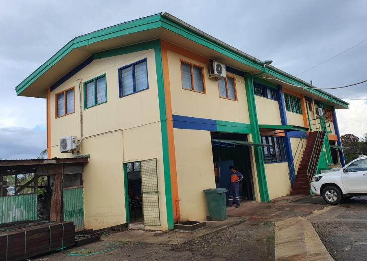
23Picture
5m extension
24You can also read