Protector XL Laboratory Fume Hoods - Models
←
→
Page content transcription
If your browser does not render page correctly, please read the page content below
Original instructions
Protector XL™
Laboratory Fume Hoods
Models
1110 Series
1111 Series
1112 Series
1113 Series
1114 Series
1115 Series
1116 Series
1117 Series
1118 Series
Original instructions

Copyright © 2019 Labconco Corporation. The information contained in this manual and the accompanying
products are copyrighted and all rights reserved by Labconco Corporation. Labconco Corporation reserves
the right to make periodic design changes without obligation to notify any person or entity of such change.

  Warranty
  Labconco Corporation provides a warranty to the original buyer for the repair or replacement of parts and
  reasonable labor as a result of normal and proper use of the equipment with compatible chemicals. Broken
  glassware and maintenance items, such as filters, gaskets, light bulbs, finishes and lubrication are not
  warranted. Excluded from warranty are products with improper installation, erratic electrical or utility supply,
  unauthorized repair and products used with incompatible chemicals.
  The warranty for Protector® XL™ Laboratory Fume Hoods will expire one year from date of installation or
  two years from date of shipment from Labconco, whichever is sooner. Warranty is non-transferable and only
  applies to the owner (organization) of record.
  Buyer is exclusively responsible for the set-up, installation, verification, decontamination or calibration of
  equipment. This limited warranty covers parts and labor, but not transportation and insurance charges. If the
  failure is determined to be covered under this warranty, the dealer or Labconco Corporation will authorize
  repair or replacement of all defective parts to restore the unit to operation. Repairs may be completed by 3 rd
  party service agents approved by Labconco Corporation. Labconco Corporation reserves the rights to limit this
  warranty based on a service agent’s travel, working hours, the site’s entry restrictions and unobstructed access
  to serviceable components of the product.
  Under no circumstances shall Labconco Corporation be liable for indirect, consequential, or special damages
  of any kind. This warranty is exclusive and in lieu of all other warranties whether oral, or implied.

Returned or Damaged Goods
Do not return goods without the prior authorization from Labconco. Unauthorized returns will not be
accepted. If your shipment was damaged in transit, you must file a claim directly with the freight carrier.
Labconco Corporation and its dealers are not responsible for shipping damages.
The United States Interstate Commerce Commission rules require that claims be filed with the delivery
carrier within fifteen (15) days of delivery.
Limitation of Liability
The disposal and/or emission of substances used in connection with this equipment may be governed by
various federal, state, or local regulations. All users of this equipment are required to become familiar with
any regulations that apply in the user’s area concerning the dumping of waste materials in or upon water,
land, or air and to comply with such regulations. Labconco Corporation is held harmless with respect to
user’s compliance with such regulations.
Contacting Labconco Corporation
If you have questions that are not addressed in this manual, or if you need technical assistance, contact
Labconco’s Customer Service Department or Labconco’s Product Service Department at 1-800-821-5525
or 1-816-333-8811, between the hours of 7:30 a.m. and 5:30 p.m., Central Standard Time.

                                          Part #9410700, Rev. I
                                               ECO L864
Original instructions

          TABLE OF CONTENTS
          CHAPTER 1: INTRODUCTION                                            1
             About This Manual                                               2
             Typographical Conventions                                       3
               (Conventions Typographiques)
             Your Next Step                                                  4

          CHAPTER 2: PREREQUISITES                                           5
             Location Requirements                                           6
             Support Requirements                                            6
             Exhaust Requirements                                            6
                   (Exigences électriques)
                Electrical Requirements                                      8
                Service Line Requirements                                    8
                Space Requirements                                           8

          CHAPTER 3: GETTING STARTED                                         9
             Unpacking Your Fume Hood                                       10
             Removing the Shipping Skid                                     10
             Sash Weight Release                                            11
             Installing the Hood on a Supporting Structure & Work Surface   11
             Connecting to the Hood Exhaust System                          13
             Connecting the Electrical Supply Source                        13
             Connecting the Service Lines to the Protector Hood             16
             Sealing the Protector Hood to the Work Surface                 17
             Certifying the Protector Fume Hood                             17

          CHAPTER 4: PERFORMANCE FEATURES AND SAFETY
                        PRECAUTIONS                                         18
             Performance Features                                           18
             Safety Precautions                                             21
                   (Consignes de sécurité)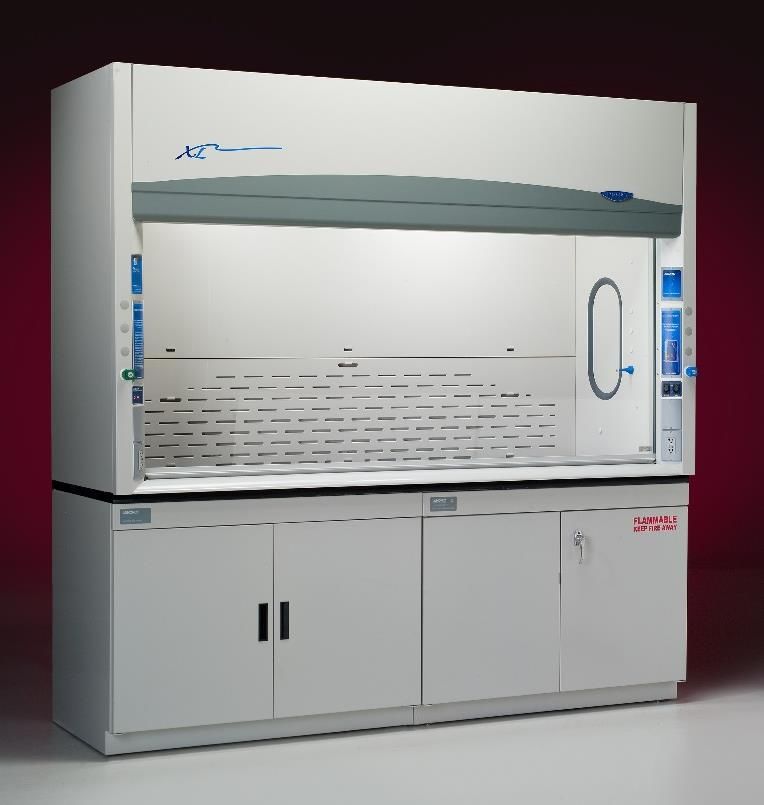
Original instructions

CHAPTER 5: USING YOUR PROTECTOR XL                                25
   Operating the Vertical Rising Sash                             25
   Operating the A-Style Combination Sash                         25
   Operating the Blower                                           25
   Operating the Lights                                           26
   Working in your Protector Fume Hood                            26

CHAPTER 6: MAINTAINING YOUR PROTECTOR XL                          28
  Service Safety Precautions                                      28
      (Mesures de sécurité des services)
   Routine Maintenance Schedule                                   29
   Routine Service Operations                                     30

CHAPTER 7: MODIFYING YOUR PROTECTOR XL                            31
   Installing Work Surfaces                                       31
   Installing Ceiling Enclosures Above the Fume Hood              32
   Installing Rear Panels Behind the Fume Hood                    34
   Installing Additional Service Fixtures                         35
   Installing Guardian Airflow Monitors                           35
   Distillation Grids – Field Installation                        35
   Sash Stop Kit – Field Installation                             36
   Upper Bypass – Field Installation                              36
   Installing an Electrical Duplex Outlet                         36
      (Installation d'une sortie Duplex électrique)

CHAPTER 8: TROUBLESHOOTING                                        37

APPENDIX A: PROTECTOR XL COMPONENTS                               40

APPENDIX B: PROTECTOR XL DIMENSIONS                               43

APPENDIX C: PROTECTOR XL SPECIFICATIONS                           44
      (ANNEXE C: SPÉCIFICATIONS PROTECTEUR DU PREMIER MINISTRE)

APPENDIX D: PROTECTOR I-S HOOD                                    47

APPENDIX E: SERIAL NUMBER TAG DESCRIPTION                         55
      (ANNEXE D: DESCRIPTION DE SÉRIE TAG NUMBER)

APPENDIX F: REFERENCES                                            61

APPENDIX G: DISASSEMBLY AND REASSEMBLY
            INSTRUCTIONS                                          64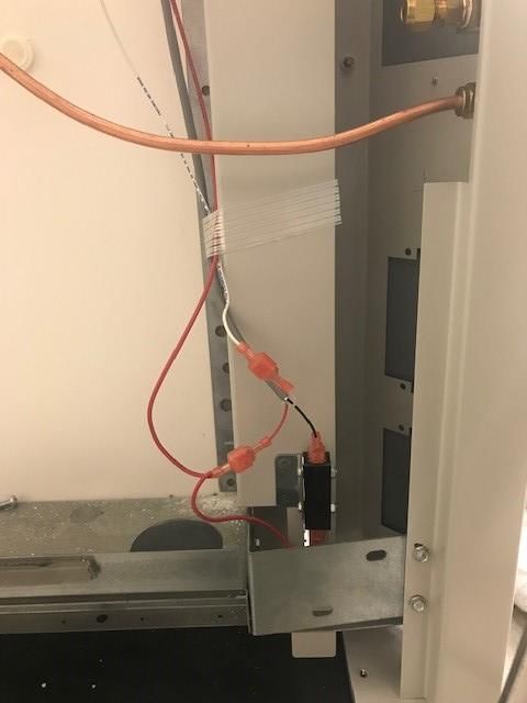
Original instructions

          CHAPTER 1
          INTRODUCTION
          Congratulations on your purchase of a Labconco Protector® XL™ Laboratory
          Fume Hood. Your Protector Laboratory Fume Hood is designed to protect you. It
          is the result of Labconco’s more than 60 years experience in manufacturing fume
          hoods, and users like you suggested many of its features to us.

          The Labconco Protector XL Fume Hood has been engineered to provide maximum
          visibility in a laboratory, and effectively contain toxic, noxious, or other harmful
          materials when properly installed. The Protector XL offers many unique features
          to enhance safety, performance, and visibility. To take full advantage of them,
          please acquaint yourself with this manual and keep it handy for future reference. If
          you are unfamiliar with how fume hoods operate, please review Chapter 4:
          Performance Features and Safety Precautions before you begin working in the
          fume hood. Even if you are an experienced fume hood user, please review
          Chapter 5: Using Your Protector XL, which describes your Protector Hood’s
          features so that you can use the hood efficiently.

                                                                                Figure 1-1

          Product Service 1-800-522-7658                                                     1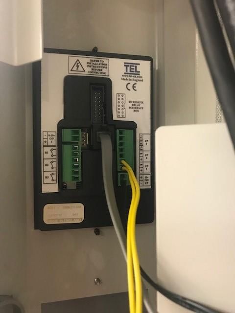
Original instructions
Chapter 1: Introduction

About This Manual
This manual is designed to help you learn how to install, use, and maintain your
laboratory fume hood. Instructions for installing optional equipment on your hood
are also included.

Chapter 1: Introduction provides a brief overview of the laboratory fume hood,
explains the organization of the manual, and defines the typographical conventions
used in the manual.

Chapter 2: Prerequisites explains what you need to do to prepare your site before
you install your laboratory fume hood. Electrical and service requirements are
discussed.

Chapter 3: Getting Started contains the information you need to properly unpack,
inspect, install, and certify your laboratory fume hood.

Chapter 4: Performance Features and Safety Precautions explains how the
Protector operates and the appropriate precautions you should take when using the
fume hood.

Chapter 5: Using Your Protector XL discusses the basic operation of your fume
hood. Information on how to prepare, use and shut down your Protector Hood are
included.

Chapter 6: Maintaining Your Protector XL explains how to perform routine
maintenance on your fume hood.

Chapter 7: Modifying Your Protector XL explains how to modify the fume hood or
add accessories.

Chapter 8: Troubleshooting contains a table of problems you may encounter while
using your laboratory fume hood including the probable causes of the problems
and suggested corrective actions.

Appendix A: Protector XL Components contains labeled diagrams of all of the
components of the fume hoods.

Appendix B: Protector XL Dimensions contains comprehensive diagrams showing
all of the dimensions for the laboratory fume hoods.

Appendix C: Protector XL Specifications contains the electrical requirements for
laboratory fume hood. Wiring diagrams are also included.

Appendix D: Serial Number Tag Description provides current rating code used on
serial number tag.

2                                               Product Service 1-800-522-7658
Original instructions
Chapter 1: Introduction
Appendix E: References lists the various resources available that deal with
laboratory fume hoods.
Appendix F: Disassembly and Reassembly Instructions lists the required tools as
well as step by step instructions for disassembling and reassembling the Protector
XL Hood.
Typographical Conventions
Recognizing the following typographical conventions will help you understand and
use this manual:
Book, chapter, and section titles are shown in italic type (e.g., Chapter 3:
Getting Started).
Steps required to perform a task are presented in a numbered format.
Comments located in the margins provide suggestions, reminders, and
references.
Critical information is presented in boldface type in paragraphs that are
! preceded by the exclamation icon. Failure to comply with the information
following an exclamation icon may result in injury to the user or permanent
damage to fume hood.
Les informations critiques sont présentées en gras dans les paragraphes qui
sont précédés par l'icône d'exclamation. Ne pas se conformer aux informations
qui suivent une icône d'exclamation peut résulter à la blessure de l'utilisateur
ou à des dommages irréversibles de la hotte aspirante.
Critical information is presented in boldface type in paragraphs that are
preceded by the wrench icon. These operations should only be performed by a
trained certifier or contractor. Failure to comply with the information
following a wrench icon may result in injury to the user or permanent damage
to your hood.
Les informations critiques sont présentées en gras dans les paragraphes qui
sont précédés par l'icône de clé plate. Ces opérations devraient être seulement
exécutées par un professionnel agrée. L'échec pour se conformer aux
informations qui suivent une icône de clé plate peut résulter à la blessure de
l'utilisateur ou à des dommages irréversibles de la hotte.
Important information is presented in capitalized type in paragraphs that are
preceded by the pointer icon. It is imperative that the information contained in
these paragraphs be thoroughly read and understood by the user.
A number icon precedes information that is specific to a particular model of
4' 5' laboratory fume hood. The 4' icon indicates the text is specific to the 4-foot
wide model. The 5' icon indicates the text is specific to the 5-foot model, etc.
6' 8'
Product Service 1-800-522-7658 3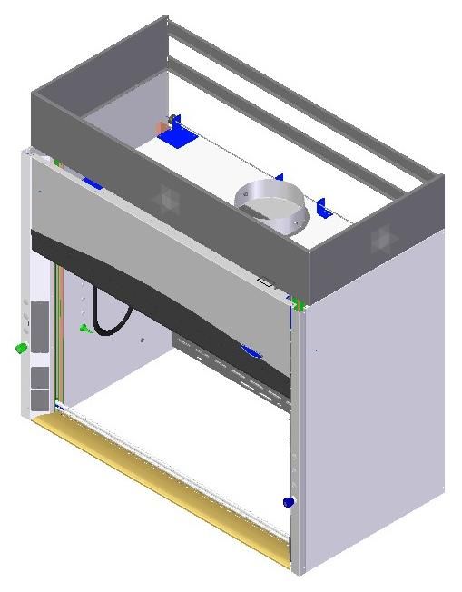
Original instructions
Chapter 1: Introduction
S The S icon indicates the text is specific to the standard model.
A The A icon indicates the text is specific to the A-Style Combination Sash
Model.
!
CAUTION – See Manual. When this symbol is on a fume hood it indicates a
caution that is detailed in this manual.
PRUDENCE – Consulter le Manuel. Quand ce symbole est sur une hotte
aspirante, il indique une prudence qui est détaillée dans ce manuel.
CAUTION – Hot Surface.
AVERTIR – Surface Chaude
CAUTION – See Manual. This symbol on the fume hood indicates the
possibility of a pinch hazard.
PRUDENCE – Consulter le Manuel. Ce symbole sur la hotte indique la
possibilité d'un risque de pincement.
Your Next Step
If your Fume Hood needs to be installed, proceed to Chapter 2: Prerequisites to
ensure your installation site meets all of the requirements. Then, go to Chapter 3:
Getting Started for instructions on how to install your laboratory fume hood and
make all of the necessary connections.
If you would like to review how laboratory fume hoods operate, go to Chapter 4:
Performance Features and Safety Precautions.
For information on the operational characteristics of your laboratory fume hood,
go to Chapter 5: Using Your Protector XL.
If your laboratory fume hood is installed and you need to perform routine
maintenance on the cabinet, proceed to Chapter 6: Maintaining Your Protector XL.
For information on making modifications to the configuration of your fume hood,
go to Chapter 7: Modifying Your Protector XL.
Refer to Chapter 8: Troubleshooting if you are experiencing problems with your
fume hood.
4 Product Service 1-800-522-7658
Original instructions
CHAPTER 2
PREREQUISITES
Before you install your laboratory fume hood, you need to prepare your site for
installation. Carefully examine the location where you intend to install your
hood. You must be certain that the area is level and of solid construction. In
addition, a dedicated source of electrical power must be located near the
installation site.
Carefully read this chapter to learn the requirements for your installation site:
The location requirements.
The support requirements.
The exhaust requirements.
The electrical power requirements.
The service line requirements.
The space requirements.
Refer to Appendix B: Protector XL Dimensions for complete fume hood
dimensions.
Refer to Appendix C: Protector XL Specifications for complete laboratory fume
hood electrical and environmental conditions, specifications and requirements.
Product Service 1-800-522-7658 5Original instructions
Chapter 2: Prerequisites
Location Requirements
The fume hood should be located away from traffic patterns,
! doors, windows, fans, ventilation registers, and any other air-
handling device that could disrupt its airflow patterns. All
windows in the room should be closed.
La hotte aspirante devrait être localisé loin des voies de
circulation, des portes, des fenêtres, des ventilateurs, des
bouches de ventilation, et de tout appareil qui pourrait
interrompre ses voies de flux d'air. Toutes les fenêtres dans la
pièce devraient être fermées.
Support Requirements
DO NOT install the fume hood on a cart, dolly, or mobile
! bench. ALL Protector Hood installations must be permanent
and stationary. The supporting structure usually consists of a
base cabinet and chemically resistant work surface.
NE PAS installer la hotte aspirante sur un chariot ou un banc
mobile. TOUTES les installations de la Hotte Protecteur
doivent être permanentes et fixes. La structure de soutien
consiste habituellement en un meuble doté d’une surface de
travail chimiquement résistante.
Exhaust Requirements
The exhaust duct connection has been designed for 12" nominal duct (12.75" OD)
to allow for minimum static pressure loss while operating at 60 to 100 fpm face
velocities. The 12" diameter exhaust duct also allows for proper transport
velocities away from the hood in the 1000 fpm to 2500 fpm range. The proper
exhaust volume and static pressure loss are listed next for each hood model:
6 Product Service 1-800-522-7658Original instructions
Chapter 2: Prerequisites
Projected Airflows and Static Pressure
Eco Energy Saving Air Foil Flush Air Foil
Hood Type Face Velocity (fpm) Airflow Volumetric Rate (CFM) @ Airflow Volumetric Rate (CFM) @
Sash at Sash at 62.5% Static Pressure (inches of water) Static Pressure (inches of water)
Full open open 4' 5' 6' 8' 4' 5' 6' 8'
at 28" at 18" Hood Hood Hood Hood Hood Hood Hood Hood
XL 100 160 725, 0.27" 955, 0.34" 1180, 0.46" 1640, 0.31" 760, 0.28" 1000, 0.36" 1235, 0.49" 1715, 0.33"
80 128 580, 0.17" 765, 0.22" 945, 0.29" 1310, 0.20" 605, 0.18" 800, 0.23" 990, 0.31" 1370, 0.21"
60 96 435, 0.10" 575, 0.12" 710, 0.17" 985, 0.11" 455, 0.10" 600, 0.13" 745, 0.18" 1030, 0.12"
50 80 365, 0.07" 480, 0.09" 590, 0.11" 820, 0.08" 380, 0.07" 500, 0.09" 620, 0.12" 860, 0.08"
40 64 290, 0.04" 380, 0.05" 470, 0.07" 655, 0.05" 305, 0.05" 400, 0.06" 495, 0.08" 685, 0.05"
Eco Energy Saving Air Foil Flush Air Foil
Hood Type Face Velocity (fpm) Airflow Volumetric Rate (CFM) @ Airflow Volumetric Rate (CFM) @
Sash at Sash at Static Pressure (inches of water) Static Pressure (inches of water)
62.50% Full open 4' 5' 6' 8' 4' 5' 6' 8'
open at 18" at 28" Hood Hood Hood Hood Hood Hood Hood Hood
XL 100 62 450, 0.11" 595, 0.13" 735, 0.18" 1025, 0.12" 485, 0.11" 640, 0.14" 790, 0.19" 1100, 0.13"
80 50 365, 0.07" 480, 0.09" 590, 0.11" 820, 0.08" 390, 0.07" 515, 0.08" 635, 0.11" 880, 0.08"
60 38 270, 0.04" 360, 0.05" 440, 0.07" 615, 0.04" 290, 0.04" 385, 0.05" 475, 0.07" 660, 0.05"
Projected Airflows and Static Pressure
Eco Energy Saving Air Foil Flush Air Foil
Hood Type Face Velocity (fpm) Airflow Volumetric Rate (CFM) @ Airflow Volumetric Rate (CFM) @
Sash at Sash at 62.5% Static Pressure (inches of water) Static Pressure (inches of water)
Full open open 4' 5' 6' 8' 4' 5' 6' 8'
at 28" at 18" Hood Hood Hood Hood Hood Hood Hood Hood
XL 100 160 705, 0.25" 930, 0.32" 1150, 0.44" 1600, 0.30" 740, 0.26" 975, 0.34" 1205, 0.47" 1675, 0.32"
W/Bypass 80 128 565, 0.16" 745, 0.21" 920, 0.28" 1280, 0.19" 590, 0.17" 780, 0.22" 965, 0.30" 1340, 0.21"
Block 60 96 425, 0.09" 560, 0.12" 690, 0.16" 960, 0.11" 445, 0.09" 585, 0.12" 725, 0.17" 1005, 0.12"
50 80 350, 0.06" 465, 0.08" 575, 0.11" 800, 0.08" 370, 0.07" 490, 0.09" 605, 0.12" 840, 0.08"
40 64 280, 0.04" 370, 0.05" 460, 0.07" 640, 0.05" 295, 0.04" 390, 0.05" 480, 0.08" 670, 0.05"
Eco Energy Saving Air Foil Flush Air Foil
Hood Type Face Velocity (fpm) Airflow Volumetric Rate (CFM) @ Airflow Volumetric Rate (CFM) @
Sash at Sash at Static Pressure (inches of water) Static Pressure (inches of water)
62.50% Full open 4' 5' 6' 8' 4' 5' 6' 8'
open at 18" at 28" Hood Hood Hood Hood Hood Hood Hood Hood
XL 100 62 440, 0.10" 580, 0.12" 720, 0.17" 1000, 0.12" 475, 0.10" 625, 0.13" 775, 0.18" 1075, 0.12"
W/Bypass 80 50 350, 0.06" 465, 0.08" 575, 0.11" 800, 0.08" 380, 0.07" 500, 0.09" 620, 0.12" 860, 0.08"
Block 60 38 265, 0.04" 350, 0.05" 430, 0.06" 600, 0.04" 285, 0.04" 375, 0.05" 465, 0.07" 645, 0.05"
Airflows and Static Pressure
Eco Energy Saving Air Foil
Hood Type Face Velocity (fpm) Airflow Volumetric Rate (CFM) @
Sash at Sash at 62.5% Static Pressure (inches of water)
Full open open 10' 12' 16'
at 28" at 18" Hood Hood Hood
XL 100 160 2100, 0.45" 2560, 0.62" 3500, 0.37"
W/Bypass 80 128 1680, 0.28" 2050, 0.39" 2800, 0.23"
Block 60 96 1260, 0.16" 1535, 0.22" 2100, 0.13"
50 80 1050, 0.11" 1280, 0.16" 1750, 0.09"
40 64 840, 0.07" 1025, 0.10" 1400, 0.06"
Eco Energy Saving Air Foil
Hood Type Face Velocity (fpm) Airflow Volumetric Rate (CFM) @
Sash at Sash at Static Pressure (inches of water)
62.50% Full open 10' 12' 16'
open at 18" at 28" Hood Hood Hood
XL 100 62 1300, 0.17" 1585, 0.24" 2170, 0.14"
W/Bypass 80 50 1050, 0.11" 1280, 0.16" 1750, 0.09"
Block 60 38 800, 0.06" 970, 0.09" 1330, 0.05"
Proper blower selection can be determined from these exhaust requirements and
the total system static pressure loss. Contact Labconco Customer Service for
assistance in sizing a blower system.
Product Service 1-800-522-7658 7Original instructions Chapter 2: Prerequisites Electrical Requirements The Protector Hood models feature internal wiring for the LED light assembly and light switch. All internal wiring is terminated at the single point wiring junction box for hook-up by a qualified electrician. The blower switch, and light switch wires are also terminated at the single point wiring junction box for hook- up by a qualified electrician. Refer to Chapter 3: Getting Started and Appendix C: Protector XL Specifications for the wiring diagram for proper electrical installation. Les modèles Protège-capot disposent câblage interne de l'assemblage de lumière LED et interrupteur de lumière. Tout le câblage interne est terminé à la boîte de jonction point de câblage unique pour le raccordement par un électricien qualifié. Le bouton du ventilateur, et fils de l'interrupteur de lumière sont également mis fin à la boîte de jonction point de câblage unique pour le raccordement par un électricien qualifié. Reportez-vous au Chapitre 3: Mise en route et à l'Annexe C: Spécifications Premier Protector pour le schéma de câblage pour l'installation électrique correcte. Service Line Requirements All service lines to the laboratory fume hood should be ¼ inch outside diameter, copper (brass for natural gas), and equipped with an easily accessible shut-off valve, should disconnection be required. Recommended operating pressure is 40 PSI, with a maximum allowable pressure of 200 PSI. Consider a pressure regulator to reduce line pressure to 40 PSI. Please check with local codes for other requirements. Space Requirements The dimensions for the different models are shown in Appendix B: Protector XL Dimensions. 8 Product Service 1-800-522-7658
Original instructions
CHAPTER 3
GETTING STARTED
Now that the site for your laboratory fume hood is properly prepared, you are
ready to unpack, inspect, install, and certify your unit. Read this chapter to learn
how to:
Unpack and move your Protector Hood.
Set up the fume hood with the supporting structure and work surface.
Connect to an exhaust system.
Connect the electrical supply source.
Connect the service lines.
Sealing the Protector Hood to the work surface.
Arrange certification of your Protector Hood.
Depending upon which model you are installing, you may need common
plumbing and electrical installation tools in addition to 5/16", 3/8", 7/16", and
1/2" wrenches, ratchets, sockets, a nut driver set, a flat-blade screwdriver, a
Phillips screwdriver, and a carpenter level to complete the instructions in the
chapter.
!
The Protector XL Hood models weigh between 400 to 1600 lbs.
(182-726 kg). The shipping skid allows for lifting with a
mechanical lift truck or floor jack. If you must lift the fume
hood manually, follow safe-lifting guidelines. Normally, the
fume hood can be slid off a hydraulic lift table and be placed
into position on top of the work surface. Do not lift by the
front air foil.
Les XL modèles de la Hotte Protecteur pèsent entre 400 à 1600
livres. (182-726 Kg). La palette bois d’envoi permet le
soulèvement par un camion muni d’un élévateur mécanique ou
par un cric rouleur. Si vous devez soulever manuellement la
hotte aspirante, respectez les règles de sécurité du soulèvement.
Normalement, la hotte aspirante peut être glissée d'une table
Product Service 1-800-522-7658 9Original instructions
Chapter 3: Getting Started
munie d’un élévateur hydraulique et être placée en position sur
la surface de travail. Ne pas soulever par l’écoulement d'air du
devant.
Unpacking Your Fume Hood
Carefully remove the shrink-wrap or carton on your fume hood and inspect it for The United
damage that may have occurred in transit. If your unit is damaged, notify the States
delivery carrier immediately and retain the entire shipment intact for inspection Interstate
Commerce
by the carrier. Commission
rules require
DO NOT RETURN GOODS WITHOUT THE PRIOR
that claims
AUTHORIZATION OF LABCONCO. UNAUTHORIZED be filed with
RETURNS WILL NOT BE ACCEPTED. the delivery
carrier
within fifteen
IF YOUR HOOD WAS DAMAGED IN TRANSIT, YOU MUST
(15) days of
FILE A CLAIM DIRECTLY WITH THE FREIGHT CARRIER. delivery.
LABCONCO CORPORATION AND ITS DEALERS ARE NOT
RESPONSIBLE FOR SHIPPING DAMAGES.
Do not discard the shipping skid or packing material for your fume hood until you
have checked all of the components and installed and tested the unit. The XL
fume hood baffles are shipped loose behind the hood and do not discard. The
upper baffle is 16.5" tall, the middle baffle is 23.3" tall, and the lower
perforated baffle is 17.3" tall. See Figure 1-1, Figure 3-1 and Figure B-1 that
shows proper XL baffle installation. Do not remove the fume hood from its
shipping skid until it is ready to be placed into its final location. Move the unit by
placing a flat, low dolly under the shipping skid, or by using a floor jack.
! Do not move the hood by tilting it onto a hand truck.
Ne pas déplacer la hotte en le penchant sur un diable.
Removing the Shipping Skid
LEAVE THE FUME HOOD ATTACHED TO ITS SHIPPING
SKID UNTIL IT IS AS CLOSE TO ITS FINAL LOCATION AS
POSSIBLE. MOVE THE HOOD BY USING A SUITABLE
FLOOR JACK, OR BY PLACING A FURNITURE DOLLY
UNDERNEATH THE SKID. DO NOT MOVE THE HOOD BY
TILTING IT ONTO A HAND TRUCK.
After you verify the fume hood components, move your hood to the location
where you want to install it. Should you require disassembly to move the hood,
then follow the instructions in Appendix F. Then, follow the steps listed next to
remove the shipping skid from your unit.
10 Product Service 1-800-522-7658Original instructions
Chapter 3: Getting Started
1. Remove the side panels by unscrewing the Phillips screws.
2. Find the hardware (bolts, washers, nuts) that attach the fume hood to
the skid and remove the hardware. Some hardware is on the sides and
some is on the back.
Sash Weight Release
To protect the fume hood from damage in shipment, the sash weight has been
secured to the back of the fume hood with screws. Simply remove the screws and
make sure the sash cables or chains are on the pulleys or sprockets before
operation of the sash. On models with more than one sash, the sash weights have
been secured to the shipping skid with lag screws. Remove the weights from the
skid and attach them to the respective sash cables using the hooks provided.
NOTE: THE SASH WEIGHT ITSELF WAS INDIVIDUALLY
MATCHED FOR THIS SPECIFIC HOOD AND SHOULD NOT
BE EXCHANGED ON ANY OTHER UNIT.
Installing the Hood on a Supporting
Structure and Work Surface
!
The Protector Hood is heavy! Use caution when lifting or
moving the unit.
La Hotte Protecteur est lourd ! Prudence en soulevant ou en
déplaçant l'objet.
When installing the Protector Fume Hood onto a chemically-resistant work surface
or benchtop, ensure that the structure can safely support the combined weight of the
fume hood and any related equipment. The work surface should be at least as wide
as the hood to properly support it. The work surface is aligned flush with the back
of the fume hood for good airflow: this will provide the correct spacing under
the air foil for proper bypass airflow. The lower base cabinets are placed flush
with the front of the work surface as shown in Figure 3-1.
!
WARNING: It is important to support the rear of the work
surface and fume hood. The cross support provides support
for the bottom of the work surface. Install the cross support
after the base cabinets and work surface are leveled and before
installing the hood.
AVERTISSEMENT : Il est important de soutenir l'arrière de
la surface de travail et la hotte aspirante. Le support
tranversal soutient le bas de la surface de travail. Installer le
support transversal après que les meubles et la surface de
travail soient nivelés et avant d'installer la hotte.
Product Service 1-800-522-7658 11Original instructions
Chapter 3: Getting Started
The following are instructions for mounting a cross support:
1. Level the base cabinets and the work surface. Work surface should be
placed flush with the back of the fume hood as shown in Figure 3-1.
2. Scribe a line on the wall or back of the base cabinet to locate the
support under the work surface.
3. Mount the support by attaching it to the wall or base cabinet.
4. Place the hood on top of the work surface and cross support.
The work surface should be smooth and durable, such as a chemically-resistant
epoxy resin. The surface should be nonporous and resistant to the acids, solvents,
and chemicals used in conjunction with the Protector Fume Hood. The work
surface should also contain a dished recessed area for containing primary spills.
Figure 3-1
Slide Upper Baffle
down for zero air
gap at this location.
1.7
Place Cross
Support Here
Dimensions Shown in Inches
Hood Internal Filler Panel
Hood Depth Depth Depth Work Surface
“B” “D” “E” Depth
31.7" 24" 8" 30"
37.7" 30" 14" 36"
43.7" 36" 20" 42"
12 Product Service 1-800-522-7658Original instructions
Chapter 3: Getting Started
Connecting to the Hood Exhaust System
WARNING: The weight of the exhaust ductwork system must
! be supported independently of the hood superstructure. Do
not allow this weight to be supported by the hood structure as
damage to the hood may occur.
AVERTISSEMENT : Le poids du système d'aspiration de
ductwork doit être soutenu d'une manière indépendante de la
superstructure de la hotte. Au cas où ce poids est supporté par
la structure de la hotte, des dommages à la hotte peuvent
arriver.
The exhaust connection should be installed by a qualified
HVAC contractor. The exhaust connection on your hood has
been designed for 12" nominal pipe (12.75" OD) to allow for
minimum static pressure loss with proper transport velocities
away from the hood. Consult Labconco Customer Service
should you require help sizing your blower for the exhaust
volume and total system static pressure loss.
La connexion d'échappement devrait être installée par un
professionnel de CVC agrée. La connexion d'aspiration sur
votre hotte a été conçue pour un tuyau nominal de 12 pouces
(12,75 pouces de diamètre externe) afin d’avoir une perte
minimale de pression statique avec les correctes flux de
transport loin de la hotte. Consulter le Service Clientèle de
Labconco si la calibration de votre soufflerie pour le volume
d'aspiration et la perte de pression statique du système le
requiert.
!
The selected exhaust duct material should match the hood
procedures and chemicals used to ensure compatibility.
Le matériel de conduit d'aspiration choisi devrait être en
conformité avec les procédures de la hotte et les produits
chimiques qui sont utilisés pour garantir la compatibilité.
Connecting the Electrical Supply Source
to the Protector Fume Hood
Prior to connecting any electrical wiring to the fume hood structure, refer to the
hood identification plate for the proper electrical requirements of your specific
model.
Product Service 1-800-522-7658 13Original instructions
Chapter 3: Getting Started
WARNING: The building electrical supply system for
!
Protector Hoods should include overload protection. A switch
or circuit breaker should be in close proximity to the
equipment and within easy reach of the operator. The switch
or circuit breaker is to be marked as the disconnecting device
for the equipment. Consult the NEC-2002 for proper
installation.
AVERTISSEMENT : Le système d’alimentation électrique de la
Hotte Protecteur doit inclure la protection contre la surcharge. Un
commutateur ou disjoncteur doit être tout près de l'équipement et
à portée facile de l'opérateur. Le commutateur ou le disjoncteur
doit être marqué comme l'appareil débranchant pour
l'équipement. Consulter le NEC-2002 pour une installation
correcte.
The identification plate, model number, serial number, and electrical connection
boxes are accessible from the front of the fume hood by removing the front panel.
The Protector XL Hood is normally wired for 115 Volt, 50/60 Hz, 20 Amp or
230Volt, 50/60 Hz, 10 Amp electrical service. Check the I.D. plate behind the
front panel for voltage verification. The number of circuits varies depending on
the model. All of the electrical connections are terminated at the field wiring
terminal box for hook-up by a qualified electrician. We recommend each circuit
be a dedicated branch circuit. However, if wired together the maximum load
allowed is the sum of individual outlets plus the rating of the unit (i.e. 2 Amps).
The single point internal junction box is used for the connection of the lights,
blower, and duplex outlets. Refer to the wiring diagram for your Protector XL in
Appendix C: Protector XL Specifications.
The fume hood is required to be grounded to the MAINS protective earthing ground
for safe operation. Using a ring terminal sized for a 10-24 machine screw, connect
the MAINS ground conductor to the grounding lug marked with the protective
earthing symbol, . Only MAINS ground conductors should be connected to the
protective earthing ground lug, no other conductors should be connected to this
grounding lug. Using wire nuts connect the MAINS supply conductors to the fume
hood supply wires. Insure that the wires are connected as per the appropriate wire
color codes for the input voltage. For 115V Phase (Hot) is black and Neutral is
white, for 230V Phase1 is brown and Phase2 is blue. Refer to the wiring diagram for
your Protector XL in Appendix C: Protector XL Specifications.
14 Product Service 1-800-522-7658Original instructions
Chapter 3: Getting Started
Internal Junction
Box
Figure 3-2
All wiring for the fume hood SHOULD be performed by a
licensed electrician and conform to all local codes. In most
cases, the hood will require the use of shielded conduit to
protect the wiring into the hood. The grounding connection
shall not be made to the terminal box cover.
Tout le câblage électrique pour la hotte aspirante devrait être
exécuté par un électricien agrée et être conforme à tous les
règles en vigueur. Dans la plupart des cas, la hotte exigera
l'usage de conduit blindé pour protéger le câblage électrique
dans la hotte. La prise de terre ne sera pas faite à la couverture
de la boîte du terminal.
Product Service 1-800-522-7658 15Original instructions
Chapter 3: Getting Started
The LED light has been mounted outside the top liner panel and is sealed from
vapors inside the hood structure. To change the fluorescent light bulbs in your
hood, you must first remove the front panel from the hood. Next remove the
knock out plugs holding the light fixture in place. Lift fixture up and replace any
deflective bulbs. Reverse order to reassemble.
Connecting the Service Lines to the
Protector Fume Hood
The hoods with service fixtures have been plumbed from the valve to the hose
connector or gooseneck for your installation convenience. Supply tubing shall be
provided by the qualified installer. Tubing can enter the hood from above,
through the back, or through the work surface to make these connections to the
service fixtures.
!
NOTE: Inspect all fittings for leakage. Tighten the fittings
slightly if needed.
NOTE : Inspecter toutes les installations à la recherche de
fuite. Resserrer les installations légèrement si nécessaires.
CAUTION: Do not use oxygen with any standard service
! fixture. Contact Labconco Customer Service for oxygen
fixture information.
PRUDENCE : Ne pas utiliser de l'oxygène avec l'accessoire de
service standard. Contacter le Service Clientèle de Labconco
pour les informations d'accessoire d'oxygène.
Should access to the hood plumbing fixture bodies be required, remove the
service access plate on the hood front corner posts by loosening their individual
screws (see item 11, Figure A-1 in Appendix A). The valve body will now be
fully exposed for any service work that may be necessary. The service fixtures
supplied on your laboratory hood are designed for use with the following services:
Air Hot Water Vacuum
Cold Water Natural Gas – See caution below
WARNING: Contact Labconco Customer Service directly
! before using any service other than those listed above in these
valves to assure full compatibility.
AVERTISSEMENT : Contacter le Service Clientèle de
Labconco directement avant d'utiliser n'importe quel service
autre que ceux énumérés au-dessus dans ces soupapes pour
assurer une pleine compatibilité.
16 Product Service 1-800-522-7658Original instructions
Chapter 3: Getting Started
CAUTION: Natural gas should be used only in the service
! fixture that has been pre-plumbed with brass tubing. Sulfur
content of the gas could cause deterioration of standard copper
supply lines.
PRUDENCE : Le gaz naturel devrait être seulement utilisé
dans l'accessoire de service qui a été pré soudé avec des tuyaux
de cuivre. Le contenu soufré du gaz pourrait causer la
détérioration des lignes d’alimentation en cuivre standard.
Sealing the Protector Hood to the Work
Surface
When the hood has been set in place, ducted, wired, and plumbed, it should be
sealed at the work surface to prevent spilled materials from collecting under the
walls of the hood. Materials such as silicone sealants are recommended to seal
the hood structure.
Certifying the Protector Fume Hood
The combination of your laboratory hood, exhaust ductwork, and exhaust blower
gives you the flexibility to change the airflow at the sash opening of your hood.
To determine the actual face velocity at the sash opening, airflow velocity
readings will need to be taken. This should be done across the sash opening of
the hood in accordance with the Industrial Ventilation Manual section on
laboratory hoods (see Appendix E: References). Labconco recommends an
average face velocity at the sash opening of 60 to 100 feet per minute. Consult
Chapter 2 for proper airflow volumes for your particular model.
Your Protector Fume Hood has been tested at the factory per ASHRAE 110-1995.
All hoods achieve an “as manufactured rating” of less than 0.05 part per million
(ppm) at 4 liters per minute (lpm); AMOriginal instructions
CHAPTER 4
PERFORMANCE FEATURES
AND SAFETY PRECAUTIONS
Performance Features:
The Protector XL Laboratory Hood is designed to meet the needs of the
laboratory scientist at OSHA approved velocities as low as 60 feet per minute.
The laboratory fume hood has been designed to effectively contain toxic, noxious,
or other harmful materials when properly installed. A fully featured by-pass hood
with baffle and air foil, this hood maintains safe airflow. Optional energy saving
A-Style Combination Sash models are also available. The hood features by-pass
airflow design that promotes full containment as the sash is moved. Airflow is
diverted behind the front panel and under the air foil to help control fluctuations
in face velocity, which occur as the sash is closed.
1. Unique sash provides maximum visibility of 37.5" high while
conserving energy by limiting sash travel to 28". Vertical-rising sash
may be raised from a closed to 28" operating height. The fume hood
features a containment-enhancing sash handle. Optional sash stops are
available to limit sash height and reduce energy usage.
2. By-pass airflow design ensures containment as the sash moves.
3. Large usable interior work depth and interior height of 48" provides
ample working space.
4. Baffle (not shown) directs airflow to the rear of the interior to provide
efficient airflow. The baffle may be removed for cleaning purposes only.
The Opti-Zone™ baffle provides optimized airflow and face velocity
profile for optimal containment.
5. Exterior access cover plates are removable for easy access to plumbing
valves and sash adjustment hardware when access through the sides is not
available.
18 Product Service 1-800-522-7658Original instructions
Chapter 4: Performance Features & Safety Precautions
6. Lift-Away™ front panel provides easy access to electrical wiring, sash
weights, and lighting fixtures.
7. Energy efficient LED lighting is located behind a laminated safety glass
shield mounted to the top of the hood. The factory-wired instant start T8
lighting is serviceable from outside the hood cavity. Additionally, the
long lasting 50,000 hour direct wired LED T8 bulbs are more energy
efficient, utilizing approximately ½ the power of fluorescent bulbs. See
Appendix A for wattage.
8. Low mounted, factory-wired light and blower switches are ADA compliant.
9. All Air Foils allow air to sweep the work surface for maximum
containment. Airfoils are offered with either Eco-Energy Saving or Flush
Foil. The Clean-Sweep™ openings create a constant barrier from
contaminants. In addition, should the operator inadvertently block the
airflow entering, the air continues to enter from under the air foil and
through the Clean-Sweep openings. See Appendix A for alternate PVC
Eco-Air Foil as PVC material resists corrosion from mineral acids.
10. Streamlined corner posts provide maximum visibility and the flexibility
to add services after installation.
11. All hoods are factory prepared for up to 8 service fixtures.
12. Duplex electrical receptacles are mounted on the right and left corner
posts as requested. Receptacles are factory-wired to hood single point
junction box.
13. Shipped fully assembled and eliminates the need for costly onsite assembly.
14. Accessory Guardian™ Digital Airflow Monitor or Guardian Airflow
Monitor continuously monitors face velocity. An audio/visual alarm
alerts the user to low airflow conditions. The right corner post is factory
prepared to accommodate the Guardian Monitor (sold separately).
15. Optional Sash Models. Sashes are offered in smooth anti-racking cable,
chain, auto-return, or Intelli-Sash.
16. Frame of epoxy-coated steel and aluminum is durable and corrosion resistant.
17. Exhaust Connection. The hood features 12" (12.75" OD pipe) exhaust
connections sized to allow for a minimum static pressure loss through the
hood structure while providing a good transport velocity through the
exhaust system.
18. Spillstopper™ Solid Epoxy Work Surface is dished to contain spills.
(Work surface is sold separately).
19. Optional Ceiling Enclosure Kits are available for a decorative facade
between the hood and the ceiling.
20. Optional Sash Stops provide a means of controlling the operating height
of the sash.
Product Service 1-800-522-7658 19Original instructions
Chapter 4: Performance Features & Safety Precautions
17
6
16
7
22
20
11
5
12
1
14
15
2
9
18
4 8
10 23
21
Figure 4-1
20 Product Service 1-800-522-7658Original instructions
Chapter 4: Performance Features & Safety Precautions
See Diagram on Page 20.
21. CAUTION – Current rating of receptacle is specified in Appendix D.
AVERTIR – Classification des prises de courant est spécifié dans l’Annexe D.
22. CAUTION – See Appendix C and D for complete current rating.
AVERTIR – Voir Annexe C et D pour la classification complete du courant.
23. CAUTION – Flammable Gas.
AVERTIR – Gaz Inflammable.
Safety Precautions
Although the laboratory hood has been engineered to maintain
! optimum operator safety, caution should always be used while
working in the hood. Prior to using the hood, check to make
sure that the exhaust blower is operating and that air is
entering the hood at its specified face velocity.
Bien que la hotte de laboratoire ait été réglée pour maintenir la
sécurité optimale de l’opérateur, la prudence devrait toujours
être utilisée en travaillant sous la hotte. Avant utiliser la hotte,
le contrôle pour s'assurer que la soufflerie d'aspiration
fonctionne et que cet air entre dans la hotte au flux spécifié.
USE GOOD HOUSEKEEPING IN THE HOOD AT ALL TIMES.
CLEAN UP SPILLS IMMEDIATELY WITH A MILD
DETERGENT. PERIODICALLY CLEAN HOOD INTERIOR,
INCLUDING FLUORESCENT LIGHT GLASS PANEL.
REPLACE BURNED OUT LIGHT BULBS TO MAINTAIN
MAXIMUM ILLUMINATION.
DO NOT OVERLOAD THE WORK SURFACE WITH
APPARATUS OR WORK MATERIAL. THE SAFE
OPERATION OF THE LABORATORY HOOD IS BASED
UPON HAVING PROPER AIRFLOW THROUGH THE
STRUCTURE. DO NOT PLACE LARGE, BULKY OBJECTS
SUCH AS BLOCK HEATERS, DIRECTLY ON THE HOOD
WORK SURFACE. INSTEAD, ELEVATE THE OBJECT 2" TO
3" ON BLOCKS TO ALLOW A FLOW OF AIR UNDER THE
OBJECT AND INTO THE LOWER REAR BAFFLE EXHAUST
SLOT. ENSURE BLOCKS ARE LEVEL AND SECURED IN
PLACE.
Product Service 1-800-522-7658 21Original instructions
Chapter 4: Performance Features & Safety Precautions
Blocking the bottom of the baffle at rear of hood will change
! the airflow pattern in the hood causing turbulence and possible
leakage at the face of the hood. (Don’t store containers or
supplies against baffles, as this will affect airflow through the
hood).
Avoid placing your head inside hood. Keep hands out of hood
as much as possible.
Bloquer le fond du déflecteur à l'arrière de la hotte changera le
modèle du flux d'air dans la hotte causant de la turbulence et
une fuite possible devant la hotte. (Ne pas emmagasiner des
récipients ou des provisions contre les déflecteurs, car ceci
affectera le flux d'air à travers la hotte).
Eviter de placer votre tête à l’intérieur de la hotte. Garder les
mains à l’extérieur de la hotte le plus possible.
Always work as far back in hood as possible. It is best to keep
all chemicals and apparatus 6" inside the front of the hood.
Toujours travailler aussi loin que possible de la hotte. Il est
recommandé de garder tous les produits chimiques et appareils
à 6 pouces à l’intérieur de l’avant de la hotte.
This hood does not feature explosion-proof electrical
components, unless ordered separately. Therefore, use of
flammable or explosive materials in quantities above the
explosive limit are not recommended.
Cette hotte ne possède pas de composants électriques anti-
explosion, à moins que commandé séparément. Donc, l'usage
de matériels inflammables ou explosifs dans les quantités au-
dessus de la limite explosive n'est pas recommandé.
Do not work with chemicals in this hood without the exhaust
system running. Do not store chemicals in a fume hood.
Ne pas travailler avec les produits chimiques sous cette hotte
sans le système de d’aspiration en marche. Ne pas stocker des
produits chimiques sous une hotte aspirante.
Perchloric acid use in this hood is prohibited.
L'usage d’acide perchlorique sous cette hotte est interdit.
22 Product Service 1-800-522-7658Original instructions
Chapter 4: Performance Features & Safety Precautions
High level radioisotope materials are prohibited for usage in
this hood.
Les matériels d'isotope radioactif de haut niveau sont interdits
à l'usage sous cette hotte.
AVOID CROSS DRAFTS AND LIMIT TRAFFIC IN FRONT OF
THE HOOD. AIR DISTURBANCES CREATED MAY DRAW
FUMES OUT OF THE HOOD.
The use of heat-generating equipment in this hood without the
! exhaust system operating properly can cause damage to the
hood.
L'usage d'équipement chaleur-produiant dans ce capuchon
sans l'opération de système d'aspiration peut causer
convenablement des dommages à la hotte.
The Protector Laboratory Hood should be certified by a
qualified certification technician before it is initially used. The
hood should be re-certified whenever it is relocated, serviced or
at least annually thereafter.
La Hotte de Laboratoire Protecteur devrait être certifié par un
technicien de certification qualifié avant qu'elle soit utilisée au
début. La hotte devrait être re-certifiée quand elle est
réinstallée, entretenue ou du moins annuellement par la suite.
Ensure that the unit is connected to electrical service in
accordance with local and national electrical codes. Failure to
do so may create a fire or electrical hazard. Do not remove or
service any electrical components without first disconnecting
the hood from electrical service.
Garantir que l'unité est connectée au service électrique
conformément aux règles électriques en vigueur. Le non-
respect peut créer un feu ou un risque d'origine électrique. Ne
pas enlever ou entretenir des composants électriques sans
débrancher premièrement l’alimentation électrique de la hotte.
Proper operation of the fume hood depends largely upon the
hood’s location and the operator’s work habits. Consult the
Reference Manual in Appendix E.
Le correct fonctionnement de la hotte d'aspiration dépend
principalement de son emplacement et les habitudes de travail
Product Service 1-800-522-7658 23Original instructions
Chapter 4: Performance Features & Safety Precautions
de l'opérateur. Consulter le Manuel de Référence dans
l'Annexe E.
If the unit is not operated as specified in this manual it may
impair the protection provided by the unit.
Si l'unité n'est pas utilisée comme spécifié dans ce manuel il
peut diminuer la protection fournie par l'unité.
! Do not touch the blower motor. The surfaces of the motor can
become hot and could cause burns.
Ne pas toucher le moteur de soufflerie. Les surfaces du moteur
peuvent devenir chaudes et pourrait causer des brûlures.
! Do not position the fume hood so that it is difficult to operate
the main disconnect device.
Ne pas positionner la hotte de sorte qu'il est difficile de faire
fonctionner le dispositif principal de déconnexion.
To prevent the possibility of minor injury keep hands and
fingers clear of sprockets at the top of the four corners.
Pour éviter les risques de blessures mineures garder les mains
et les doigts de pignons en haut de la quatre coins.
24 Product Service 1-800-522-7658Original instructions
CHAPTER 5
USING YOUR PROTECTOR XL
S Operating the Vertical-Rising Sash
Because of the Protector Hood counterbalanced sash mechanism, it will take only
a few pounds of force to move the sash up or down, and you can operate the sash
smoothly with one or two hands positioned any where along the handle. The
vertical-rising sash may be raised to a maximum 28" operating height. The
airflow requirements should be sized for the 28" operating height; if using sash
stops then the airflow requirements can be reduced by approximately 40% at 18".
See Chapter 2 for airflows. Optional models with auto-return to 18" or electric
Intelli-Sash are available.
A Operating the A-Style Combination Sash
Some other hood models have additional energy saving sashes called A-Style
Combination Sashes in place of vertical-rising sashes. These combination sashes
allow the operator to use the hood with sashes either half open horizontally or
vertically to conserve energy. The horizontal sashes are used in normal operating
mode. Optional sets of sash stops can be installed to prevent raising the vertical
sash above the half-open and fully-closed positions unless manually defeated by
the operator. The airflow requirements are sized for the 50% open sash condition.
S A Operating the Blower
Your Protector Fume Hood utilizes a remote style blower, which can be activated
by turning the blower switch to “ON.” You can validate the hood performance by
watching smoke drawn into the hood face opening.
Product Service 1-800-522-7658 25Original instructions
Chapter 5: Using Your Protector XL
S A Operating the Lights
Your Protector Fume Hood utilizes a factory-wired LED light to illuminate the
hood interior (see Appendix A). Simply turn the light switch to “ON” to operate.
Working in your Protector Fume Hood
Planning
Thoroughly understand procedures and equipment required before
beginning work.
Arrange for minimal disruptions, such as room traffic or entry into the
room while the hood is in use.
Start-up
Turn on light and hood blower.
Slowly raise the sash.
Check the baffle air slots for obstructions.
Allow the hood to operate unobstructed for 5 minutes.
Wear a long sleeved lab coat and rubber gloves. Use protective eyewear.
Wear a protective mask if appropriate.
Loading Materials and Equipment
Only load the materials required for the procedure. Do not overload the
hood.
Do not obstruct the front air foil, or rear baffle slots.
Large objects should not be placed close together and spaced above the
work surface to permit airflow to sweep under the equipment.
After loading the hood, wait one minute to purge airborne contaminants
from the work area.
Work Techniques
Keep all materials at least 6 inches inside of the sash, and perform all
contaminated operations as far to the rear of the work area as possible.
Segregate all clean and contaminated materials in the work area.
Avoid using techniques or procedures that disrupt the airflow patterns of
the hood.
Final Purging
Upon completion of work, the hood should be allowed to operate for two
to three minutes undisturbed, to purge airborne contaminants from the
work area before shutting down blower.
26 Product Service 1-800-522-7658Original instructions
Chapter 5: Using Your Protector XL
Unloading Materials and Equipment
Objects in contact with contaminated material should be surface
decontaminated before removal from the hood.
All open trays or containers should be covered before being removed from
the hood.
Shutdown
Turn off the light and hood blower, then close the sash.
Product Service 1-800-522-7658 27Original instructions
CHAPTER 6
MAINTAINING YOUR
PROTECTOR XL
Now that you have an understanding of how to work in the fume hood, we will
review the suggested maintenance schedule and the common service operations
necessary to maintain your fume hood for peak performance.
Service Safety Precautions
If performing any electrical maintenance, always disconnect the power at
the main disconnect.
If performing decontamination inside the fume hood, consult your safety
officer for proper personal protective equipment and procedure.
Since some service operations require a step ladder, always use proper
safety and consult your safety officer
If performing maintenance on any service lines, always shut off the supply
first.
Some removable components may be heavy, follow safe-lifting guidelines.
Verify all components are installed correctly with performance verified
before conducting normal operations.
Précautions de Sécurité pour l’Entretien
Lors de l'entretien électrique, toujours débrancher le courant du secteur
principal.
Durant la décontamination sous la hotte d'aspiration, consulter votre
responsable de sécurité pour le correct équipement de protection du
personnel et la procédure.
Puisque certaines opérations d’entretien exigent plusieurs étapes, toujours
utiliser la correcte sécurité et consulter votre responsable de sécurité
28 Product Service 1-800-522-7658You can also read