PULL DISC HARROW MODELS DHP8, DHP10, DHP12 - Bush Hog
←
→
Page content transcription
If your browser does not render page correctly, please read the page content below

PULL DISC
                                                                        HARROW
                                                      MODELS DHP8, DHP10, DHP12
Published 05/21                                                                              Part NO. 50072116

                         OPERATOR’S MANUAL
                  This Operator's Manual is an integral part of the safe operation of this machine and must
                  be maintained with the unit at all times. READ, UNDERSTAND, and FOLLOW the Safety
                  and Operation Instructions contained in this manual before operating the equipment. C01-
                  Cover

                   ®
BUSH HOG
2501 Griffin Ave.
Selma, AL 36703
334-874-2700
www.bushhog.com
                                                                                                         $0.00
                                           ©2021 Alamo Group Inc.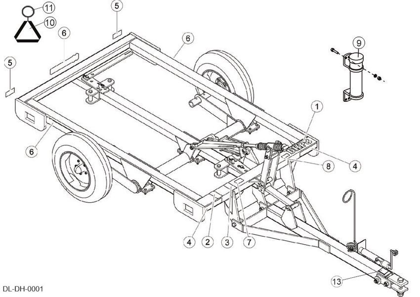
To the Owner/Operator/Dealer
All implements with moving parts are potentially hazardous. There is no substitute for a cautious, safe-minded
operator who recognizes the potential hazards and follows reasonable safety practices. The manufacturer has
designed this implement to be used with all its safety equipment properly attached to minimize the chance of
accidents.

BEFORE YOU START!! Read the safety messages on the implement and shown in your manual. Observe the
rules of safety and common sense!

WARRANTY INFORMATION:

Read and understand the complete Warranty Statement found in this Manual. Fill out the Warranty Registration
Form in full and return it to within 30 Days. Make certain the Serial Number of the Machine is recorded on the
Warranty Card and on the Warranty Form that you retain

TABLE OF CONTENTS
SAFETY SECTION ............................................................................................................... 1-1

General Safety Instructions and Practices .......................................................................................................... 1-2
Operator Safety Instructions and Practices ........................................................................................................ 1-3
Equipment Operation Safety Instructions and Practices..................................................................................... 1-5
Connecting or Disconnecting Implement Safety Instructions and Practices ....................................................... 1-7
Maintenance and Service Safety Instructions and Practices .............................................................................. 1-7
Transporting Safety Instructions and Practices .................................................................................................. 1-9
Concluding Safety Instructions and Practices...................................................................................................1-11
Decal Location .................................................................................................................................................. 1-12
Decals ............................................................................................................................................................... 1-13
FEDERAL LAWS AND REGULATIONS ........................................................................................................... 1-14

INTRODUCTION SECTION.................................................................................................. 2-1

FEATURES ......................................................................................................................................................... 2-4

ASSEMBLY SECTION ......................................................................................................... 3-1

DEALER SET-UP INSTRUCTIONS.................................................................................................................... 3-2
AXLE ASSEMBLY .............................................................................................................................................. 3-2
SPINDLE/HUB/WHEEL ASSEMBLY .................................................................................................................. 3-2
THREADED ROD ASSEMBLY ........................................................................................................................... 3-3
HITCH ASSEMBLY............................................................................................................................................. 3-3
HYDRAULIC CYLINDER ASSEMBLY................................................................................................................ 3-4
GANG ARM ASSEMBLY .................................................................................................................................... 3-5
DISC GANG ASSEMBLY ................................................................................................................................... 3-6
Disc Gang Positioning......................................................................................................................................... 3-7
OPTIONAL SCRAPER KITS ASSEMBLY .......................................................................................................... 3-7
OPTIONAL CENTER SWEEP ASSEMBLY........................................................................................................ 3-8
PARKING BRAKE............................................................................................................................................... 3-9
SLOW MOVING VEHICLE SIGN........................................................................................................................ 3-9

OPERATION SECTION ........................................................................................................ 4-1

Standard Equipment and Specifications ............................................................................................................. 4-3
OPERATOR REQUIREMENTS .......................................................................................................................... 4-4
TRACTOR REQUIREMENTS.............................................................................................................................4-5
ROPS and Seat Belt ........................................................................................................................................... 4-5
Tractor Safety Devices........................................................................................................................................ 4-5
Tractor Horsepower ............................................................................................................................................ 4-5
Front End Weight ............................................................................................................................................... 4-5
GETTING ON AND OFF THE TRACTOR .......................................................................................................... 4-6
Boarding the Tractor ........................................................................................................................................... 4-6
Dismounting the Tractor...................................................................................................................................... 4-7
STARTING THE TRACTOR ............................................................................................................................... 4-7
CONNECTING THE IMPLEMENT TO THE TRACTOR ..................................................................................... 4-8
Connecting the Disc Harrow ............................................................................................................................... 4-8
Slow Moving Vehicle Sign................................................................................................................................... 4-9
Bleeding Hydraulic Lines .................................................................................................................................... 4-9
PRE-FIELD ADJUSTMENTS............................................................................................................................ 4-10
Side to Side Leveling ........................................................................................................................................ 4-10
Front to Rear Leveling ...................................................................................................................................... 4-10
Disc Gang Adjustment ...................................................................................................................................... 4-10
IN-FIELD ADJUSTMENTS ............................................................................................................................... 4-11
Hydraulic Cylinder Depth Adjustment ...............................................................................................................4-12
Disc Gang Angle ............................................................................................................................................... 4-12
Disc Leveling Front to Rear .............................................................................................................................. 4-12
Disc Blade Replacement................................................................................................................................... 4-12
PRE-OPERATION INSPECTION AND SERVICE ............................................................................................4-12
Tractor Pre-Operation Inspection/Service......................................................................................................... 4-13
Implement Pre-Operation Inspection/Service ...................................................................................................4-13
DRIVING THE TRACTOR AND IMPLEMENT .................................................................................................. 4-17
Starting the Tractor ........................................................................................................................................... 4-18
Brake and Differential Lock Setting................................................................................................................... 4-18
Driving the Tractor and Implement....................................................................................................................4-19
OPERATING THE TRACTOR AND IMPLEMENT............................................................................................4-19
Field Operating Instructions .............................................................................................................................. 4-19
DISCONNECTING THE IMPLEMENT FROM THE TRACTOR........................................................................ 4-20
IMPLEMENT STORAGE ..................................................................................................................................4-20
TRANSPORTING THE TRACTOR AND IMPLEMENT .................................................................................... 4-21
Transporting on Public Roadways ....................................................................................................................4-21
Hauling the Tractor and Implement................................................................................................................... 4-23
TROUBLESHOOTING ...................................................................................................................................... 4-24

MAINTENANCE SECTION................................................................................................... 5-1

LUBRICATION .................................................................................................................................................... 5-2
PROPER TORQUE CHART FOR FASTENERS ................................................................................................ 5-2
SAFETY SECTION

 Safety Section 1-1
SAFETY

         General Safety Instructions and Practices
         A careful operator is the best operator. Safety is of primary importance to the manufacturer and should be to
         the owner/operator. Most accidents can be avoided by being aware of your equipment, your surroundings, and
         observing certain precautions. The first section of this manual includes a list of Safety Messages that, if
         followed, will help protect the operator and bystanders from injury or death. Read and understand these Safety
         Messages before assembling, operating or servicing this Implement. This equipment should only be operated
         by those persons who have read the manual, who are responsible and trained, and who know how to do so
         responsibly.
                     The Safety Alert Symbol combined with a Signal Word, as seen below, is used throughout this
                     manual and on decals which are attached to the equipment. The Safety Alert Symbol means:
                     “ATTENTION! BECOME ALERT! YOUR SAFETY IS INVOLVED!” The Symbol and Signal Word
SAFETY

                     are intended to warn the owner/operator of impending hazards and the degree of possible injury
                     faced when operating this equipment.

                  Practice all usual and customary safe working precautions and above all---remember safety is
                  up to YOU. Only YOU can prevent serious injury or death from unsafe practices.

                            Indicates an imminently hazardous situation that, if not avoided, WILL result in DEATH OR
                            VERY SERIOUS INJURY.
                            Indicates an imminently hazardous situation that, if not avoided, COULD result in DEATH
                            OR SERIOUS INJURY.
                            Indicates an imminently hazardous situation that, if not avoided, MAY result in MINOR
                            INJURY.
                            Identifies special instructions or procedures that, if not strictly observed, could result in
                            damage to, or destruction of the machine, attachments or the environment.

         NOTE: Identifies points of particular interest for more efficient and convenient operation or repair.(SG-1)

         READ, UNDERSTAND, and FOLLOW the following Safety Messages. Death or serious
         injury may occur unless care is taken to follow the warnings and instructions stated in the
         Safety Messages. Always use good common sense to avoid hazards. (SG-2)

                            Si no lee ingles, pida ayuda a alguien que si lo lea para que le traduzca las
                            medidas de seguridad. (SG-3)

         DHP8, DHP10, DHP12        05/21              Safety Section 1-2

         © 2021 Alamo Group Inc.
SAFETY
There are obvious and hidden potential hazards in the operation of this Implement as in all
power-driven or pulled equipment. REMEMBER! This machine is often operated in rough
terrain conditions that include grass, weeds, gullies, holes, slopes, hidden obstructions and
the like. Serious injury or even death may occur unless care is taken to assure the safety of
the operator and bystanders in the area. Do not operate this machine with anyone in the
immediate area. Stop operating if anyone comes within 25 feet of the equipment. (STL-4)
Operator Safety Instructions and Practices
Never operate the Tractor or Implement until you have read and
SAFETY
completely understand this Manual, the Tractor Operator’s Manual, and
each of the Safety Messages found in the Manual or on the Tractor and
Implement. Learn how to stop the tractor engine suddenly in an
emergency. Never allow inexperienced or untrained personnel to operate
the Tractor or Implement without supervision. Make sure the operator
has fully read and understood the manuals prior to operation. (SG-4)
The operator and all support personnel should wear hard hats, safety
shoes, safety glasses, and proper hearing protection at all times for
protection from injury including injury from items that may be thrown by
the equipment. (SG-16)
P R O L O N G E D E X P O S U R E T O L O U D N O I S E M AY C A U S E
PERMANENT HEARING LOSS! Tractors with or without an Implement
attached can often be noisy enough to cause permanent hearing loss.
We recommend that you always wear hearing protection if the noise in
the Operator’s position exceeds 80db. Noise over 85db over an
extended period of time will cause severe hearing loss. Noise over 90db
adjacent to the Operator over an extended period of time will cause
permanent or total hearing loss. NOTE: Hearing loss from loud noise
[from tractors, chain saws, radios, and other such sources close to the
ear] is cumulative over a lifetime without hope of natural recovery. (SG-I7)
Always read carefully and comply fully with the manufacturer’s
instructions when handling oil, solvents, cleansers, and any other
chemical agent. (SG-22)
KEEP AWAY FROM ROTATING ELEMENTS to prevent entanglement
and possible serious injury or death. (SG-24)
DHP8, DHP10, DHP12 05/21 Safety Section 1-3
© 2021 Alamo Group Inc.SAFETY
Never allow children to play on or around Tractor or Implement. Children can slip or fall off
the Equipment and be injured or killed. Inadvertent contact with controls can cause the
Implement to shift or fall crushing themselves or others. (SG-25)
DO NOT use drugs or alcohol immediately before or while operating the
Tractor and Implement. Drugs and alcohol will affect an operator’s
alertness and coordination and therefore affect the operator’s ability to
operate the equipment safely. Before operating the Tractor or Implement,
an operator on prescription or over-the-counter medication must consult
a medical professional regarding any side effects of the medication that
would hinder their ability to operate the Equipment safely. NEVER
knowingly allow anyone to operate this equipment when their alertness or
SAFETY
coordination is impaired. Serious injury or death to the operator or others
could result if the operator is under the influence of drugs or alcohol. (SG-27)
Prolonged operation may cause operator boredom and fatigue affecting safe operation.
Take scheduled work breaks to help prevent these potentially impaired operating
conditions. Never operate the Implement and Tractor in a fatigued or bored mental state
which impairs proper and safe operation. (SG-32)
Use extreme caution when getting onto the Implement to perform repairs, maintenance and
when removing accumulated material. Only stand on solid flat surfaces to ensure good
footing. Use a ladder or raised stand to access high spots which cannot be reached from
ground level. Slipping and falling can cause serious injury or death. (SG-33)
Avoid contact with hot surfaces including hydraulic oil tanks, pumps, motors, valves and
hose connections. Relieve hydraulic pressure before performing maintenance or repairs.
Use gloves and eye protection when servicing hot components. Contact with a hot surface
or fluid can cause serious injury from burns or scalding. (SG-34)
DO NOT operate this Implement on a Tractor that is not properly maintained. Should a
mechanical or Tractor control failure occur while operating, immediately shut down the
Tractor and perform repairs before resuming operation. Serious injury and possible death
could occur from not maintaining this Implement and Tractor in good operating condition.
(SG-36)
Avoid contact with hot surfaces of the engine or muffler. Use gloves and eye protection
when servicing hot components. Contact with a hot surface or fluid can cause serious injury
from burns or scalding. (SG-38)
DHP8, DHP10, DHP12 05/21 Safety Section 1-4
© 2021 Alamo Group Inc.SAFETY
Repeated or substantial breathing of hazardous dusts, including
crystalline silica, could cause fatal or serious respiratory disease including
silicosis. Concrete, masonry, many types of rock, and various other
materials contain silica sand. California lists respirable crystalline silica as
a substance known to cause cancer. Operation of this equipment under
certain conditions may generate airborne dust particles that could contain
crystalline silica. In those conditions, personal protective equipment
including an appropriate respirator must be used. If excessive dust is
generated, a dust collection or suppression system should also be used
during operation. (SG-41)
SAFETY
Be sure you have adequate knowledge of the property you will be working on. Take time to
make yourself aware of any area underwater or underground lines or cables. Contact with
buried lines or cable could result in serious injury or death. (STL-1)
In wet conditions where there is a likelihood of material collecting on the Implement, make
certain that this material is removed before traveling on public roadways. (STL-7)
Never crawl under a raised Implement supported solely by the Tractor 3-Point hitch.
Release of the control lever or mechanical failure will result in the Implement falling and
possible injury or death. Always securely block up the Implement before crawling
underneath to perform repairs and service. (S3PT-19)
Equipment Operation Safety Instructions and Practices
Operate this Implement only in conditions where you have clear visibility in daylight or with
adequate artificial lighting. Never operate in darkness or foggy conditions where you cannot
clearly see at least 100 yards in front and to the sides of the tractor and implement. Make
sure that you can clearly see and identify passersby, steep slopes, ditches, drop-offs,
overhead obstructions, power lines, debris and foreign objects. If you are unable to clearly
see these types of items discontinue operating this equipment.(S3PT-21)
Operate this Equipment only with a Tractor equipped with an approved roll-
over-protective system (ROPS). Always wear seat belts. Serious injury or even
death could result from falling off the tractor, particularly during a turnover when
the operator could be pinned under the ROPS. (SG-7)
DHP8, DHP10, DHP12 05/21 Safety Section 1-5
© 2021 Alamo Group Inc.SAFETY
BEFORE leaving the tractor seat, lower the implement, set the parking
brake and/or set the tractor transmission in parking gear, disengage the
PTO, stop the engine, remove the key, and wait for all moving parts to
stop. Place the tractor shift lever into a low range or parking gear to
prevent the tractor from rolling. Never dismount a Tractor that is moving
or while the engine is running. Operate the Tractor controls from the
tractor seat only. (SG-9)
Never allow children or other persons to ride on the Tractor or Implement.
Falling off can result in serious injury or death. (SG-10)
SAFETY
Never allow children to operate, ride on, or come close to the Tractor or
Implement. Usually, 16-17 year-old children who are mature and
responsible can operate the implement with adult supervision, if they
have read and understand the Operator’s Manuals, been trained in
proper operation of the tractor and Implement, and are physically large
enough to reach and operate the controls easily. (SG-11)
Do not mount or dismount the Tractor while the tractor is moving. Mount
the Tractor only when the Tractor and all moving parts are completely
stopped. (SG-12)
Start tractor only when properly seated in the Tractor seat. Starting a
tractor in gear can result in injury or death. Read the Tractor operators
manual for proper starting instructions. (SG-13)
Do not operate this Equipment with hydraulic oil or fuel leaking. Oil
and fuel are explosive and their presence could present a hazard. Do
not check for leaks with your hand! High-pressure oil streams from
breaks in the line could penetrate the skin and cause tissue damage
including gangrene. To check for a hose leak, SHUT the unit ENGINE
OFF and remove all hydraulic pressure. Wear oil impenetrable gloves,
safety glasses and use cardboard to check for evidence of oil leaks. If
you suspect a leak, REMOVE the HOSE and have it tested at a Dealer.
If oil does penetrate the skin, have the injury treated immediately by a
physician knowledgeable and skilled in this procedure. (SG-15)
Never run the Tractor engine in a closed building or without adequate ventilation. The
exhaust fumes can be hazardous to your health. (SG-23)
DHP8, DHP10, DHP12 05/21 Safety Section 1-6
© 2021 Alamo Group Inc.SAFETY
Operate the Tractor and/or Implement controls only while properly seated in the Tractor seat
with the seat belt securely fastened around you. Inadvertent movement of the Tractor or
Implement may cause serious injury or death. (SG-29)
In case of mechanical difficulty during operation, place the transmission in the park
position, set the parking brake, shut down all power, including the PTO and the engine and
remove the key. Wait until all rotating motion has stopped before dismounting. (SG-39)
Do Not operate this equipment in areas where insects such as bees, may attack you and/or
cause you to lose control of the equipment. If you must enter in such areas, use a tractor
SAFETY
with an enclosed Cab and close the windows to prevent insects from entering. If a tractor
cab is not available, wear suitable clothing including head, face, and hand protection to
shield you from the insects. Attacking insects can cause you to lose control of the tractor,
which can result in serious injury or death to you or bystanders. Never dismount a moving
tractor. (SG-40)
Many varied objects, such as wire, cable, rope, or chains, can become entangled in the
rotating parts of the Implement. These objects could then swing outside the housing at
great velocity. Such a situation is extremely hazardous and could result in serious injury or
even death. Inspect the area for such objects before working in the area. Remove any such
objects from the site. Never allow the implement to contact such objects. (STL-6)
Connecting or Disconnecting Implement Safety Instructions and
Practices
Never unhitch without using the Tongue Jack. The Tongue is very heavy. Attempting to lift
the Tongue without using the Tongue Jack could cause strains or other injury. Allowing the
tongue to fall suddenly and unexpectedly could result in crushing injury. Use the Tongue
Jack for lifting the Implement only. Overloading the Tongue Jack can cause failure with
possible serious bodily injury or even death. (STI-04)
Maintenance and Service Safety Instructions and Practices
Always maintain the safety signs in good readable condition. If the safety signs are missing,
damaged, or unreadable, obtain and install replacement safety signs immediately. (SG-5)
Do not modify or alter this Implement. Do not permit anyone to modify or alter this
Implement, any of its components or any Implement function. (SG-8)
Cancer and Reproductive Harm www.P65Warnings.ca.gov
DHP8, DHP10, DHP12 05/21 Safety Section 1-7
© 2021 Alamo Group Inc.SAFETY
Never work under the Implement, the framework, or any lifted
component unless the Implement is securely supported or blocked up
to prevent sudden or inadvertent falling which could cause serious
injury or even death. (SG-14)
Never attempt to lubricate, adjust, or remove material from the Implement while it is in
motion or while tractor engine is running. (SG-20)
Periodically inspect all moving parts for wear and replace when
necessary with authorized service parts. Look for loose fasteners, worn
SAFETY
or broken parts, and leaky or loose fittings. Make sure all pins have
cotter pins and washers. Serious injury may occur from not maintaining
this machine in good working order. (SG-21)
Perform service, repairs and lubrication according to the maintenance section. Ensure the
unit is properly lubricated as specified in the lubrication schedule and all bolts and nuts are
properly torqued. Failure to properly service, repair and maintain this Implement in good
operating condition could cause component failure and possible serious injury or even
death. (SG-35)
Use caution and wear protective gloves when handling sharp objects such as blades,
knives, and other cutting edges. Be alert to worn component surfaces which have sharp
edges. Sharp surfaces can inflict severe laceration injuries if proper hand protection is not
worn. (SG-37)
Ensure any remote starting system is inoperative before servicing or cleaning the machine.
Inadvertent engine start up could result in entanglement or runover causing serious injuries
or death. (SSB-17)
Use extreme care when climbing onto the Equipment to perform repairs, maintenance, and
cleaning. Use proper stands and ladders to access areas that cannot be reached from
ground level. Slipping and falling off the Equipment can cause serious injury or death. (SSB-
25)
Exercise care when handling the discs. Disc blades are SHARP and HEAVY. Wear gloves
at all time to protect your hands. (STL-10)
Do not use your hands or feet to clean the disc gangs. The discs are sharp and serious
injures could result from inadvertent contact with the discs. Never attempt to stand on the
discs, tires, or frame members of the implement. (STL-11)
DHP8, DHP10, DHP12 05/21 Safety Section 1-8
© 2021 Alamo Group Inc.SAFETY
Transporting Safety Instructions and Practices
Be particularly careful when transporting the Implement using the tractor. Turn curves or
go up or down hills only at a low speed and at a gradual steering angle. Make certain that
at least 20% of the tractor’s weight is on the front wheels to maintain safe steerage. Slow
down on rough or uneven surfaces. (STI-01)
Only tow the Implement behind a properly sized and equipped Tractor
which exceeds the weight of the Implement by at least 20%. DO NOT
tow the Implement behind a truck or other type of vehicle. Never tow the
Implement and another Implement connected in tandem. Never tow the
SAFETY
Implement at speeds over 20 MPH. (STI-06)
Your driving vision may be reduced or impaired by the tractor, cab, or implement. Before
driving on public roadways identify any limited vision areas, and make adjustments to your
operating position, mirrors, and the implement transport position so that you can clearly
see the area where you will be traveling, and any traffic that may approach you. Failure to
maintain adequate vision of the public roadway and traffic can result in serious injury or
even death. (STI-10)
Lock the disc gangs in the raised position before transporting the Implement. Serious
Implement and/or road damage could result from unintentional dropping of the discs gangs.
Be sure to pin the tractor drawbar rigid in the center position and properly attach the
Implement safety tow chain. (STL-9)
Make certain that the “Slow Moving Vehicle” (SMV) sign is installed in
such a way as to be clearly visible and legible. When transporting the
Equipment use the Tractor flashing warning lights and follow all local
traffic regulations. (SG-6)
DHP8, DHP10, DHP12 05/21 Safety Section 1-9
© 2021 Alamo Group Inc.SAFETY
Transport only at speeds where you can maintain control of the
equipment. Serious accidents and injuries can result from operating this
equipment at high speeds. Understand the Tractor and Implement and how it handles
before transporting on streets and highways. Make sure the Tractor steering and brakes
are in good condition and operate properly.
Before transporting the Tractor and Implement, determine the proper transport speeds for
you and the equipment. Make sure you abide by the following rules:
Test the tractor at a slow speed and increase the speed slowly. Apply the Brakes smoothly
to determine the stopping characteristics of the Tractor and Implement. As you increase
SAFETY
the speed of the Tractor the stopping distance increases. Determine the maximum
transport speed not to exceed 20 mph (30 kph) for transporting this equipment.
Test the equipment at a slow speed in turns. Increase the speed through the turn only after
you determine that the equipment can be operated at a higher speed. Use extreme care
and reduce your speed when turning sharply to prevent the tractor and implement from
turning over. Determine the maximum turning speed for you and this equipment before
operating on roads or uneven ground.
Only transport the Tractor and Implement at the speeds which allow you to properly control
the equipment.
Be aware of the operating conditions. Do not operate the Tractor with weak or faulty brakes
or worn tires. When operating down a hill or on wet or rain slick roads, the braking distance
increases: use extreme care and reduce your speed. When operating in traffic always use
the Tractor’s flashing warning lights and reduce your speed. Be aware of traffic around you
and watch out for the other guy. (SG-19)
DHP8, DHP10, DHP12 05/21 Safety Section 1-10
© 2021 Alamo Group Inc.SAFETY
PARTS INFORMATION
Bush Hog products are designed utilizing specifically matched system components to ensure optimum
equipment performance. These parts are made and tested to Bush Hog specifications. Non-genuine "will fit"
parts do not consistently meet these specifications. The use of “will fit” parts may reduce equipment
performance, void warranties, and present a safety hazard. Use genuine Bush Hog parts for economy and
safety. (SPBH-2)
SEE YOUR BUSH HOG DEALER
SAFETY
Concluding Safety Instructions and Practices
In addition to the design and configuration of this Implement, including Safety Signs and Safety Equipment,
hazard control and accident prevention are dependent upon the awareness, concern, prudence, and proper
training of personnel involved in the operation, transport, maintenance, and storage of the machine. Refer
also to Safety Messages and operation instruction in each of the appropriate sections of the Tractor and
Equipment Manuals. Pay close attention to the Safety Signs affixed to the Tractor and Equipment. (SG-18)
DHP8, DHP10, DHP12 05/21 Safety Section 1-11
© 2021 Alamo Group Inc.SAFETY
Decal Location
SAFETY
ITEM PART NO. QTY TYPE DESCRIPTION
1. 50072042 1 NAME Model Decal DHP8
50072040 1 NAME Model Decal DHP10
50072053 1 NAME Model Decal DHP12
2. 50057097 1 CAUTION Multi Hazard
3. 90960BH 1 WARNING Multi Hazard
4. 50031212 2 REFLECT Amber Reflector
5. 50031213 2 REFLECT Red Reflector
6. 50065309 3 LOGO Bush Hog Logo
7. 00725746 1 PELIGRO Spanish Translation
8. N/A 1 SERIAL PLT Serial Number Plate
9. 00789085C 1 ---------------- Canister (Operator’s Manual Inside)
10. 94359 1 REFLECT SMV Sign
11. D1064 1 IMPORTANT 20 MPH Speed
12. D960 1 WARNING Proposition 65 (Not Shown)
13. D1085 1 --------------- Park on Level Ground
Max 10% Ground Speed
Note: BUSH HOG supplies safety decals on this product to promote safe operation. Damage to the decals
may occur while in shipping, use or reconditioning. BUSH HOG cares about the safety of its customers,
operators, and bystanders, and will replace the safety decals on this product in the field, free of charge (Some
shipping and handling charges may apply). Contact BUSH HOG dealer to order replacement decals.
DHP8, DHP10, DHP12 05/21 Safety Section 1-12
© 2021 Alamo Group Inc.SAFETY
Decals
SAFETY
DHP8, DHP10, DHP12 05/21 Safety Section 1-13
© 2021 Alamo Group Inc.SAFETY
FEDERAL LAWS AND REGULATIONS
This section is intended to explain in broad terms the concept and effect of federal laws and regulations
concerning employer and employee equipment operators. This section is not intended as a legal
interpretation of the law and should not be considered as such.
Employer-Employee Operator Regulations
U.S. Public Law 91-596 (The Williams-Steiger Occupational and Health Act of 1970) OSHA
This Act Seeks:
“...to assure so far as possible every working man and woman in the nation safe and healthful working
conditions and to preserve our human resources...”
DUTIES
Sec. 5 (a) Each employer-
SAFETY
(1) shall furnish to each of his employees employment and a place of employment which are free from
recognized hazards that are causing or are likely to cause death or serious physical harm to his employees;
(2) shall comply with occupational safety and health standards promulgated under this Act.
(b) Each employee shall comply with occupational safety and health standards and all rules, regulations and
orders issued pursuant to this Act which are applicable to his own actions and conduct.
OSHA Training Requirements
Title 29, Code of Federal Regulations Part 1928.57(a)(6). www.osha.gov
Operator instructions. At the time of initial assignment and at least annually thereafter, the employer shall
instruct every employee who operates an agricultural tractor and implements in the safe operating practices and
servicing of equipment with which they are or will be involved, and of any other practices dictated by the work
environment.
Keep all guards in place when the machine is in operation;
Permit no riders on equipment
Stop engine, disconnect the power source, and wait for all machine movement to stop before servicing,
adjusting, cleaning or unclogging the equipment, except where the machine must be running to be properly
serviced or maintained, in which case the employer shall instruct employees as to all steps and procedures
which are necessary to safely service or maintain the equipment.
Make sure everyone is clear of machinery before starting the engine, engaging power, or operating the
machine.
Employer Responsibilities:
To ensure employee safety during Tractor and Implement operation, it is the employer’s responsibility to:
1. Train the employee in the proper and safe operation of the Tractor and Implement.
2. Require that the employee read and fully understand the Tractor and Implement Operator’s manual.
3. Permit only qualified and properly trained employees to operate the Tractor and Implement.
4. Maintain the Tractor and Implement in a safe operational condition and maintain all shields and guards on the equip-
ment.
5. Ensure the Tractor is equipped with a functional ROPS and seat belt and require that the employee operator
securely fasten the safety belt and operate with the ROPS in the raised position at all times.
6. Forbid the employee operator to carry additional riders on the Tractor or Implement.
7. Provide the required tools to maintain the Tractor and Implement in a good safe working condition and provide the
necessary support devices to secure the equipment safely while performing repairs and service.
8. Require that the employee operator stop operation if bystanders or passersby come within 300 feet.
Child Labor Under 16 Years of Age
Some regulations specify that no one under the age of 16 may operate power machinery. It is your
responsibility to know what these regulations are in your own area or situation. (Refer to U.S. Dept. of Labor,
Employment Standard Administration, Wage & Home Division, Child Labor Bulletin #102.)
DHP8, DHP10, DHP12 05/21 Safety Section 1-14
© 2021 Alamo Group Inc.INTRODUCTION SECTION
Introduction Section 2-1
© 2021 Alamo Group Inc.INTRODUCTION
These Disc Harrows are designed with care and built with quality materials by skilled workers. Proper
assembly, maintenance, and operating practices, as described in this manual, will help the owner/operator get
years of satisfactory service from the machine.
The purpose of this manual is to familiarize, instruct, and train. The Assembly Section instructs the owner/
operator in the correct assembly of the Implement using standard and optional equipment. The Parts Manual is
designed to familiarize the owner/operator with replaceable parts on the Implement. This manual provides
exploded assembly drawings of each implement component illustrating each piece and the corresponding part
number.
INTRODUCTION
Careful use and timely service save extensive repairs and costly downtime losses. The Operation and
Maintenance Sections of the manual train the owner/operator how to work the Implement correctly and attend
to appropriate maintenance. The Trouble Shooting Guide helps diagnose difficulties with implement and offers
solution to the problems.
Safety is of primary importance to the owner/operator and to the manufacturer. The first section of this manual
includes a list of Safety Messages, that, if followed, will help protect the operator and bystanders from injury or
death. Many of the Safety Messages will be repeated throughout the manual. The owner/operator/dealer
should know these Safety Messages before assembly and be aware of the hazards of operating this
implement during assembly, use, and maintenance. The Safety Alert Symbol combined with a Signal Word, as
seen below, is intended to warn the owner/operator of impending hazards and the degree of possible injury
faced when operating this machine.
Indicates an imminently hazardous situation that, if not avoided, WILL result in DEATH OR
VERY SERIOUS INJURY.
Indicates an imminently hazardous situation that, if not avoided, COULD result in DEATH
OR SERIOUS INJURY.
Indicates an imminently hazardous situation that, if not avoided, MAY result in MINOR
INJURY.
Identifies special instructions or procedures that, if not strictly observed, could result in
damage to, or destruction of the machine, attachments or the environment.
DHP8, DHP10, DHP12 05/21 Introduction Section 2-2
© 2021 Alamo Group Inc.INTRODUCTION
INTRODUCTION
The Bush Disc Harrows are designed for garden preparation, game food plots, firebreaks or
orchard-vineyard use. Be sure to remove any sizable tree limbs, rocks, or debris from this
area. Do not attempt to disc wet or mucky soil and all areas should be well drained and
capable of being walked on without having the soil stick to your shoes.
Discing action will commence as soon as you lower the disc from transport position, the unit
touches the ground, and tractor horsepower, Never try to disc in reverse and when you
reach the end of a pass, raise the unit up into transport before turning. Trying to turn sharply
with the unit in the ground will cause extreme side loading on the discs and may cause
damage. Making disc gang adjustments is relatively easy by raising the disc off of the
ground, pulling the locking pin, making the required gang angle adjustment, and then
reverse the process till your back in action. It is extremely important that the disc harrow
operates level at all times. This will minimize the horsepower requirements and allow the
best flow of soil and residue through the machine.
Ground conditions and the finish you require will determine how you position the angles of your front and rear
disc gangs. Both of the front and rear disc gangs have the angle adjustment positions. The best ground finish
will usually be achieved when the rear gang is set at a slightly lesser angle than the front gang. The more
aggressive you set the angle of the gangs, the more aggressive the cutting action in the soil profile will be.The
more aggressive the cutting action is, the more horsepower will be required to pull you unit. Achieving the
desired effect may require a little experimentation in your given conditions. If the soil is building up on or
sticking to our discs then the soil is too wet and discing operations should be discontinued until the ground is
dry and more workable. Optional disc scrapers are recommended and will significantly improve overall
performance in conditions where soil continually tends to buildup or stick to discs.
DHP8, DHP10, DHP12 05/21 Introduction Section 2-3
© 2021 Alamo Group Inc.INTRODUCTION
Once you have finished using your disc, travel to storage area, lower it out of transport position parking it on a
level surface. Clean it, service it, and make sure it is ready for the next use by replacing any parts that may
have become excessively worn or damaged during field operation.
FEATURES
• Square and rectangle tube steel frames and gang tubes
• Adjustable gang angles, front and rear
• Variable blade spacings available: You get the best of both worlds.
INTRODUCTION
9” front and rear gangs for tough-to-cut “New Ground”
7-1/2” front and rear gangs for finer soil finishing
9” front gangs - 7-1/2” rear gangs
• Notched disc blades for maximum cutting action
• 1-1/8” square, high carbon steel gang axles
• Available in tractor colors
• Optional disc scrapers
• Center Sweep Kit
• Dual Wheel Transport Kit
NOTE: All reference made in this manual to right, left, front, rear, top or bottom are as viewed facing the
direction of forward travel with implement properly attached to tractor.Attention Owner/Operator
DHP8, DHP10, DHP12 05/21 Introduction Section 2-4
© 2021 Alamo Group Inc.INTRODUCTION
BEFORE OPERATING THIS MACHINE:
1. Carefully read the Operator’s Manual, completely understand the Safety Messages and instructions, and
know how to operate correctly both the tractor and implement.
2. Fill out the Warranty Card in full. Be sure to answer all questions, including the Serial Number of the Disc
Harrow. Mail within 30 days of delivery date of this implement.
NOTE: Warranties are honored only if completed “Owner Registration and Warranty” forms are received by
INTRODUCTION
Bush Hog within thirty days of delivery of the implement.
3. Record the Model and Serial Numbers on the Warranty page provided to with your Operator’s and Part’s
manual package. Keep this as part of the permanent maintenance file for the implement.
DHP8, DHP10, DHP12 05/21 Introduction Section 2-5
© 2021 Alamo Group Inc.INTRODUCTION
LIMITED WARRANTY
Bush Hog warrants to the original purchaser of any new Bush Hog equipment, purchased from an authorized
Bush Hog dealer, that the equipment be free from defects in material and workmanship for a period of one (1)
year for non-commercial, state and municipalities’ use and ninety (90) days for commercial use from date of
retail sale. The obligation of Bush Hog to the purchaser under this warranty is limited to the repair or
replacement of defective parts.
INTRODUCTION
Replacement or repair parts installed in the equipment covered by this limited warranty are warranted for
ninety (90) days from the date of purchase of such part or to the expiration of the applicable new equipment
warranty period, whichever occurs later. Warranted parts shall be provided at no cost to the user at an
authorized Bush Hog dealer during regular working hours. Bush Hog reserves the right to inspect any
equipment or parts which are claimed to have been defective in material or workmanship.
DISCLAIMER OF IMPLIED WARRANTIES & CONSEQUENTIAL DAMAGES
Bush Hog’s obligation under this limited warranty, to the extent allowed by law, is in lieu of all warranties,
implied or expressed, INCLUDING IMPLIED WARRANTIES OF MERCHANTABILITY AND FITNESS FOR A
PARTICULAR PURPOSE and any liability for incidental and consequential damages with respect to the sale
or use of the items warranted. Such incidental and consequential damages shall include but not be limited to:
transportation charges other than normal freight charges; cost of installation other than cost approved by Bush
Hog; duty; taxes; charges for normal service or adjustment; loss of crops or any other loss of income; rental of
substitute equipment, expenses due to loss, damage, detention or delay in the delivery of equipment or parts
resulting from acts beyond the control of Bush Hog.
THIS LIMITED WARRANTY SHALL NOT APPLY:
1. To vendor items which carry their own warranties, such as engines, tires, and tubes.
2. If the unit has been subjected to misapplication, abuse, misuse, negligence, fire or other accident.
3. If parts not made or supplied by Bush Hog have been used in connection with the unit, if, in the sole
judgment of Bush Hog such use affects its performance, stability or reliability.
4. If the unit has been altered or repaired outside of an authorized Bush Hog dealership in a manner which, in
the sole judgment of Bush Hog, affects its performance, stability or reliability.
5. To normal maintenance service and normal replacement items such as gearbox lubricant, hydraulic fluid,
worn blades, or to normal deterioration of such things as belts and exterior finish due to use or exposure.
6. To expendable or wear items such as teeth, chains, sprockets, belts, springs and any other items that in
the company’s sole judgment is a wear item.
NO EMPLOYEE OR REPRESENTATIVE OF BUSH HOG IS AUTHORIZED TO CHANGE THIS LIMITED
WARRANTY IN ANY WAY OR GRANT ANY OTHER WARRANTY UNLESS SUCH CHANGE IS MADE IN
WRITING AND SIGNED BY BUSH HOG’S SERVICE MANAGER, 2501 GRIFFIN AVE., SELMA, ALABAMA
36703.
Record the model number, serial number and date MODEL NUMBER __________________________
purchased. This information will be helpful to your
dealer if parts or service are required. SERIAL NUMBER __________________________
MAKE CERTAIN THE WARRANTY DATE OF RETAIL SALE _____________________
HAS BEEN FILED WITH BUSH HOG
SELMA, ALABAMA
DHP8, DHP10, DHP12 05/21 Introduction Section 2-6
© 2021 Alamo Group Inc.ASSEMBLY SECTION
Assembly Section 3-1
© 2021 Alamo Group Inc.ASSEMBLY
DEALER SET-UP INSTRUCTIONS
The Bush Hog DHP8, DHP10 and the DHP12 pull-type discs are perfectly matched for agricultural utility tractor
having 45 to 80 drawbar horsepower. They have applications in seed bed preparation, soil pulverization, and
tillage on smaller farms, ranches, construction sites, race tracks, rodeo grounds, nurseries, reclamation sites,
and sod farms. Economy conscious customers will find them more than equal to just about any soil cultivation
task you can throw at them. With notched or smooth 20” or 22” discs mounted on front and rear gangs that
have easily adjustable angling, the DHP8, DHP10 and DHP12 readily adapt to a wide range of tillage
conditions.
Always use personal protection devices such as eye and ear protectors during assembly.
ASSEMBLY
AXLE ASSEMBLY
1. Unpack Disc Harrow from shipping crate.
2. Secure axle assembly (3) to frame with 3 axle
clamps (1).
3. Fasten axle clamps with 1/2”x2” HHCS and 1/2”
nylock nuts (2). Asm-D-0004
SPINDLE/HUB/WHEEL ASSEMBLY
1. Unpack Disc Harrow from shipping crate.
2. Support main frame with a suitable lifting
device,
3. Verify fit-up of spindle/hub (2) to support tube
(3) by assembling the two together without anti-
seize lubricant.
4. Remove spindle from support tube and apply a
thin coat of anti-seize lubricant.
5. Insert spindle (2) into support tube (3) and
secure with two 1/2”-13x3-1/4” GR5 capscrews
(5) and 1/2” locknuts (6). Tighten to the correct
torque.
6. Mount wheel (1) to hub with five 1/2”-20lug nuts
(4). Tighten lug nuts too the correct torque.
7. Repeat steps 2 - 6 for the opposite side. Asm-
D-0005
DHP8, DHP10, DHP12 05/21 Assembly Section 3-2
© 2021 Alamo Group Inc.ASSEMBLY
THREADED ROD ASSEMBLY
1. Slide or thread large spring (1), spring cup
assembly (3), small spring (4), 1-1/8” USS
washer (5) and 1-1/8” hex nuts (6) onto the
threaded rod (1) as shown.
2. Screw the threaded rod (1) into the tube
weldment (7) about 9-1/2”. This may be
adjusted after the tongue, frame and pivot
assembly have been assembled. Asm-D-0006
ASSEMBLY
HITCH ASSEMBLY
1. Attach tongue (1) to main frame (2) with three
7/8”-9 x 4” GR 5 capscrews (3) and 7/8” nylock
nut (4). Loosely fasten nuts. DO NOT
TIGHTEN.
2. If included, rotate optional parking jack (5) to
the upright position and retain with pin (6).
Extend jack to support hitch approximately 18”
off the ground.
3. Attach midpoint of pivot weldment (8) to the
mainframe (2) with one 7/8” x 7-1/2” pin (9) and
two 1/4” x 2” cotter pins (10). Bend one or both
legs of cotter pins to prevent them from falling
out.
4. Attach pivot weldment (8) to tongue (1) with on
7/8” x 6” pin (11) and two 1/4” x 2” cotter pins
(10). Bend one or both legs of cotter pin.
5. Attach threaded rod assembly (7) to axle lug
(12) with one 3/4” - 10 x 2-1/2” GR 5 capscrew
(13) and 3/4” nylock (14). Fasten nut. DO NOT
TIGHTEN.
6. Secure the hose spring (15) with one 1/2” - 13 x 1” capscrew (16) and two 1/2” USS washer (17) to the
welded nut on top of tongue frame (1) as shown. Tighten bolt to the correct torque.
7. Mount the five stroke control spacer (18) onto the spring adjuster (19) storage rack.
8. Attach cylinder transport lock (20) to spring adjuster gusset with 1/4” x 2” ire retaining pin (21).
9. Make sure the safety chain (22) is attached to the tongue using the 3/8” x 3” safety chain washer (23), 1” -
8 x 7-1/2” capscrew (24) and 1” nylock (25).
10. Secure the pull hitch assembly (26) to the tongue (1) with a 1” - 8 x 6-1/2” capscrew (27) and one 1” nylock
(28).
11. A 1-1/4” - 7 x 6-1/2” (29) and four 1-1/4” SAE washers (30) are secured to the pull hitch by a 1-1/4” hex nut
(31) and a 1-1/4” hex jam nut (32) for attaching to the drawbar.
DHP8, DHP10, DHP12 05/21 Assembly Section 3-3
© 2021 Alamo Group Inc.ASSEMBLY
Do not operate this Equipment with hydraulic oil or fuel leaking. Oil and
fuel are explosive and their presence could present a hazard. Do not
check for leaks with your hand! High-pressure oil streams from breaks
in the line could penetrate the skin and cause tissue damage including
gangrene. To check for a hose leak, SHUT the unit ENGINE OFF and
remove all hydraulic pressure. Wear oil impenetrable gloves, safety
glasses and use Cardboard to check for evidence of oil leaks. If you
suspect a leak, REMOVE the HOSE and have it tested at a Dealer. If oil
does penetrate the skin, have the injury treated immediately by a
physician knowledgeable and skilled in this procedure.
ASSEMBLY
HYDRAULIC CYLINDER ASSEMBLY
Attach cylinder base to the front main frame lug. Hydraulic fittings will be stressed if cylinder
base is attached to the rear mainframe lug.
1. Position hydraulic cylinder (1) with ports on top
as shown. Install two 90 degree elbows (2) into
the cylinder ports with elbow fittings facing
forward. Tighten elbows in cylinder as needed.
2. Screw 123” long hydraulic hoses (3) into the
front and rear elbow at cylinder base end and
tighten.
3. Purge hydraulic cylinder of air before
continuing.
a. Place hydraulic cylinder near a hydraulic
power source on the ground in an area
where it can be extended and retracted
freely.
b. Connect hydraulic hoses to a power
source.
c. Fully extend and retract cylinder two or
more cycles until cylinder rod moves in and
out smoothly.
d. Follow instructions for “Bleeding
Hydraulic Lines” if cylinder continue to
move in uneven strokes.
4. Attach hydraulic cylinder base to the mainframe lug with 1” x 3-1/4” cylinder pin (4). Use.148” x 3” hair pin
to secure cylinder pin (5). Make sure hydraulic ports are positioned on top and cylinder base positioned to
the front as shown.
5. Route hydraulic hoses through pivot bracket (6) and spring hose loop (7).
6. Adjust fittings on cylinder as needed to prevent wear on outside of hose due to any frame contact.
7. Connect hydraulic hoses to a power source and extend cylinder until holes in the rod clevis align with axle
lug hole.
8. Attach cylinder rod to axle frame with 1” x 3-1/4” clevis pin (4) and hair pin (5).
9. Fully extend hydraulic cylinder.
10. Remove transport lock (20) from storage bar (19) and pin to cylinder rod with wire retaining pin (21). Refer
to Hitch Assembly drawing.
11. Retract cylinder until weight of Disc Harrow is supported by the transport lock.
DHP8, DHP10, DHP12 05/21 Assembly Section 3-4
© 2021 Alamo Group Inc.ASSEMBLY
GANG ARM ASSEMBLY
1. Insert gang tubes (1) through slots at rear of mainframe with pivot hole end in first with all decals facing up.
2. Connect the two arms together at the center with two spacers (2), one angle adjustment assembly (3). one
angle adjustment plate (4), tow 3/4”-10 x 5” GR5 hex head capscrews (5), and two 3/4” nylocks (6). Tighten
locknuts to the correct torque.
3. Insert 1/2” spacer (7) over rear pin located on the mainframe.
4. Install end hole on angle adjustment bar (8) over rear frame pin and angle adjustment pin. The cutting
angle is determined by what hole is used for the angle adjustment assembly.
5. Secure stabilizer bar with hairpins (9).
ASSEMBLY
6. Apply a head of silicone on the inside lip of the swing tube outer ends.
NOTE: Bolt (7) must be inserted into the left side of slide bracket (5) before positioning the bracket under the
hydraulic cylinder.
7. Repeat steps 1 to 6 to install front swing arms (1)
8. Angle adjustment handle (10) can be secured to the front or rear frame pin when not is use.
DHP8, DHP10, DHP12 05/21 Assembly Section 3-5
© 2021 Alamo Group Inc.You can also read