Rationale of the quantity of soil-cutting stars and working body of soil rotary knives
←
→
Page content transcription
If your browser does not render page correctly, please read the page content below
E3S Web of Conferences 284, 02011 (2021)                                  https://doi.org/10.1051/e3sconf/202128402011
TPACEE-2021

         Rationale of the quantity of soil-cutting stars
         and working body of soil rotary knives
         Abdulkhay Obidov1*, Mamaraym Turakulov2, Valijon Ermatov2, and Abdurakhmon
         Yusufaliev2
         1
         Tashkent State Agrarian University, 100140 Tashkent province, Uzbekistan
         2
         Gulistan State University, Gulistan, Syrdarya province, Uzbekistan

                      Abstract. This article considers the main parameters of the experimental
                      rotary working body (RWB) used for tillage and opening of buried vines in
                      the protection zone between rows, soil loosening and weeding blades in the
                      protection zone of the crop protection zone, as well as the number of
                      paddles for opening buried vines. The performance indicators of the rotary
                      working body largely depend on its kinematic mode of operation, the
                      number of knives, dumps and soil picks. The destruction of weeds and
                      loosening of the soil in the root zone and the movement of the required
                      volume of soil towards the row spacing is provided at λ = 1.6-1.8 and Zn =
                      Zh = 8 pcs.

         1 Introduction
         One of the technical solutions for the effective use of tractors on soils with low bearing
         capacity is the use of caterpillar propellers with a large supporting surface and better
         traction and coupling properties in comparison with the wheel [1].
             It has been classically established that the tangential thrust force of the propeller is
         determined by the sum of two components: the force realized by the stubborn surfaces of
         the soil lugs and the friction force of the tops of the soil lugs and soil "bricks" trapped
         between them during slipping [1, 2]. The sliding of the caterpillar propeller gives grounds
         to assert that the distribution of soil reactions to the pore surface of the soil tractors is
         uneven and depends on the traction force and working conditions. Then the slipping of the
         caterpillar propeller can be represented as a pulsating, jerky movement of the tractor
         backward at the moment of disengagement with the soil of the rear star. The soil pick,
         plunging into the soil, moves forward or backward, depending on the hook load, the
         condition of the soil and the design parameters of the pick. In this case, the persistent
         surface of the star track is under maximum stress, and the front surface is completely or
         partially unloaded [3, 4]. The destruction of the top layer of the soil with which the soil
         hook interacts due to the displacement of the link of the caterpillar from the action of the
         adhesion force occurs.

         * Corresponding author: a.a.obidov@yandex.com

   © The Authors, published by EDP Sciences. This is an open access article distributed under the terms of the Creative
   Commons Attribution License 4.0 (http://creativecommons.org/licenses/by/4.0/).
E3S Web of Conferences 284, 02011 (2021) https://doi.org/10.1051/e3sconf/202128402011
TPACEE-2021
For each link of the caterpillar propeller during its interaction with the soil, the
relationship between the reaction force and the magnitude of the link displacement will
have the same character [4].
The rotary working body has already become widely used in soil cultivation in the row
spacing for loosening the soil, destroying weeds and moving the soil from one side to the
other in the row spacing [4, 5].
A rotary working body in inter-row cultivation is valued for the fact that it works with
minimal deformation on the cultivated soil layers, effective loosening and achieve
maximum weed control in the protective zone of the row of plants. The working bodies of
the tillage implements have a variety of designs [3-5].
A feature of the rotary working body is that the zone of tillage with a knife and a soil
hook depends on the trajectory of their movement. Since when the trajectories of
neighboring knives overlap, the energy consumption for cutting the soil increases, then to a
first approximation the number of knives and stars is determined from the condition of
touching the trajectories of the adjacent knives (Fig. 1) [6-9].
Let us assume that the distance of the installation of the stars 2 from the center of
rotation of the working body will slightly increase the three stars simultaneously penetrate
into the covering shaft [10-12]. With such an arrangement, additional lateral force is
required so that the rollback and 2 pivots penetrate into the cover shaft. This leads to the
breaking of the working body, since the stars balance each other [12-15].
Fig 1. Scheme for determining the number of knives and stars.
2E3S Web of Conferences 284, 02011 (2021) https://doi.org/10.1051/e3sconf/202128402011
TPACEE-2021
2 Materials and methods
Studies have shown that under the same soil conditions, with an increase in the adhesion
force, the displacement (deformation) of the soil increases and, as a consequence, the
destruction of its upper bearing layer [15-17]. The magnitude of the traction force and the
destruction of the soil primarily depend on the design of the soil links. Soils, penetrating
into the soil, create stress fields, the distribution of which determines the volume of soil
deformation and the magnitude of the tangential traction force. By changing the shape and
location of the soil lugs, it is possible to improve their adhesion to the soil, forming a
deformed volume in such a way that the shear stress distribution fields cover as large a
volume of soil as possible [17].
Half the width of the zone treated with one knife can be determined as the difference
between the abscissas of the point of contact of the trajectories of the N 1 knives and the
point N2 of the plant as close as possible to the row line (Equations 1 and 2) [12-17]:
S/2 = X1 – X2 (1)
where,
X1 = Vnt1 + Rsinωt; X2 = Vnt1 (2)
The angles of rotation of the working body at points N1 and N2 are (Equation 3):
ωt1 = π/2 + arcsin(r/R); ωt2 = π (3)
Then the time intervals during which the working body can rotate through the angle ωt1
and ωt2 can be determined from the expressions (Equation 4):
t1 = [π/2 + arcsin(r/R)]ω; t2 = π/ω (4)
By putting in (1) the value (2), (3), (4), you can determine the width of the processing
zone with one knife:
S = 2Rsinωt – 2R/λ(π – ωt) (5)
On the other hand, the processing width is determined by Equation 6 [1, 3-5]:
S = 2πR/Zh – λ (6)
where, Zh - number of knives of the working body.
3 Results and discussion
In this case, the radius of the circle of the instantaneous center of rotation of the working
body is the radius of the circumference of the fastening of the soil pins rn. The trajectory of
the latter is a shortened cycloid K1, K2 and AB. Equating the right-hand sides of equations
(5) and (6), we can determine the number of knives Zn (Equation 7):
Zh = π/(λsinarccos1/λ – arccos1/λ) (7)
It is possible to obtain the solution of equation (4) subject to the condition (λ = 1.6-1.8)
the following value of the number of knives (Equation 8):
3E3S Web of Conferences 284, 02011 (2021) https://doi.org/10.1051/e3sconf/202128402011
TPACEE-2021
Zn = 3.14/(1.64sinarccos1/1.64 – arccos1/1.64) = 8.14 (8)
We accept as Zh = Zn
In order for the working body to work stably (without jerking and slipping), the number
of stars must be equal to the number of knives:
Zh = Zn
And also, the number of stars and dumps of the rotary working body for opening
vineyards is based on the condition that rotation is excluded.
The lower limit of the number of soil hooks can be considered as such, in which one
soil hook is located inside the furrow wall, and the other begins to enter the soil. In this
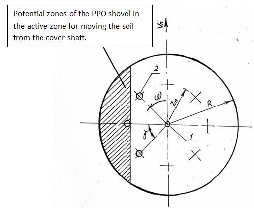
case, it will always adhere to the soil [6, 15] (Fig. 2).
Fig. 2. Scheme for determining the distance rp of the installation of the stars from the center of
rotation.
According to Figure 2, the number of stars can be determined through the following
Equation 9:
Zn = 2π/γ (9)
where, γ - central angle between the radii drawn through adjacent stars.
Angle γ from Fig. 2 can be seen as 45o.
4E3S Web of Conferences 284, 02011 (2021) https://doi.org/10.1051/e3sconf/202128402011
TPACEE-2021
To increase the adhesion of the blade to the soil and before sliding rotation, it is
necessary that one starter is inside the cover shaft. Taking all this into account, the optimal
distance of the installation of the pivots 2 from the center of rotation was chosen equal to R
> rn > R/2, where R is the radius of the outer diameter of the working body.
Substituting the value of γ into Equation 9, we derive the number of stars:
Zn = 2 x 180o/45o = 360o/45o = 8
4 Conclusions
The performance indicators of the rotary working body largely depend on its kinematic
mode of operation, the number of knives, dumps and soil picks. The destruction of weeds
and loosening of the soil in the root zone and the movement of the required volume of soil
towards the row spacing is provided at λ = 1.6-1.8 and Zn = Zh = 8 pcs.
As a result of the experimental studies, it was found that eight stars fixed under the disk
at a distance from the center of rotation equal to R > rn > R/2 created an additional moment,
which caused the rotation of the rotary working body with minimal sliding and slipping,
and also made it possible to increase the removal of soil from the covering zone.
References
1. F. M. Kanarev, Mechanical engineering, 140 (1983)
2. G. N. Sineokov, I. M. Panov, Mechanical engineering, 328 (1977)
3. V. Melikhov, V. Yuzbashev, Mechanization and Electrification of Socialist
Agriculture, 2, 20-22 (1977)
4. V. A. Yuzbashev, Studying the interaction of rotary working bodies with previously
loosened soil, 78, 43-48 (1994)
5. V. S. Rynkevich, Investigation of the nature of soil deformation during deep cutting
with a knife in a vertical plane, 87, 17-26 (1997)
6. V. N. Tkachev, Mechanical engineering, 9, 5-17 (2001)
7. V. V. Usov, V. G. Ivashchenko, Mechanical engineering, 7, 40-68 (2000)
8. I. S. Sinyagovskiy, Strength of materials, 152-203 (1998)
9. A. A. Akhmetov, M. A. Allanazarov, Mechanization of cotton growing, 10, 4-5 (2010)
10. N. Ch. Namozov, D. A. Kodirova, M. I. Usmonova, International journal of scientific
& technology research, 9(03), 5491-5493 (2020)
11. S. Islamov, N. Namozov, M. Saidova, D. Kodirova, In E3S Web of Conferences, 244,
03028 (2021)
12. B. Abdullaev, R. A. Kulmatov, A. A. Kist, Industrial Laboratory (USSR) (English
translation of Zavodskaya Laboratoriya), 54(7), 710-713 (1989)
13. N. Kulmetov, I. Gorlova, Mechanization of Cotton Research, 11, 10 (2009)
14. I. Gorlova, Mechanization of Cotton Research, 8, 12 (2010)
15. I. Gorlova, Mechanization of Cotton Research, 10, 13-14 (2013)
16. J. M. Bennett, N. P. Woodhouse, T. Keller, T. A. Jensen, D. L. Antille, Journal of
Cotton Science, 19(2), 225-249 (2015)
17. W. B. Faulkner, J. D. Wanjura, R. K. Boman, B. W. Shaw, C. B. Parnell, Applied
Engineering in Agriculture, 27(4), 497-506 (2011)
5You can also read