Research on Application in Intelligent Vehicle Automatic Control System - IOPscience
←
→
Page content transcription
If your browser does not render page correctly, please read the page content below

Journal of Physics: Conference Series

PAPER • OPEN ACCESS

Research on Application in Intelligent Vehicle Automatic Control System
To cite this article: Yinghui Wang et al 2021 J. Phys.: Conf. Ser. 1828 012046

View the article online for updates and enhancements.

                               This content was downloaded from IP address 46.4.80.155 on 23/09/2021 at 11:45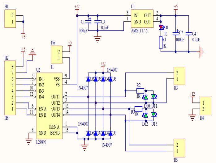
ISAIC 2020                                                                                                      IOP Publishing
Journal of Physics: Conference Series                         1828 (2021) 012046          doi:10.1088/1742-6596/1828/1/012046

Research on Application in Intelligent Vehicle Automatic
Control System

                     Yinghui Wang1,* ,Wenfu Sun1 and Yong Lu 2
                     1Institute
                               of Science and Technology, University of Sanya, Sanya572000, Hainai,
                     China
                     2
                       College of Power and Energy Engineering, Harbin Engineering University, Harbin
                     150001, China
                     *E-mail: 2315630585@qq.com

                     Abstract.The traditional motor bridge circuit always has short circuit problems, and the smart
                     car needs to be controlled by wire or remote control equipment. In order to study the
                     application of automatic control technology in smart cars. Using the smart car model and
                     simulation to study the smart car control system, with the mobile phone as the remote wireless
                     control terminal, the smart car uses bluetooth communication and MCU as the intermediate
                     bridge, the smart car achieves automatic direction control, voice control, gravity induction
                     control, automatic tracking, automatic anti-collision and other functions. The motor circuit
                     system is optimized by Simulation and experiment. It replaces the previous wired control and
                     remote control equipment control, and effectively reduces the cost of equipment.

1.Introduction
With the development of society, more and more cars have brought a series of urgent problems to
cities, including traffic accidents, road congestion, traffic equipment failures, etc. In this environment,
the development of smart transportation and smart cars has become the future trend [1]. The
autonomous control function of the smart car combined with the Internet of Vehicles will promote the
global transportation and transportation network system to achieve high efficiency and low accident
rate, so that the development of human transportation will reach a new level [2]. With the development
of electronic technology and the Internet, higher requirements have been put forward for road
recognition and autonomous control of smart cars [3]. The main research directions of vehicle
networking technology in intelligent vehicle systems include full-body attitude monitoring, intelligent
active collision avoidance, and automatic driving [4].
    The thesis is based on automatic control technology, through proteus simulation principle and
intelligent car model, to study the design and functional application of intelligent car control system.
To simulate and optimize its structure, to find out the influencing factors of automatic control
technology in road recognition, and analyze its advantages in car driving, thus to improve the
performance of smart cars.

2.Function
The overall design of the intelligent car control system is divided into six modules, including the main
control module, input module, output module, body structure module, and road automatic
identification module. The mainly control module analyzes and processes the received front-end

              Content from this work may be used under the terms of the Creative Commons Attribution 3.0 licence. Any further distribution
              of this work must maintain attribution to the author(s) and the title of the work, journal citation and DOI.
Published under licence by IOP Publishing Ltd                          1
ISAIC 2020 IOP Publishing
Journal of Physics: Conference Series 1828 (2021) 012046 doi:10.1088/1742-6596/1828/1/012046
information, channel data and smart car speed data through the MCU. The input module is the front
end of receiving information composed of tracking sensor, infrared sensor, gravity sensor, speed sensor,
radar, etc. It transmits the received environmental information and distance data to the control terminal.
Output module includes mobile phone client and Bluetooth module. The Bluetooth module receives
the work instruction sent by the mobile phone, and sends the work instruction to the single-chip MCU,
MCU judges the content of the instruction. It also executes the corresponding function module
according to the judgment. The body structure module mainly refers to the design of the body, it
includes the steering gear control module, which drives the servo motor to complete the steering
control of the smart car; the motor drive module, which drives the DC motor to play a key role in the
car, which can control the acceleration and deceleration of the car. The auxiliary debugging module
can be used for online debugging and status monitoring. The button module can change the speed and
parameters of the smart car. The paper will introduce the key modules in detail.
3.Main Module Design of the System
3.1 Motor Drive Simulation Analysis
The most widely used drive circuit of the motor is the h-type full-bridge circuit, which can easily
realize the four-quadrant operation of the DC motor, corresponding to forward rotation, forward
braking, reverse rotation, and reverse braking [5].As shown in Figure 1, during the movement of the
smart car, the motor needs to be constantly switched between the four quadrants, that is, between
forward rotation and reverse rotation, that is, S1, S2 are turned on and S3, S4 are turned off , S1, S2
are open and S3, S4 are open, and both states are open.
Figure 1. Full bridge motor circuit diagram.
In this case, two sets of control signals are theoretically required to complement each other [6].
However, in practice, there is a certain time error in the opening and closing of the switch [7], and the
absolutely complementary control logic will inevitably lead to a short circuit between the upper and
lower bridge arms [8]. In order to avoid direct short circuit and ensure coordination and
synchronization between switch actions, it is theoretically necessary to invert the two control signals,
but in practice there must be sufficient no-load time difference. The direct short circuit is easy to heat
the switch tube and burn it badly. At the same time, it increases the energy loss of the switch tube and
wastes the precious energy of the intelligent car.
Traditionally, the switch loss and heating can be reduced by adding a delay link device to the
hardware circuit [9]. However, the complexity of the circuit will be increased, and problems such as
equipment failure and instability will occur [10]. In order to solve this kind of hardware problem, it is
realized through software programming during design. Inserting the delayed link program when the
switch is suddenly reversed, and turn on the switch that should be turned on after the switch is closed,
as shown in Figure 2. Every time the switch changes direction, it will not switch the direction
immediately. It firstly turns off the switch for a period to make it completely closed, then it turns on
another switch tube. The closing time is realized by a software delay controlled by the MCU.
2ISAIC 2020 IOP Publishing
Journal of Physics: Conference Series 1828 (2021) 012046 doi:10.1088/1742-6596/1828/1/012046
Begin
Start the
driver
No
Turn to
Yes
Reversing
End
Figure 2. Flow chart of the software controls the motor.
The connection time of motor bridge arm can be corrected by increasing the delay between two
control signals of upper and lower arms (Figure 3).
Figure 3. Figure of upper and lower bridge arms.
The system uses L298N as the drive module, which can directly drive 3-35V DC motors [11]. As
shown in Figure 4, IN1, IN2, IN3, IN4 are L298N logic input ports, UT1, OUT2, OUT3, OUT4 are
output ports. Because the output voltage is not stable enough, IN4007 diodes are used for voltage
limiting protection. They Make the output voltage of H3 and H5 reach close to ideal voltage value.
Figure 4. L298N drive circuit diagram.
After the smart car recognizes the road conditions, the steering control algorithm is introduced to
3ISAIC 2020 IOP Publishing
Journal of Physics: Conference Series 1828 (2021) 012046 doi:10.1088/1742-6596/1828/1/012046
control the smart car and guide the direction of movement of the car. The actuator of the steering
system of the smart car is a steering gear, which uses an adjustable PWM square wave to control the
steering of the steering gear, that is, different duty ratios correspond to different angles, and the
steering gear rotation angle is in a linear relationship with the duty ratio. The steering control of the
steering gear uses PID control to control the steering of the steering gear. The formula is:
Δpwm = Kpe1+ Kd(e1 - e2) (1)
ΔPWM represents the output servo PWM increment, e1 and e2 respectively represent the current
and last position offset, Kp and Kd are the proportional coefficient and the differential coefficient
respectively.
3.2 Bluetooth Module
The single-chip MCU directly controls the Bluetooth module. The bluetooth selected in the design can
control the distance of the car up to about 50 meters. During the transmission of instructions, the
intelligent car can be controlled in real time, it avoids the delay of work tasks since the car cannot
receive data in real time [12]. Seting the character string in the MCU program. The given MCU and
the Bluetooth module receive and send the same character string. When the Bluetooth module
transmits the character to the MCU, the MCU recognizes it, when the set character is recognized. The
MCU generates an interrupt and executes the corresponding program.
When the bluetooth mode of the mobile phone is turned on, and the bluetooth of the car is also
turned on, the automatic search function of the hand will recognize the bluetooth that has been started
around and conduct pairing. Once the pairing is successful, the Bluetooth module will send characters,
then the bluetooth module of the MCU will receive the corresponding characters, the MCU will
process and perform the corresponding functions. For example, the car forward function can be
realized: press the button of "forward", and the start character "A" will be sent. The Car's Bluetooth
module will receive the character "A" and send it to the MCU for processing. The MCU will execute
the interrupt program corresponding to the character "A". When the button is released, the character
"F" is sent. backward, left, right, stop, send the corresponding characters are: "B", "C", "D", "F", the
implementation method is the same as the principle of forward. When the left turn and right turn
buttons are released, the operation mode of the trolley is not to stop immediately, but to continue
forward in the positive direction after turning. At the same time, the Bluetooth module can also
cooperate with voice control to set the sentence that the car is going to say, then it realizes the
automatic control of the smart car. The specific process is shown in Figure 5.
4ISAIC 2020 IOP Publishing
Journal of Physics: Conference Series 1828 (2021) 012046 doi:10.1088/1742-6596/1828/1/012046
Click the "Bluetooth
Connection" button
No
Whether to turn on To prompt
Yes
Bluetooth
pairing
"Forward" "Back" "Turn Left" "Turn right"
"Stop" button
button button button button
Release
Release Release Release
Press Press Press Press Press
Send character Send character Send character Send character Send character
A B C D F
Figure 5. Flow chart of Bluetooth module control.
4.Automatic Tracking Module
Smart car has automatic tracking function, automatic tracking has three modes, through the button to
switch mode. Mode 1: Tracking indicator light is on; Mode 2: Obstacle avoidance indicator light is on,
indicating that this is the obstacle avoidance mode; Mode 3: Tracking light and obstacle avoidance
indicator light are on at the same time, indicating that the tracking and obstacle avoidance are realized
at the same time. The test run of the car model shows that the time of automatic tracking completion
can be set by counting. As shown in Table 1.
Table 1. Automatic tracing status.
Counting Timing Car track
interval time
1-20 2s Go forward
21-30 1s Turn right
31-40 1s Stop
40-60 2s Go forward
61-70 1s Turn right
71-80 1s Stop
80-100 2s Go forward
101-110 1s Turn right
111-120 1s Stop
5ISAIC 2020 IOP Publishing
Journal of Physics: Conference Series 1828 (2021) 012046 doi:10.1088/1742-6596/1828/1/012046
121-140 2s Go forward
141-150 1s Turn right
151-160 1s Stop
160-180 2s Go forward
>180 - Stop
5. Smart Car Automatic Anti-collision Design
5.1 Analysis of Anti-collision Principle
The process from taking braking measures to stop the car has a great influence on the design of the
anti-collision device [13]. There are five influencing factors in the process from braking to stop a car:
1) When the driver is aware of the danger, and is ready to take braking measures in his mind.
2) When the driver uses the brake measures, the brake device will affect the braking time.
3) The driver takes braking measures, and the pedal force is gradually increased until the braking
effect is the best.
4) When the driver presses down the pedal, the force will not change for a long time. Currently, the
effect is the best until the vehicle stops.
5) The braking force time when the maximum value of the vehicle decreases to zero after parking is
also the time when the brake pedal under the driver is slowly lifted.
The first four times determine the braking distance of the vehicle, and the automobile anti-collision
alarm system is also directly related to the distance and speed between the two vehicles. The principal
diagram of vehicle collision is shown in Figure 6. In the figure, car B and car A keep a distance D, and
the driver drives the car at a certain speed. When they are in danger respectively, the two cars take
braking measures. The speeds of the two cars after braking are VA and VB, and the corresponding
distances after deceleration are DA and DB. If the distance between two cars is not enough, it will often
cause traffic accidents.In order to ensure the safety of A and B during service braking, the following
requirements need to be met to maintain a safe driving distance between the two vehicles when
braking: DB+d2 is less than or equal to d1+DA. After braking, the speed of the two cars must be
satisfied: when the distance between the two cars is d, VA is greater than or equal to VB, otherwise the
two cars will collide.
Figure 6. Schematic diagram of car collision.
5.2 Automatic Anti-collision Module
In the collision system designed by proteus simulation and smart car model, when the distance from
the obstacle to the smart car is lower than the safety range of the set value [14], it will actively perform
the collision avoidance function [15]. It mainly has functions such as detection distance, system
information processing, and system alarm. The MCU processes the detected distance data, and
compares the data information with the set dangerous alarm distance, determines whether to issue an
alarm command, and controls whether the collision avoidance system alarms. The alarm module is an
6ISAIC 2020 IOP Publishing
Journal of Physics: Conference Series 1828 (2021) 012046 doi:10.1088/1742-6596/1828/1/012046
audible and visual alarm device, which reminds by both voice and light flashing. And the distance
between the vehicle and the obstacle is displayed on the display.
6. Conclusions
The paper focuses on the actual needs and problems of smart cars, and uses simulation and smart car
models to complete the design of the smart car control system. The functions of the smart car have
been debugged and all functions can be realized. The smart car can move forward, backward, turn left,
turn right, climb hills, go downhill, and turn. It also has obstacle avoidance and anti-collision alarm
functions. Research and development can be continued on this basis, and the system has good
scalability and stability.
Innovation points of system design:
1.In the design of the motor, it breaks through the traditional form of bridge circuit, adds the delay
time program to the software program, corrects the delay time of the upper and lower bridge arm,
effectively changes the short circuit defect, and uses an adjustable PWM square wave to control the
steering gear, which saves the cost of the motor.
2.The smart car is no longer controlled by the previous wired control or its own remote-control
device. It uses the mobile phone network and Bluetooth to design, realizes the control of the smart car
through the wireless smart phone combined with Bluetooth, and the car automatically performs
corresponding actions and automatically avoids Obstacle and tracking. The automatic control
technology has been practically applied and verified on the smart car model.
Acknowledgments
This paper is supported by scientific research in colleges and universities of Hainan Province (No:
Hnky2019-67). This paper is supported by scientific research in University of Sanya
(No:USY18YSK058) and National Natural Science Foundation of China (No:619QN244).
Reference
[1] Hu K, Wu J and Liu M 2018 Modelling of EVs Energy Consumption from Perspective of Field
Test Data and Driving Style Questionnaires Journal of System Simulation 30(11) 4106-14
[2] Li K, Dai Y and Li S, et al. 2017 State -of -the -art and technical trends of intelligent and
connected vehicles Journal of Automotive Safety and Energy 8(1) 1-14
[3] Ji J, Li Y and Zheng L, et al. 2010 Integrated Control of Longitudinal and Lateral Motion
forAutonomous Vehicle Driving System China Journal of Highway and Transport 23(5) 119-126
[4] Mou R, Wang C 2019 Study on Pedestrian Vehicle Conflict Severity Grade Based on Cloud
Theory Journal of Chang,an University (Natural Science Edition) 39(6) 99-106
[5] Qiu Z, Ruan J and Huang D, et al. 2015 Mechanical fault diagnosis of high voltage disconnector
based onmotor current detection Proceedings of the CSEE 35(13) 3459-66
[6] Wang Q, Chen J and Wang T, et al 2020 High Efficiency Single Phase Full Bridge Soft Switching
Rectifier Acta Electronica Sinica 48(6) 1244-8
[7] Hu X, Liu Y and Niu Z 2020 Unqualified Rate Control of Front Wheel gnment Parameters and
Tolerance Optimization Design Machinery Design & Manufacture 350(04) 123-7
[8] Zhang D, Cui Y and Chen C 2020 An Adaptive Routing Method for High-Speed-Road Scenario of
the Internet of Vehicle Acta Electronica Sinica 1(1) 172-8
[9] Huang J, Yu Z and Chen R 2018 Analysis of fuzzy direction control in intelligent vehicle system
Application of Electronic 44(9) 21-3
[10] Song X, Zhou N and Huang Z et al 2017 An improved RRT algorithm of local path planning for
vehicle collision avoidance Journal of Human University (Natural Sciences) 44(4) 30-7
[11] Li H, Lu P, Li M 2019 Design and Implementation of Virtual Reality Training System of a Diesel
Engine Computer Simulation 36(12) 267-271
[12] Chen C 2018 Neural network based navigation path recognition model of intelligent vehicle
Modern Electronics Technique 41(11) 124-8
7ISAIC 2020 IOP Publishing
Journal of Physics: Conference Series 1828 (2021) 012046 doi:10.1088/1742-6596/1828/1/012046
[13] Ni J and Liu Z 2016 The model of lane change based on driver decision making mechanism
Transportation System Engineering and Information 16(11) 58-63
[14] Ma C, Zhang Sand Ma Z, et al 2018 Nonlinear Negative Binomial Regression Model of Express
way Traffic Accident Frequency Prediction China Journal of Highway and Transport 31(11)
176-185
[15] Sun C, Xin F 2016 An Overview of the Conflict Indicators between Vehicles and Pedestrian
Journal of Transport Information and Safety 2(34) 9-16
8You can also read