Research Report 2021 - ZHAW
←
→
Page content transcription
If your browser does not render page correctly, please read the page content below
Research Report 2021

Zurich University
of Applied Science www.zhaw.ch/engineering
CFD simulation illustration of a heat pipe with
100 °C heating temperature and forced air
cooling via aluminum cooling fins.
Research Report 2021 Institute of Computational Physics

Introduction
Computational Physics & Artificial Intelligence
We are experiencing an extremely active research period in the field of artificial intelligence. Some prac-
tical applications are already being used extensively by large corporations, while for small and medium-
sized enterprises the benefits of this new technology are not yet clear. The Centre for Artificial Intelli-
gence (https://www.zhaw.ch/cai/) is currently being established at ZHAW. We wish them a successful
start and are looking forward to future close collaboration.
What significance does this development have for ICP? What are our projects on this topic? And what
could be our contributions in this emerging field in the future? Currently there are two projects at ICP.
They are described in detail on pages 29 and 41. In section 5, Evelyne Knapp lays the foundation for
further discussions on the merging of computational physics and artificial intelligence. The current state
of research is summarized and the questions posed above are organized. At ICP, we are currently
expanding partner networks and considering promising applications for industrial partners. All should
actively participate in the discussion.
The COVID-19 pandemic has demanded a lot from us and has drastically changed our working envi-
ronment. I would like to thank everyone for the extraordinary efforts that have been made at ICP. We
have found new ways of productive collaboration, even remotely. But we also long to meet again regu-
larly in person. I would like to call on you all to play an active role in shaping this return. In the foreseeable
future we will likely need to continue experimenting with hybrid meetings and perhaps with forms of
virtual social sharing. Maybe we need to look closely at shortfalls and deficits that have arisen during
the time of working from home. Maybe unconventional and spontaneous actions are needed. Let us
cultivate a healthy optimism and good human contact. In this sense, a sincere "Welcome Back!" in the
hope that we can meet again soon at our Winterthur location.

Andreas Witzig,
Head of Institute ICP

Zurich University of Applied Sciences I www.zhaw.ch
Research Report 2021 Institute of Computational Physics

Table of Contents
Introduction I

Table of Contents II

1 Multiphysics Modeling 1

 PM-ASPV: Simulation-Based Assessment of Magnetic Control of a Free-Floating
 Magnet ................................................................................................................................ 2
 Powder Coating: Simulation-Based Prototype Development of Novel Powder
 Coating Nozzles .................................................................................................................. 3
 Development of a Tubular Resonator Sensor Platform for Inline Process
 Fluid Monitoring ................................................................................................................... 4
 Simulation-Based Calibration of Infusion Systems ............................................................. 5
 CFD Modelling of Droplet Impact into Resting Fluid ........................................................... 6
 Development of a Multi-Physics Solver for Powder Coating Processes with
 Arbitrarily Moving Pistol....................................................................................................... 7
 Thermophoretic Force on Suspended Particles ................................................................. 8
 Three-Dimensional Powder Snow Avalanche Modeling ..................................................... 9
 3D Pore Microstructures and Computer Simulation: Effective Permeabilities
 and Capillary Pressure during Drainage in Opalinus Clay ................................................ 10
 Model Based Optimization of MIEC SOFC Anodes .......................................................... 11
 Massive Simultaneous Cloud Computing (MSCC) for Data Driven Optimization
 of SOFC Electrodes .......................................................................................................... 12
 Model-Based Development of Ceramic Filters for Masks, Air Purifiers and
 Air Conditioning Systems .................................................................................................. 13
 Efficient Thermal Model for the Precise Prediction of Welding Times for
 Infrared Welded Plastic Pipes ........................................................................................... 14
 Development of a New Type of IR Heating Concept for Contactless Welding of
 Plastic Pipes ...................................................................................................................... 15
 Effective Thermal Conductivity and CFD Implementation of a Heat Pipe ........................ 16
 Simulation of the Envelope Temperature of a Hot Air Balloon ......................................... 17
 Lifetime of Gold Contact Components under Adhesive Wear Loading ............................ 18
 Enhanced Peridynamics Capability in Mechanical Faillure Prediction ............................. 19
 Coupling XFEM and Peridynamics for Brittle Fracture Simulation – Part I:
 Feasibility and Effectiveness ............................................................................................. 20
 Coupling XFEM and Peridynamics for Brittle Fracture Simulation – Part II:
 Adaptive Relocation Strategy ............................................................................................ 21
2 Electrochemical Cells and Microstructures 22

 Macro-Homogeneous Models for Organic Redox Flow Batteries .................................... 23
 DeMaPEM: Development and Marketing of Proton Exchange Membrane
 Fuel Cells for Transport Applications ................................................................................ 24

Zurich University of Applied Sciences II www.zhaw.ch
Research Report 2021 Institute of Computational Physics

 3-D model of Water and Heat Transport in PEMFCs during Evaporative
 Cooling and Humidification ............................................................................................... 25
 A New Thermodynamical Framework for Improved Aqueous Flow Battery Modelling .... 26
 Microscale Modelling Study of Coupling Mass Transport with Convective Flow
 in Porous Electrodes for the Application in Redox Flow Batteries .................................... 27
3 Organic Electronics and Photovoltaics 28

 Silicon Solar Cell Parameter Estimation by a Convolutional Neural Network
 Trained on Simulated Data ............................................................................................... 29
 Experimental Validation of an Electro-Thermal Small-Signal Model for
 Large-Area Perovskite Solar Cells .................................................................................... 30
 Dynamics of Charge Transfer States in Organic Semiconductor Devices:
 A Combined Experimental and Simulation-Based Approach (CTDyn) ............................. 31
 New Tools for Characterizing Quantum-Dot Displays ...................................................... 32
 Investigating Charge Transport in Organic Semiconductors with Electrochemical
 Methods and Modelling ..................................................................................................... 33
 All-Organic Gap-Free Terahertz Photonics ....................................................................... 34
 Hardware-Software Integration and Validation of a Compact THz System ...................... 35
4 Sensors and Measuring Systems 36

 Detecting Nanoparticles in Complex Environments .......................................................... 37
 Portable Device for Early Diagnosis of Lymphedema ...................................................... 38
 Design and Development of Artificial Skin Models for Tactile Sensing Applications ........ 39
 Measurement Technology for Decentralized Energy Systems ......................................... 40
 4.5 Artificial Intelligence (AI) Heat Pump Controller ................................................................ 41
5 Computational Physics and Artificial Intelligence 42

Appendix 44

 A.1 Student Projects ................................................................................................................ 44
 A.2 Scientific Publications ....................................................................................................... 45
 A.3 Book Chapters .................................................................................................................. 48
 A.4 Conferences and Workshops ............................................................................................ 48
 A.5 Teaching ........................................................................................................................... 50
 A.6 ICP Spin-Off Companies ................................................................................................... 52
 A.7 ICP Team .......................................................................................................................... 55
 A.8 Location ............................................................................................................................. 56

Zurich University of Applied Sciences III www.zhaw.ch
Research Report 2021 Institute of Computational Physics

1 Multiphysics Modeling
Multiphysics modeling is a powerful tool for exploring a wide range of phenomena, coupling flow, struc-
ture, electro-magnetic, thermodynamic, chemical and/or acoustic effects. The past decades have been
a period of rapid progress in this area. In fact, the possible range of applications has been widely ex-
panded and numerical methods have become increasingly sophisticated and adapted to exploit availa-
ble computational resources. Today, detailed physical-chemical models combined with robust numerical
solution methods are almost a necessity for the design and optimization of multifunctional technical
devices and processes.
At the ICP, we perform applied research in the field of multiphysics modeling and develop finite element,
as well as finite volume simulation software.
Our extensive experience in numerical analysis, modeling and simulation allows us to successfully apply
simulation-based optimization in many fields. We are familiar with a wide range of governing physical
equations and find numerical solutions even when the effects are closely interrelated. We also develop
single-purpose numerical tools tailored to the specific needs of our partners, and we use commercial
software where it is more suitable.
Our specialties in this context include the application, extension and development of coupled models
using our own finite element software SESES, the fluid dynamics software OpenFoam (open source)
and commercially available products such as COMSOL.

 G. Boiger M. Boldrini D. Brunner V. Buff S. Ehrat T. Hocker

 L. Holzer M. Hostettler L. Keller V. Lienhard P. Marmet Y. Safa

 D. Sharman B. Siyahhan J. Stoll A. Zubiaga

Zurich University of Applied Sciences 1 www.zhaw.ch
Research Report 2021 Institute of Computational Physics

 PM-ASPV: Simulation-Based Assessment of Magnetic Control of a
 Free-Floating Magnet
A number of discretized controllable magnets are set up circular in a 2D plain. A dipole or spa-
tially extent magnet is assumed in the center. To achieve stability without touching the “walls”,
required forces on the dipole must always point towards the center. The required force field is
calculated and mapped for all possible dipole positions. The respective local magnetic field
around the magnets is calculated analytically and simulated in a transient control loop to affirm
stability. The project is ongoing and results look promising.

Contributors: A. Zubiaga, V. Lienhard, M. Boldrini, V. Buff, G. Boiger
Partner(s): Peter Meyer & Co. AG
Funding: Innosuisse
Duration: 2019–2021

There is more than one way to keep a magnetic di- This mapping is done for each point in space and
pole or spatially extent magnet in a stable position. time for each magnet and should lead to a stable con-
However, Earnshaw’s Theorem forbids any stable trol loop. Torque considerations on the dipole/magnet
configuration using permanent magnets only, stating and gravity effects will be subsequently included.
that at least one DoF must be fixed or controlled. Re-
search was conducted on various possibilities around
this restriction. In magnetic engines this is done by
fixating the rotation axis and circular rotating mag-
netic fields. This requires the rotor to either follow or
precede the magnetic field leading to synchronous-
or asynchronous-motors. While this might be ex-
plored in a later project state, the focusing on a full
control-loop is considered more valuable. Based on
the Ampère-Dipole model, required fields and forces
were assessed by analytical and simple prediction
models using excel and Berkley-Madonna in a first
step.

 Figure 2: The magneto static force (red arrow) acting on the central
 magnet exerted by the magnetic field (black curves).

 The simulation-based proof of concept in 2D has
 been established and inclusion and verification of fur-
 ther, previously neglected effects is in the process.
 Leveraging to 3D is still planned but has proven more
 challenging than initially expected. Experimental ap-
 proaches from this groundwork have been estab-
 lished and further development focuses on experi-
 mental verification from now on.

Figure 1: Exemplary set up of four control magnets and free-floating
magnet. The arrows show the direction and magnitude of the mag-
netization, the streamlines represent the resulting magnetic field.

More elaborate analytical and numerical models
were implemented in a combination of MATLAB and
COMSOL. A recovery central force is implemented
that keeps the central magnet floating between the
control magnets. The respective force field is calcu-
lated and mapped to the 2D area. The magnetic field
required is then calculated analytically and numeri-
cally and mapped on the discretized control magnets.

Zurich University of Applied Sciences 2 www.zhaw.ch
Research Report 2021 Institute of Computational Physics

 Powder Coating: Simulation-Based Prototype Development of
 Novel Powder Coating Nozzles
Through the development of an extensive numerical Euler-Lagrangian simulation model, highly
efficient nozzle geometries were developed. The simulations were validated on measurement
series covering several thousand experiments. The new nozzles which resulted out of the project
achieved an increase in coating efficiency by over 15%.

Contributors: G. Boiger, M. Boldrini, V. Lienhard, B. Siyahhan, V. Buff
Partner(s): Wagner International AG
Funding: Innosuisse
Duration: 2017–2020

In the course of this project, an extensive numerical achieve a coating efficiency increase of 23-31% for
Euler-Lagrangian simulation model for powder coat- the most commonly used parameter ranges.
ing applications was developed and comprehensively
validated. The model couples all relevant physical in- Literature:
fluencing factors such as electrostatic field strength, [1] Boiger, G.; Boldrini, M.; Lienhard, V.; Siyahhan, B.; Khawaja, H.;
air flow, particle size distribution, particle - substrate Moatamedi, M., 2019. Multiphysics Eulerian-Lagrangian Electro-
 static Particle Spray- And Deposition Model for OpenFoam® and Ka-
interaction, particles - particle interaction and gravita- leidoSim® Cloud-Platform (2020). Int.Journal of Multiphysics. 14(1),
tion. The solver was validated by several thousand pp. 1-15. DOI: 10.21152/1750-9548.14.1.1
 [2] Boiger G., Bercan S.; Lienhard, V.; 2020. Advancing the Valida-
coating experiments and their evaluation. With this tion and Application of a Eulerian-Lagrangian Multiphysics Solver for
new numerical model, a powder coating process can Coating Processes in Terms of Massive Simultaneous Cloud Com-
 puting. Multiphysics 2020. 15th International Conference of Multipys-
now be quantified in a previously unattainable quality, ics, Online, 10-11 December 2020. International Society of Mul-
both quantitatively and qualitatively. This new numer- tiphysics. ISSN (online) 2409-1669.
ical analysis method has already provided far-reach-
ing insights into the interrelationships between pro-
cess parameters and coating results.

Fig. 1: Simulation results in comparison to measurements on a U-
profile substrate. Example for qualitative correspondence of simu-
lated (top) and measured (bottom) coating patterns. Here the front
side of an A4-plate substrate was coated at a pistol-substrate-dis-
tance D=20cm, while applying an airflow rate Q=3m3/h and effective
voltages Ueff of 30kV, 40kV and 50kV respectively. It can be seen
that the main qualitative coating-pattern-features, as well as trends
of simulations and experiments match well, [1].

Based on these simulation results and extensive
measurements, it was possible to design a set of new
internal geometries for the nozzle part of the pistol.
These new nozzle types, while in a prototype stage,
showed the potential to increase process metrics
such as homogeneity and coating efficiency. From
the set of suggested new geometry types, two were
selected by the customer for further investigation.
Both selected types showed an increase of the coat-
ing efficiency by over 15% for the complete parame-
ter range.
Through further investigation and development on
the selected nozzles, the design was improved to

Zurich University of Applied Sciences 3 www.zhaw.ch
Research Report 2021 Institute of Computational Physics

 Development of a Tubular Resonator Sensor Platform for Inline
 Process Fluid Monitoring
Monitoring fluid properties such as viscosity is crucial in many industrial processes. For sanitary
processes, cleanability is a crucial factor. A tubular non-intrusive resonant sensor was devel-
oped to measure the viscosity in the process line, avoiding any flow obstructions and cleanable
in place using industry-standard processes. To develop these sensors, a comprehensive, scal-
able model was developed to describe the fluid-structure interaction of the fluid with the reso-
nator.

Contributors: D. Brunner, G. Boiger
Partner(s): Rheonics GmbH
Funding: Innosuisse, Rheonics GmbH
Duration: 2018–2021

In this study, a tubular torsional resonator was devel-
oped. Its resonance was driven and sensed using
electromagnetic transducers.
The operating principle of the sensor is based on the
excitation of a torsional mode, and subsequent
measurement of the resonant response. The damp-
ing and resonance frequency are determined from
the response signal. Resonance frequency and
damping are then related to the fluid’s viscosity.
A comprehensive numerical model of a tubular reso-
nator has been developed and validated. The sensor
used for the validation study had an inner diameter of
5.25 mm (1). For most industrial processes, larger
tube diameters are required. Therefore, using the
previously validated models, a larger version of a Figure 1: DN20 tubular resonator (left), DN20 tubular resonator op-
 erating in an experimental flow loop.
functionally similar sensor was built and tested. The
larger resonator was based on a 20 mm inner diam-
eter tube, as shown in Figure 1.
The sensor was calibrated, and the calibration veri-
fied, using a series of NIST traceable viscosity refer-
ence fluids. The sensor measured the fluid’s viscos-
ity-density product ρη over a wide range from 1 to
100’000 mPa.s. The measured values of the band-
width divided by the resonance frequency (Γ/f0 ) were
in good agreement with the predictions of the numer-
ical model (see Figure 2), showing the utility of the
model as a development tool for scaling to larger di-
ameter tubes.

 Figure 2: Bandwidth divided by the resonance frequency (Γ/f0) vs.
 the viscosity density product ρη for different fluids and the numerical
 prediction.

 Source:
 D. Brunner, J. Goodbread, K. Häusler, S. Kumar, G. Boiger, H. Kha-
 waja, Analysis of a Tubular Torsionally Resonating Viscosity-Density
 Sensor, MDPI Sensors, 2020, 20 (11), 3036.
 https://doi.org/10.3390/s2011

Zurich University of Applied Sciences 4 www.zhaw.ch
Research Report 2021 Institute of Computational Physics

 Simulation-Based Calibration of Infusion Systems
Infusion systems enable the continuous administration of drugs in liquid form. For medical op-
eration it is necessary to maintain an exact volume flow, which is achieved by using peristaltic
pumps. However, the calibration of such pumps requires complex measurements, which impairs
the broad application of such systems. By means of a simulation model, the fluid dynamic be-
havior of the pump and infusion system shall be modelled in order to enable a more efficient
calibration, and to apply different configurations of the product.

Contributors: M. Hostettler, G. Boiger
Partner(s): Codan Argus AG
Funding: Innosuisse
Duration: 2019–2021

When using medical infusion systems, a high degree
of accuracy regarding the amount of injected medica-
tion is required. Peristaltic pumps, among others, are
used to set a desired volume flow. Since very small
volume flows are required, direct volumetric determi-
nation of the flow rate is not possible. The flow rate
must be determined from the system and pump pa-
rameters. For the necessary calibration of the pump,
however, individual and extremely extensive meas-
urements are necessary, which considerably limit the
efficient use of such devices.

 Figure 2: Model of the infusion system with pump and various com-
 ponents.

 Within the scope of the project, comprehensive ex-
 perimental measurements are used to individually
 characterize the behavior of all flow-carrying compo-
 nents. Various numerical models (from simple one-
 dimensional methods to detailed CFD simulations in-
 cluding fluid-structure coupling) are investigated and
Figure 1: Different components of an infusion system (from left to
right: flow controller, drop-counter, filter and tubing). compared with measurements to characterize the
 pump and the viscoelastic behavior of the peristaltic
In the present work, the basic flow behavior in the tube.
hose system and peristaltic pump is investigated and Based on the measured data of the individual com-
a model is developed to make the calibration of such ponents and the findings from the characterization of
systems more efficient. the pump and peristaltic tube, the flow dynamic
With this model, any configuration of the components model of the infusion system is developed (see Fig-
installed in the infusion system (see Figure 1) can be ure 2), and is validated by means of specific experi-
better realized and a broader application of the prod- ments.
uct is enabled.

Zurich University of Applied Sciences 5 www.zhaw.ch
Research Report 2021 Institute of Computational Physics

 CFD Modelling of Droplet Impact into Resting Fluid
When transporting a vial filled with liquid, the fluid is exposed to external vibrations from the
transport vehicle. These vibrations cause motion and therefore shear stresses and pressure
forces in the fluid. When it comes to pharmaceutical fluids, it is essential to understand these
shear and pressure conditions because they can lead to the degradation of the drug. In certain
conditions, droplets can be formed. The presented work investigates the re-impact of such a
droplet into the surface of the fluid and the corresponding shear forces using detailed CFD sim-
ulations.

Contributors: M. Hostettler, D. Brunner, G. Boiger
Partner(s): F. Hoffmann-La Roche Ltd. Basel
Funding: F. Hoffmann-La Roche Ltd. Basel
Duration: 2020–2021

During the transportation of liquid drugs, the mechan- calculated to analyze the probability of occurrence of
ical stress on the fluid has a major impact on the deg- a certain shear load when changing a parameter.
radation of the active ingredient of the drug. Former
studies investigated the vibration-based formation of
wave patterns and wave intensities at the surface of
the fluid inside a transport vial. These waves can lead
to splashing. The present study focuses on the esti-
mation of the shear stress caused by splashing to
gain insight about the relevance of this phenomenon
and to determine the most important influence pa-
rameters.
Thereby, a falling droplet (see Figure 1), which im-
pacts into a surface of a resting liquid in a cylindrical
domain is considered. The impact and immersion of
 Figure 2: Reliability function (probability of occurrence of a certain
the droplet into the surface generates complex agita- shear stress) used to compare the effect from changing one of the
tion of the fluid and leads to the occurrence of shear parameters. Left: marginal effect when varying the falling height;
 Middle: medium effect when varying droplet diameter; Right: large
stresses. These shear stresses depend on parame- effect when varying fluid viscosity.
ters such as falling height, droplet diameter and vis-
cosity of the fluid. The study has shown that peak shear stresses due
 to splashing are much higher (up to 20 times more)
 than for simple wave motion scenarios.
 Further, a significant increase of occurring shear
 stresses and a decrease of the penetration depth can
 be seen when increasing the fluids viscosity. The fall-
 ing height and the droplet diameter have only minor
 influence on the effects.
 An experimental setup has been designed to validate
 the simulation. The test-case has been realized using
 water glycerol solutions of varying viscosity in a 6ml
 vial and methylene blue colored droplets from a nee-
Figure 1: Side view on splashing test-case with falling droplet (top) dle, positioned above the vial. The droplet impact has
and resting fluid (bottom) in a cylindrical domain. Time progresses
from left to right; color indicates magnitude of azimuthal shear stress been captured on video for qualitative comparison of
average. the resulting penetration depth.

Using computational fluid dynamics for a two-phase
system, said degrees of freedom were investigated in
relation to associated shear conditions. Due to the
symmetrical nature of the simulation, the resulting
shear stresses in the fluid phase have been averaged
in azimuthal direction to gain insight into the spatial
region of energy dissipation. Furthermore, based on
a statistical evaluation of the occurring shear stress
values, a reliability function (see Figure 2) has been

Zurich University of Applied Sciences 6 www.zhaw.ch
Research Report 2021 Institute of Computational Physics

 Development of a Multi-Physics Solver for Powder Coating Pro-
 cesses with Arbitrarily Moving Pistol
In the scope of this study, an existing multi-physics solver [1] to simulate particle, flow and elec-
trostatic interactions for powder coating applications has been extended to incorporate moving
coating pistols. Although the existing solver has been validated experimentally [2], the lack of
the capability to incorporate motion of a coating pistol prevented it from directly simulating real
life industrial applications.

Contributors: B. Siyahhan, G. Boiger
Partner(s): internal
Funding: Internal
Duration: since 2020

Powder coating is an environmentally friendly alter- and Fg(N) is the gravity force. This theoretical basis
native to conventional liquid paint-based surface fin- of the existing solver is complemented by the ability
ishing methods, especially suited for thin coatings. It of the coating pistols to move in accordance with any
is employed in a vast range of industrial applications periodic function represented by a Fourier series ex-
(automotive, household appliances, etc.). The pro- pressed in Equation (5):
cess involves a powder cloud transported along with ( ) = 0 + ∑∞ ∞
 =1 cosωt + ∑ =1 sinωt (5)
an air flow within a coating pistol, where an electrical In addition to developing the required motion defini-
corona is formed at the tip of a mounted electrode. tion libraries in OpenFOAM, the particle injection
After passing through the corona, the solid particles model has been updated to accommodate the mov-
are ionized and following their discharge from the pis- ing and multiple pistol cases, and the case set-up and
tol, they coat a grounded substrate upon impact. Due special boundary conditions necessary for the inter-
to the complex interaction involved amongst the fluid facing of a moving region of computational cells to
dynamic, electrostatic forces and the motion of indi- stationary ones have been investigated. The modifi-
vidual powder particles, the process is extremely cations mentioned above allow the simulation of
challenging to simulate. Therefore, in the lack of sci- practical coating applications in real time as depicted
entific tools, the industry has relied mainly on trial- in Figure 1, providing the basis for a scientific tool for
and-error based methods and practical know-how. a priori process design and optimization for powder
To remedy this situation, a multiphysics solver capa- coating applications.
ble of taking into the aforementioned interactions has
been developed [1] within the framework of Open-
FOAM. The solver firstly resolves the electric field
based on the solution of Equation (1):

 2Ψ = − (1)
 0
Where ψ(V) is the electric potential, ρc (C/m3)
 the
charge density ϵ0(F/m) is the permittivity of free
space. Independently, the flow field is also resolved
based on the incompressible continuity and the Na-
vier-Stokes Equations (2) and (3) respectively.
 ⃗ =0
 ⋅ (2)
 ⃗
 Figure 1: Snapshots from a simulation of a car rim being coated with
 ⃗ ⋅
 + ⃗ + ⃗⃗⃗⃗
 ⃗ = − ′ + ⋅ (3) a pistol with combined translational and rotational motion.

Where U(m/s) denotes the fluid velocity, p’(m2/s2) the
pressure normalized by the fluid density νeff(m2/s) the Literature:
viscosity and Su(m/s2) volume source terms. The re- [1] Boiger, G., 2016. Eulerian-LaGrangian model of particle laden
 flows and deposition effects in electro-static fields based on Open-
solved fields can be used to derive the future trajec- Foam (2016). Int.Journal of Multiphysics; 10(2), pp. 177–194(8);
tory of individual powder particles based on the mo- DOI: 10.21152/1750-9548.10.2.177
 [2] Siyahhan, Bercan; Boldrini, Marlon; Hauri, Samuel; Reinke, Nils;
mentum balance Equation (4). Boiger, Gernot Kurt, 2018. Procedure for experimental data assess-
 3
 ment for numerical solver validation in the context of model-based
 ̈ = ̈ = + + (4) prediction of powder coating patterns (2019). Int.Journal of Mul-
 6
 tiphysics. 12(4), pp. 373-392. DOI: 10.21152/1750-9548.12.4.373.
Where mp(kg) is the mass of the particle and xp(m) is
its position, ρp(kg/m3) its density and dp(m) its diame-
ter. The force FD(N) is the flow particle interaction
force, Fel(N) is the electrostatic force on the particle

Zurich University of Applied Sciences 7 www.zhaw.ch
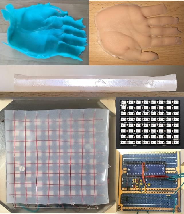
Research Report 2021 Institute of Computational Physics

 Thermophoretic Force on Suspended Particles
This project aims to study the potential of the thermophoretic force to collect particles from the
atmosphere. For that we performed a computational study of the air flow through a collection
chamber, including aerosol particles of diverse size and density and a vertical thermal gradient
that will control the particle deposition in the collection region. A fluid dynamics model is built
to describe the air flow, and the size dependent drag force of the air on the particle is also con-
sidered in full detail. The effect of the particle characteristics (size, thermal conductivity, den-
sity), air flux and turbulences on the deposition process is analyzed prior to perform the first
tests in the physical device.

Contributors: A. Zubiaga, M. Boldrini, G. Boiger
Partner(s): myLab Elektronic Gmbh
Funding: Innosuisse
Duration: 2019–2020

Ambient air can have a sort of suspended or aerosol collection chamber. The real geometry was used for
particles of different origin and sizes. They can be the study and special attention was given to the min-
natural particles like pollen, dust or bacteria and vi- imization of the adverse effect of turbulences once a
ruses, but they can also have human origin like smog steady state flow is reached. Next, the transport of
or soot. The sizes can range from a fraction of a mil- the particles in the air was considered. The particle
limeter down to a nanometer or below. Particulate size dependence of the fluid drag force was carefully
matter is transported by the carrier gas until their dep- taken into account. Finally, the thermophoretic force
osition by buoyancy effects, if their size is large was introduced by adding an extra force on the parti-
enough. Particles smaller than a micrometer, how- cle dependent on a thermal gradient within the fluid.
ever, can remain an indefinite time suspended in the The new force has been shown to strongly enhance
air. This increases the adverse effects that they can the deposition of the suspended particles.
have on our health. Fine and ultrafine particulate mat- The deposition range, however, depends on the ther-
ter can, for instance, enter deep in the lungs and in mal properties of the particles and the particle size is
the cardiovascular system. One obvious way to con- seen to affect it the strongest. Therefore, a non-uni-
trol and limit their malignant effects is by collection for form distribution of the particles within the chamber is
monitoring or other purposes. predicted, with particles of larger size having larger
In this project, we studied the potential of the thermo- deposition range. The conclusions of the study will be
phoretic force to collect particles from the atmos- validated by tests done using the physical device.
phere. We considered first the air flow through the

 Figure: Computational Fluid Dynamics of a
 particle collection chamber. The Flow lines
 show the air flow direction. The point clouds
 represent the incoming particles’ distribu-
 tion and their velocity. The larger particles
 in the right represent a typical deposition
 pattern of the collected particles. The red
 square represents the collection region
 where the thermophoretic force is active. A
 large part of the particles is deposited in the
 few millimeters after entering the deposition
 range because of the thermophoretic force.
 The micrograph in the inset shows a typical
 size of the collected particles.

Zurich University of Applied Sciences 8 www.zhaw.ch
Research Report 2021 Institute of Computational Physics

 Three-Dimensional Powder Snow Avalanche Modeling
It is generally accepted that snow avalanche modeling can be divided into the flow of the heavy
snow-core and the lighter powder-snow-cloud consisting of a mixture of ice-dust and air and
that to a first order, the avalanche core is not influenced by the cloud. At SLF, the RAMMS soft-
ware is available to model the avalanche snow-core by solving a system of hyperbolic equations
on a 2D non-flat mountain-terrain. Recently, however, there has been interest in modeling the
pressure distribution of the powder-snow-cloud ahead of the avalanche in order to estimate pos-
sible damages. Within this project, a 3D modeling of the powder-snow-cloud has been developed
coupling to the RAMMS software.

Contributors: G. Sartoris
Partner(s): Dr. P. Bartelt, SLF
Funding: SLF
Duration: 2020

The modeling approach to solve this powder snow time-step. An optimized strategy consists in perform-
avalanche simulation has been chosen as follows. ing just a single global iteration so that the conver-
From the RAMMS software, we obtain the ground ve- gence of the pressure must be controlled by an adap-
locity consisting of a tangential component represent- tive time-step selection. For the time-integration algo-
ing the avalanche slope velocity and a normal com- rithm, several first, 2nd and third order algorithms are
ponent determining the injection of powder snow into available. For a 2nd order method, an automatic er-
air. Air and powder snow are then considered as a ror-based time-step selection is available, but this is
3D unsteady two-phase miscible and incompressible generally inferior to a selection based on the CFL
flow and their governing equations are solved with condition. We note here that due to missing dynamic
the freely available SESES software. It is assumed terms, the discretized equations are not absolutely
that this 3D powder-snow cloud flow does not couple stable, hence a time-step limitation is always re-
back to the heavy snow-core solved by RAMMS. quired. In the selection of the time-step, we are pretty
Since simulations of the 2D dense core is a pretty fast flexible and it is up to the user to combine together
task compared to 3D simulations of the powder cloud adaptive time-step proposal, CFL condition and rep-
and since this latter has more stringent conditions on etition of the current time-step due to slow conver-
the mesh size, for simplicity we assume the 2D mesh gence or even divergence.
is subordinate to the 3D one, i.e. along the mountain-
terrain they agree and no space-interpolation is thus
required for the setting of BCs. However, due to the
simplicity of a time-interpolation, we do not assume
both simulations use the same time discretization.
In summary, one first construct a 3D mesh for the
powder cloud simulation. The bottom of this mesh
which is aligned with the mountain-terrain also de-
fines the 2D mesh for the dense core simulation
which is run as first and independent task. This dense
core simulation must write at constant time intervals,
the velocity values which are used by the 3D powder
cloud simulation, here done by running SESES, as
time-dependent boundary conditions. For the solu-
tion of this time-dependent problem, we use the
PISO-method as follow. At each time-step, one
solves in a segregated manner for the mass fraction,
velocity components and pressure in their linearized
 Figure: Simulated avalanche pressure front (view from below).
form. In practice, except for the pressure, these equa-
tions are assembled and solved by applying a Gauss-
Seidel smoother and for the pressure, we use a few
iterations of an algebraic multigrid solver. This single
PISO-step is then repeated upon convergence of the
pressure and afterwards one proceeds with the next

Zurich University of Applied Sciences 9 www.zhaw.ch
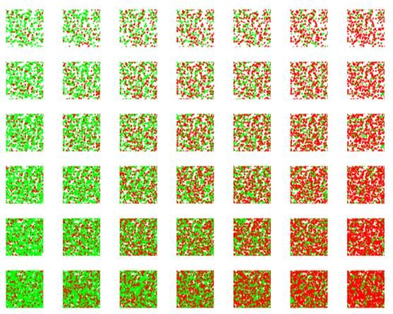
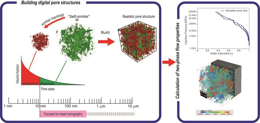
Research Report 2021 Institute of Computational Physics

 3D Pore Microstructures and Computer Simulation: Effective Per-
 meabilities and Capillary Pressure during Drainage in Opalinus
 Clay
In the present work, model pore structures of Opalinus Clay were used to predict critical material
properties related to gas transport. This topic is important, for example, because rocks such as
Opalinus Clay are considered as potential host rocks for the disposal of radioactive waste.
Thereby, these transport properties are of interest in connection with the production of gas, for
example through corrosion of the waste containers, and its subsequent transport through the
rock material surrounding the radioactive waste. The produced gas can be transported from the
place of formation through the rock by various transport processes (e.g. diffusion, advection,
two-phase flow etc.). Here, the focus is on the so-called two-phase transport where the produced
gas displaces the water in the pores as a separate phase.

Contributors: L. Keller
Partner(s): Nagra, EURAD
Funding: Nagra, EURAD
Duration: 2020–2023

The 3D reconstruction of the pore space in Opalinus The constructed pore structure has the same pore
Clay is faced with the difficulty that high-resolution im- size spectrum as measured in the laboratory. Com-
aging methods reach their limits at the nanometer- puter simulations were used to predict capillary pres-
sized pores in this material. Until now it has not been sure curves during drainage, which also agree with
possible to image the whole pore space with pore laboratory data. It is predicted, that two-phase
sizes that span two orders of magnitude. Therefore, transport properties such as the evolution of effective
it has not been possible to predict the transport prop- permeability as well as capillary pressures during
erties of this material with the help computer simula- drainage depend both on transport directions, which
tions that require 3D pore structures as input. Follow- should be considered for Opalinus Clay when as-
ing the concept of self-similarity, a digital pore micro- sessing its suitability as host rock for nuclear waste.
structure was constructed from a real but incomplete This directional dependence is controlled on the pore
pore microstructure. scale by a geometric anisotropy in the pore space.

 Figure 1: Graphical abstract related to the project.

Zurich University of Applied Sciences 10 www.zhaw.ch
Research Report 2021 Institute of Computational Physics

 Model Based Optimization of MIEC SOFC Anodes
Costs and lifetime are currently the limiting factors for a broader use of solid oxide fuel cells
(SOFC) with natural gas for combined heat and power. Therefore, a systematic optimization of
materials and cell-concepts is needed to increase lifetime and efficiency. In our approach we
build on digital materials design (DMD), whereby methods for multi-physics simulation, 3D mi-
crostructure characterization (tomography data) and electrochemical impedance spectroscopy
(EIS) are combined. Based on the DMD approach, the relations between material properties, mi-
crostructure, cell design and performance are established on a quantitative level. This approach
helps to define design guidelines for optimized MIEC electrodes and accelerates the innovation
cycle for future SOFC devices.

Contributors: P. Marmet, L. Holzer, T. Hocker, J. Brader, J. Grolig, H. Bausinger, A. Mai
Partner(s): Hexis AG
Funding: SFOE
Duration: 2019–2022

For the next generation of solid oxide fuel cells well as the DC behaviour during the normal cell op-
(SOFC), the requirements of the market call for eration. Therewith, a basic understanding of the com-
higher efficiency, longer lifetime and lower system plex physico-chemical processes and an appropriate
costs. In order to meet these requirements we elabo- interpretation of the EIS-spectra is achieved.
rate on new anode concepts, which are based on A calibrated simulation model is then used to predict
mixed ionic and electronic conductors (MIEC) like the impact of design adjustments (e.g. material and
doped ceria and perovskite materials. However, com- microstructure variations) on the cell performance. A
plex physico-chemical processes are involved includ- key point thereby is to include the effects from micro-
ing transport of gas in the pores, transport of ions and structure appropriately in the model.
electrons in the ceria phase, fuel oxidation reaction
on the surface of ceria etc. Hence, there are numer-
ous conflicting requirements, which complicate the
development process. Therefore, sophisticated
methods including mathematical models as well as
experimental methods are needed for a systematic
optimization of the system.

 Fig. 2: Area specific resistance (ASR) of CGO-anodes for different
 microstructures as a function of the anode layer thickness L.

 Microstructure analysis based on FIB-tomography
Fig. 1: Deconvolution of the simulated anode EIS-spectra: ZSR = hy- enables to quantify morphological characteristics
drogen oxidation surface reaction impedance, Zchrg tpt = charge car- (tortuosity, porosity etc) and the associated transport
rier transport imped., Zgas = gas imped., Zanode,tot = total anode imped.
 properties. With the digital materials design (DMD)
In SOFC research, electrochemical impedance spec- approach, the effect of microstructure variation on the
troscopy (EIS) is an essential characterization tool, cell performance can be assessed. By establishing
which serves as a basis for materials optimization on the relation between material properties, microstruc-
the electrode, cell and stack levels. Multi-physics ture, cell-design and performance, guidelines for a
simulation models developed at ICP with AC and DC new anode materials design can be deduced. This
modes, enable the simulation of the EIS-spectra as allows for a faster and more systematic development
 of new SOFC electrodes.

Zurich University of Applied Sciences 11 www.zhaw.ch
Research Report 2021 Institute of Computational Physics Massive Simultaneous Cloud Computing (MSCC) for Data Driven Optimization of SOFC Electrodes Digital Materials Design (DMD) enables a systematic model-based development and optimization of material systems and microstructures. Applying DMD for the development of Solid Oxide Fuel Cell (SOFC) electrodes results in a very large parameter space, which is very time-consuming with conventional computing approaches. The concept of Massive Simultaneous Cloud Compu- ting (MSCC) allows the access of almost unlimited computational resources on demand. This drastic reduction of computation times enables to exploit the full potential of the DMD approach for the development of the next generation of SOFC electrodes. Contributors: L. Holzer, P. Marmet, T. Hocker, G. Boiger, J. M. Brader, J. G. Grolig, H. Bausinger, A. Mai, M. Fingerle Partner(s): Hexis AG, Math2Market GmbH, Kaleidosim Technologies AG Funding: SFOE Duration: 2019–2022 Digital Materials Design (DMD) is a modern approach An example of a relatively small parameter study is for model-based materials optimization. In our DMD shown in Fig. 2, where the composition and porosity approach for optimization of SOFC electrodes, we of an LST/CGO anode is varied. combine stochastic microstructure modelling (i.e. simulating the effect of fabrication parameters on 3D morphologies), virtual testing of 3D microstructures and a multiphysics electrode model. This approach is capable to cover a very large parameter space, which Porosity → then provides a good basis for data driven micro- structure optimization. a) b) Composition → Figure 2: Example of a small parameter study for different porosities and compositions of an LST/CGO anode. Combined 3D analyses and numerical simulations Figure 1: a) Virtual LST/CGO structure of an SOFC anode with com- are used to characterize the virtual microstructures. puted potential drop, b) comparison of computation time with classi- cal and MSCC approach. Subsequently, the resulting effective properties are used as input for an electrode model, which provides However, very long computing times usually put the corresponding electrode performances in Fig. 3. strong limitations for extensive parameter sweeps. The statistical analysis of these results leads to new New concepts for Massive Simultaneous Cloud Com- design guidelines for electrodes with improved prop- puting (MSCC) were recently developed in a collabo- erties. ration of ZHAW, Kaleidosim AG and Math2Market, which gives access to almost unlimited computa- tional resources. Thousands of microstructures can be calculated in parallel. For a parameter study with e.g. 103–104 3D-scenarios as visualized in Fig. 1 b), the computing time for stochastic simulations and as- sociated virtual testing typically takes more than 1 year with a classical approach on a local server. In contrast, with MSCC the computing time is almost in- dependent from the number of parameter combina- tions and therefore it reduces to only 1–2 days. Figure 3: Resulting area specific anode resistance as a function of porosity and composition of an LST/CGO anode. Zurich University of Applied Sciences 12 www.zhaw.ch
Research Report 2021 Institute of Computational Physics

 Model-Based Development of Ceramic Filters for Masks, Air Purifi-
 ers and Air Conditioning Systems
The Covid-19 pandemic showed the importance of appropriate filters to prevent infections and
the need of more efficient and sustainable filter solutions. Ceramic filters have some significant
advantages regarding their sterilizability and environmental compatibility. Therefore, ceramic
filters are developed by an interdisciplinary team from ZHAW with a model-based approach.
Thereby, the manufactured multiscale ceramic filter structure is virtually reconstructed. By sim-
ulating the pressure loss and filter efficiency of many virtual filter designs, design guidelines for
an appropriate fabrication of the ceramic filters can be established.

Contributors: P. Marmet, L. Holzer, R. Kontic, M. Gorbar, D. Penner
Partner(s): Institute of Materials and Process Engineering (IMPE)
Funding: ZHAW
Duration: 2020–2021

In a project funded internally by the School of Engi-
neering at the ZHAW Zurich University of Applied Sci- b) d)
ences, a team of researchers is investigating the ad-
 a)
vantages of custom-made ceramic filters for aerosol c)
filtration and virus removal. Ceramic filters have
some significant advantages over standard filters,
which are made from polymer fibre fleeces. The mi-
crostructure and geometry of the ceramic pore chan-
nels can be adjusted over a wide range as desired.
Ceramics can be easily sterilised by simple heating,
making multiple use and internal regeneration of a fil-
ter possible. Ceramics are uncritical in terms of envi-
ronmental impact and recycling, while the massive
use and uncontrolled waste of polymer microfibres Figure 1: Microscopy image of the ceramic multiscale structure of
 the mesoscale a) and microscale b). Virtual reconstruction of the
represents a significant source of microplastics. mesoscale c) and microscale of the multiscale filter structure using
A team composed from researcher from the Institute GeoDict.

of Materials and Process Engineering (IMPE) and porous media calibrated by
 the microscale simulation
from the Institute of Computational Physics (ICP) is a) b)
using state-of-the-art modelling tools to create virtual
models of the porous ceramics produced in the labor-
atory and to investigate the pressure loss, permeabil-
ity and filtration performance of the materials. Based
on microscopy imaging (Fig. 1 a, b) the microstruc-
ture is virtually reconstructed using GeoDict software.
Thereby, the mesoscale and the microscale struc-
tures are captured in two different geometrical mod-
els (Fig. 1 b, c). In a first step, the permeability and
the filter efficiency statistics of the microscale are de-
 Figure 2: a) Simulation of the pressure drop in order to determine the
termined. Flow- and filtration simulations (Fig. 2 a, b) permeability and b) filtration simulation to determine the filter effi-
are then performed on the mesoscale, where the mi- ciency using GeoDict. The microscale of the structure is respected
 by calibrating its permeability and filter efficiency statistics in the po-
crostructure is modelled as a porous media, cali- rous media of the mesoscale structure.
brated by the permeability and filter efficiency statis-
tics of the microscale simulation. Therewith, the per- Once the model has been validated, laws can be de-
meability and the filter efficiency statistic can be de- rived from hundreds of virtually created structures,
termined for the complex multiscale structure. The re- which in turn serve ceramic researchers as a design
sults can then be compared with real measurements basis for their development. This reduces the number
on individual ceramic samples. of laboratory tests required to develop optimised filter
 materials that already take into account the standard
 requirements for the filter materials as a set frame-
 work.

Zurich University of Applied Sciences 13 www.zhaw.ch
Research Report 2021 Institute of Computational Physics

 Efficient Thermal Model for the Precise Prediction of Welding
 Times for Infrared Welded Plastic Pipes
Infrared welding is an established method for the welding of plastic pipes, characterised by a
high purity of the weld seam. In this process, the end faces of the pipes are heated by an infrared
heater until a fusion front of a few mm thickness is formed. The tubes are then pressed together
and cooled until the weld seam is solidified. To reduce the welding time to a minimum, an effi-
cient thermal model was developed that precisely predicts the temperature curve in the weld
seam during the entire welding process and thus provides the optimum time for unclamping the
welded pipes.

Contributors: T. Hocker, D. Kempf
Partner(s): ZHAW-IMPE Teams C. Brändli and D. Penner, Georg Fischer Piping Systems
Financing: Innosuisse
Duration: 2018–2021

Models for the thermal simulation of the infrared Figure 3 shows the savings potential for the welding
welding process of plastic pipes are usually imple- time resulting from the precise prediction of the opti-
mented in FE or CFD tools. In these models, the pipe mal unclamping time of the welded pipes. The model
ends to be welded, the IR heater and the surrounding has now been implemented in Java and is to be used
air are discretized in 105–106 elements. For each time in the future in the GF welding machines.
step, the energy balance must be solved in each ele-
ment of both the pipe and the heater, and the mass
and momentum balances must also be solved within
the ambient air. The resulting simulation times in the
range of several hours are too long to be used in the
control software of the IR welding machine. For this
purpose, a model is needed that simulates the T-pro-
gression in the weld seam during the entire welding
process in only a few seconds.
Therefore, in cooperation with Georg Fischer Piping
Systems, a new model was developed that divides Fig. 2: Validation of the weld temperatures predicted by the model
 via welding tests with T-sensors placed in the weld seam.
the pipe ends to be welded into only five segments,
see Figure 1.

Fig. 1: The model is based on the discretisation of the pipe ends into
 Fig. 3: Shortening of the welding time of plastic pipes when using the
only five segments.
 newly developed model, which simulates the behaviour of the weld
 seam temperatures and thus predicts the optimum unclamping time
In each of these five segments, an energy balance is of the welded pipes.
solved which takes into account all heat flows by con-
duction, natural convection, forced convection and
thermal radiation. The phase transitions during melt-
ing and subsequent recrystallisation of the tube ends
are represented by a model that is calibrated using
DSC data.
Figure 2 shows the typical behaviour of the weld tem-
peratures simulated in the model and the corre-
sponding measurement data determined in real weld-
ing tests. Details such as the T-plateau during recrys-
tallisation are also correctly predicted.

Zurich University of Applied Sciences 14 www.zhaw.ch
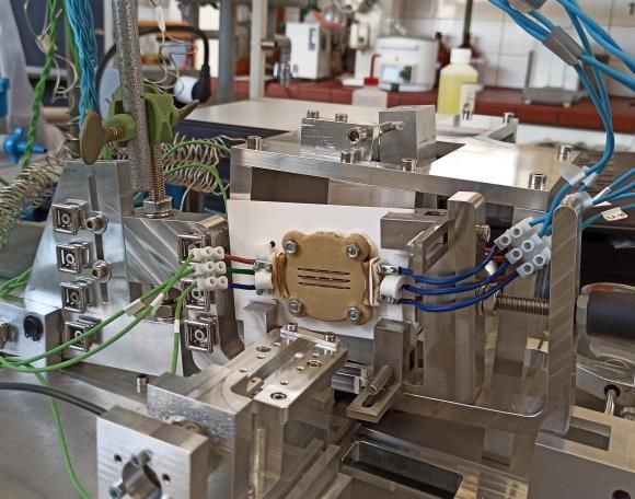
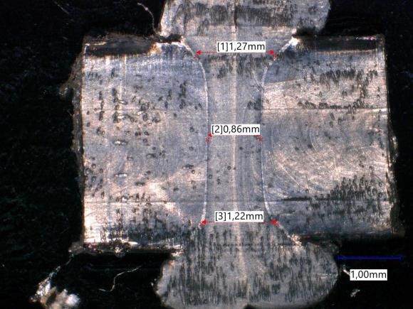
Research Report 2021 Institute of Computational Physics

 Development of a New Type of IR Heating Concept for Contactless
 Welding of Plastic Pipes
If the purity of the weld seams is central when joining plastic pipes to form entire piping systems,
infrared welding technology is often used. Here, the pipes are first heated at their end faces by
an infrared heater using radiant heat until the plastic melts, and then pressed together. The plas-
tic melts combine, and cooling produces a material bond. The introduction of a new type of IR
heating concept is intended to shorten the heating process and thus the entire welding process.

Contributors: N. Jenal, M. Gorbar, S. Spirig, T. Hocker, C. Brändli
Partner(s): ZHAW-IMPE Teams C. Brändli and D. Penner, Georg Fischer Piping Systems
Funding: Innosuisse
Duration: 2018–2021

The previous heating system consists of a solid plate
with a high thermal mass and is characterized by a
homogeneous surface temperature. However, this
heating technology, which has proven itself over dec-
ades, has two decisive disadvantages: the heating is
very sluggish, and the large-area heat emission can
lead to uneven melting of the tube ends. Therefore, a Melting
new IR heating concept was developed in coopera- front
tion with GF, with which the heating can be operated
dynamically, zone-based and adaptively. The new
heater consists of several fine heating wires on a ce-
ramic support, which enable a targeted and econom-
ical heating process. This concept was developed us-
ing thermal-fluid computer models and verified with Fig. 2: Microtome section of a weld seam under a light microscope.
the aid of a designated welding test rig, see Fig. 1.
 However, the step from a small prototype heater to a
 large prototype heater close to the application repre-
 sents another hurdle. To get closer to this goal, a
 combination of theoretical and experimental methods
 is used. For example, undesirable, inhomogeneous
 temperature distributions on the heating wire surface
 due to thermally conductive contact points between
 the heating wire and the support are optimized via
 CFD models, see Fig. 3.

 Heater

 Sample holder

Fig. 1: Test bench for welding plastic samples.

With the new IR heater, it was shown that the used
cuboid plastic specimens could be optimally welded.
Their melt fronts had a very uniform shape along the
wall thickness, see Fig. 2.
 Fig. 3: Temperature distribution on the heating wire surface.

Zurich University of Applied Sciences 15 www.zhaw.ch
You can also read