Robotix-Academy Conference for Industrial Robotics (RACIR) 2020
←
→
Page content transcription
If your browser does not render page correctly, please read the page content below
Robotix-Academy
                                                          Robotix-Academy
                                                          Robotix-Academy Conference
                                                                             Conference
                                                                             Conferenceforfor
                                                                                          for
                                                        Industrial
                                                          Industrial
                                                          Industrial
                                                                   Robotics
                                                                     Robotics
                                                                     Robotics
                                                                            (RACIR)
                                                                              (RACIR)
                                                                              (RACIR)
                                                                                    2020
                                                                                      2020
                                                                                      2020

                      [B]                                                                                         [ B]                [B[]B]

                            [L]
                                              Rainer
                                                  Rainer
                                                  Rainer
                                                     Müller,
                                                         Müller,
                                                         Müller,
                                                             Peter
                                                                 Peter
                                                                 Peter
                                                                   Plapper,
                                                                       Plapper,
                                                                       Plapper,
                                                                            Olivier
                                                                                Olivier
                                                                                 Olivier
                                                                                    Brüls,
                                                                                         Brüls,
                                                                                         Brüls,
                                                                                           Wolfgang
                                                                                                Wolfgang
                                                                                                Wolfgang
                                                                                                     Gerke,
                                                                                                         Gerke,
                                                                                                         Gerke,          [ L]                  [L][L]

                                              Gabriel
                                                 Gabriel
                                                 Gabriel
                                                      Abba,
                                                         Abba,
                                                         Abba,
                                                            Bassem
                                                               Bassem
                                                                Bassem
                                                                   Hichri,
                                                                       Hichri,
                                                                       Hichri,
                                                                           Ali Kanso
                                                                                Ali
                                                                                Ali Kanso
                                                                                    Kanso
                                                                                      (Hrsg.)
                                                                                          (Hrsg.)
                                                                                           (Hrsg.)
                                        [D]                                                                                                    [D]               [D[]D]

                                  [F]                                                                                           [F]                     [F][F]

www.robotix.academy                           www.robotix.academy
                                               www.robotix.academy
                                               www.robotix.academy
Berichte aus der Robotik

               Rainer Müller, Peter Plapper,
      Olivier Brüls, Wolfgang Gerke, Gabriel Abba,
            Bassem Hichri, Ali Kanso (Hrsg.)

Robotix-Academy Conference for Industrial Robotics
                 (RACIR) 2020

                     Shaker Verlag
                      Düren 2020
Bibliographic information published by the Deutsche Nationalbibliothek
The Deutsche Nationalbibliothek lists this publication in the Deutsche
Nationalbibliografie; detailed bibliographic data are available in the Internet at
http://dnb.d-nb.de.

Copyright Shaker Verlag 2020
All rights reserved. No part of this publication may be reproduced, stored in a
retrieval system, or transmitted, in any form or by any means, electronic,
mechanical, photocopying, recording or otherwise, without the prior permission
of the publishers.

Printed in Germany.

ISBN 978-3-8440-7606-6
ISSN 1434-8098

Shaker Verlag GmbH • Am Langen Graben 15a • 52353 Düren
Phone: 0049/2421/99011-0 • Telefax: 0049/2421/99011-9
Internet: www.shaker.de • e-mail: info@shaker.de
Robotix-Academy Conference for Industrial
Robotics (RACIR) 2020
Preface:
                                            The topics concerned by RACIR are: ro-
Robotix-Academy Conference for In-          bot design, robot kinematics/dynam-
dustrial Robotics (RACIR) is held at        ics/control, system integration, sen-
ZeMA, Germany, during July 16, 2020         sor/actuator networks, distributed and
as a web conference due to the effects of   cloud robotics, bioinspired systems,
the Covid-19 crisis.                        service robots, robotics in automation,
The venue for RACIR 2020 is the ZeMA        biomedical applications, autonomous
- Center for Mechatronics and Automa       vehicles (land, sea, and air), robot per-
tion. Founded in 2009, ZeMA sees            ception, manipulation with multifinger
itself as a development partner with        hands, micro/nano systems, sensor in-
the goal of industrialization and           formation, robot vision, multimodal in-
technology transfer of research and         terfaceand human-robot interaction.
development results.
Working closely with institutes and         Acknowledgements:
chairs at Saarland University (UdS)         The Robotix-Academy partners and the
and the University of Applied Sci-          participating students are acknowledged
ences (htw saar), ZeMA passes on its        for their contributions and participation to
research results to companies through       the conference.
an actively pursued technology trans-
fer. In addition, ZeMA plays an active      The organisation committee and in-
role in academic training.                  volved persons are also acknowledged
                                            for their help and support.
Content

 1   Soft finger modeling using a nonsmooth contact approach                    1
     Olivier Devigne, Alejandro Cosimo and Olivier Brüls

 2   Modified Feedback Linearization for Underactuated Cable Robot              7
     Control: Case studies
     Atal Anil Kumar, Jean-François Antoine, Vianney Papot, Patrick Zattarin
     and Prof. Dr. Gabriel Abba

 3   A synchronized-HRC pick and place application using an intelligent        14
     vision system
     Prof. Dr.-Ing. Rainer Müller, Nishant Ketan Gajjar, Ahmad El Masri and
     Khansa Rekik

 4   Hybrid Workstations: A Simultaneous Planning Method for                   19
     Economic-oriented Selection between Industrial and Collaborative
     Robots
     Christopher Schneider, Thomas Suchanek, Martina Hutter-Mironovova,
     Francisco Hernandez, Mohamad Bdiwi and Matthias Putz

 5   Practically Oriented Investigation of Sensitive Robots Regarding the      27
     Execution of Force Controlled Applications
     Prof. Dr.-Ing. Rainer Müller, Ali Kanso and Marco Schneider

 6   External communication of the robot ABB YuMi via virtual machine          35
     with analysis of hybrid position-force control
     Wang Yiguo, Meryem Taghbalout, Jean-François Antoine and Gabriel
     Abba

 7   Mobile Robot Lifting Mechanism Design for Manipulation and                41
     transportation task
     Bassem Hichri and Peter Plapper

 8   Mobile Robots Target Reaching and Virtual Structure Navigation            49
     Based on Limit-Cycle Method
     Bassem Hichri and Peter Plapper

 9   Unconventional path planning for a serial kinematics robot with           55
     Reinforcement Learning using the example of the wire loop game
     Prof. Dr.-Ing. Rainer Müller, Ali Kanso and Stefan Marx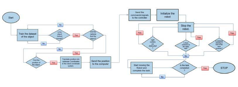
Robotix-Academy Conference for Industrial Robotics RACIR 2020 at ZeMA during July 16th, 2020

     Soft finger modeling using a nonsmooth contact
                       approach
                       Olivier Devigne                                                        Alejandro Cosimo
  Department of Aerospace and Mechanical Engineering                  Department of Aerospace and Mechanical Engineering
                   University of Liège                                                  University of Liège
                    Liège, Belgium                                                        Liège, Belgium
                  o.devigne@uliege.be                             Centro de Investigación de Métodos Computacionales (CIMEC)
                                                                           Universidad Nacional del Litoral - CONICET
                                                                                        Santa Fe, Argentina
                                                                                         acosimo@uliege.be

                      Olivier Brüls
Department of Aerospace and Mechanical Engineering
                 University of Liège
                  Liège, Belgium
                 o.bruls@uliege.be

   Abstract—In the frame of accurate grasping and safer human-            humans. Soft robots are also particularly relevant in the frame
robot interactions, soft robots are an emerging and promising             of surgical robotics [4]. Moreover, they do not depend on
technology. Due to the fact that they do not rely on joints to            classical manufacturing techniques and can be easily replaced
produce a motion, but on deformation, they have a theoretically
infinite number of degrees of freedom. This particularity calls            at low financial costs, for instance, using 3D printing.
for advanced numerical models to analyze them. Although some                 As previously mentioned, soft robots do not rely on joints
modeling tools have already been developed by other research              to move, as it is the case for classical industrial robots,
teams, many open questions remain and should be addressed                 but on a deformation of their own structure. Three main
to accurately represent this kind of robots. Our work relies              actuation types can be distinguished. The first one is based
on the development of a research code for analyzing flexible
multibody systems. This code is based on a Lie group formalism            on a local deformation induced by a linear actuator such as
which is coupled with state-of-the-art nonsmooth algorithms for           a pneumatic cylinder. The second one relies on pressure or
solving contact interactions. This numerical formulation opens            vacuum actuation by inflating or deflating a chamber inside the
the possibility to later consider more advanced models for                structure. This actuation type produces a more global action
describing the flexibility characterizing these problems, such as,         on the whole robot. The third one is the technique which is
for example, geometrically exact beam and shell elements. In
this paper, a frictionless soft finger model able to interact with         investigated in this paper, called cable actuation. In this case,
a sphere is introduced as a first prototype intended to test and           a cable is attached to different points of the compliant robot
present our code capabilities.                                            and is pulled so that the structure is locally and/or globally
   Index Terms—soft robot, soft gripper, geometrically exact,             deformed.
nonsmooth, contact                                                           Based on the fact that soft robots rely on the deformation
                                                                          of their structure to achieve a task, theoretically speaking,
                       I. I NTRODUCTION                                   they can be characterized by an infinite number of degrees
   A new generation of robots has recently made its appearance            of freedom. This complexity calls for advanced numerical
in the robotics community. Made of so-called “soft” materials,            models for simulation, virtual prototyping or for control design
such as plastic or silicone, these robots, in contrast to classical       purpose. Many times, the simulation should be executed in
“rigid” robots, achieve their tasks by following a trajectory             real-time [5], which can motivate the drastic simplification of
that is accomplished through a deformation of their struc-                the physics of the problem, as it is the case in [6], where
ture. These soft robots can be used in various applications               only a sticking friction model is implemented for the gripper.
such as those requiring a safer human-robot interaction or                The error on the controlled point between the simulation
those involving the manipulation of fragile objects [1]–[3].              and the physical demonstrator can be in the order of several
Indeed, the soft nature of the material used to build them                millimeters. This value should be put in light with the accuracy
allows for extended grasping capabilities which is achieved               of an industrial robot which achieves a precision of some
by modulating the shape of the gripper and the contact force              tenths of a millimeter.
exerted on the object. This also ensures a reduction in the                  A myriad of applications are targeted by soft robots. This
severity of impacts in environments involving interactions with           paper specifically focuses on finger-like grippers. Although

                                                                      1
Robotix-Academy Conference for Industrial Robotics RACIR 2020 at ZeMA during July 16th, 2020

conceptually simple, these “soft fingers” reveal several in-              a node and the matrix R, which belongs to the rotation group
teresting numerical challenges. Indeed, contact and friction             SO(3), is used to represent its orientation, both measured with
between the gripper and the object (or with the gripper itself)          respect to the chosen inertial frame. An element from SE(3)
should be considered. Moreover, the inherent flexibility of the           can be assimilated to a local frame attached to the body of
gripper must be taken into account. Finally, control parameters          the object under analysis. In this context, the translational
can be tuned through experimental identification.                         velocity is represented by u = RT ẋ which is interpreted
   In order to deal with these challenges, a plugin in the open-         as the velocity of the reference point x with respect to the
source software SOFA is developed in [7]. However, they have             inertial frame but resolved on the body-attached frame. The
a constraint on the number of vertices that can be used to               rotational velocity is represented by the vector Ω ∈ R3 in
approximate the 3D geometry in order to satisfy the real-time            the body-attached frame. By arranging both velocities in the
requirement. They are planning to adopt reduced order models             vector v T = [uT Ω T ], the relation between the time derivative
in order to remove this constraint. Nevertheless, although these         of the configuration q̇ and v is given by a (nonlinear) kinematic
models perform well for preliminary analyses, they cannot be             compatibility condition of the form q̇ = h(q, v).
used for detailed analyses. In addition, their plugin is not open-          In any multibody system, it is of great importance to be
source. In the context of the computer animation community, a            able to model kinematic joints which describe the restricted
methodology to solve contact problems based on a nonsmooth               relative motion between two bodies. They are stated as equality
formalism is tested on the simulation of a soft robot in [8].            conditions and, therefore, are classified as bilateral constraints.
Despite some nice features, bilateral constraints are replaced           In order to model contact, we can assume that it develops as
by compliant models, and the contacts are described using a              an impulsive process in which the velocity changes instanta-
kind of node-to-surface technology that is known to have many            neously in a discontinuous manner at an impact event. This
drawbacks for the collision of flexible to flexible bodies [9].            nonsmooth (or impulsive) description of contact processes
This motivates the development of a more general research                introduces non-equality conditions or unilateral constraints to
code, able to deal with the numerical challenges mentioned               the problem. The contact interaction between two bodies A
above.                                                                   and B at the points xA and xB from bodies A and B,
   The aim of this paper is double. Firstly, we introduce a              respectively, is described by the gap g = nT (xB − xA ),
robust modeling of highly flexible systems using a geomet-                where n is the outward unit normal from the surface of body
rically exact 3D approach [10]. The representation is based              A. At position level, whenever there is contact, the gap is
on the nonlinear finite element method where a local frame                zero and the contact reaction force Fc takes a positive value.
is defined at each node, and is treated as an element of the              On the contrary, when there is no contact, i.e. g > 0, the
special Euclidean group SE(3). The ability to express the                contact force vanishes. This complementarity relation is stated
equations of motion in SE(3) yields interesting properties,              by the Signorini contact law as 0 ≤ g ⊥ Fc ≥ 0, which is
noticeably for flexible elements, because their deformation               an abbreviation of the three conditions g ≥ 0, Fc ≥ 0 and
measure is expressed in a local frame, giving an invariance              gFc = 0. At velocity level, a similar relation holds, however,
property to the equations under a superimposed Euclidean                 an impact law must be provided in order to relate the pre-
transformation [11], [12]. Secondly, this representation is              impact and post-impact velocities. It is important to note that
coupled with a more physical contact model relying on a                  the velocity field will be not continuous. Therefore, the usual
sophisticated nonsmooth solver based on the generalized-α                equations of motions expressed in terms of partial differential
integration scheme [13]. As an illustration of this algorithm            equations are not valid anymore. In order to solve this issue,
capabilities, a frictionless soft finger gripper is presented.            the equations of motion are written in terms of differential
   The paper is organized as follows. In Section II, the non-            measures. The interested reader can find out more about this
smooth equations of motion and the time integration method               in [15], [16].
are briefly presented. In Section III, the soft finger is first                Under this setting, the equations of motion for a frictionless
described as a physical object before introducing the modeling           multibody system with unilateral and bilateral constraints
assumptions. Results are shown in Section IV. Finally, Section           expressed at velocity level are written in the following form:
V gives the conclusions and future work perspectives.
   II. E QUATIONS OF MOTION AND TIME INTEGRATION                                                     q̇ +     =   h(q, v + )          (1a)
                                                                                       M (q) dv − gqT di      =   f (q, v, t) dt      (1b)
   In order to describe the motion of flexible multibody
dynamic systems, such as soft robots, the nonlinear finite                                        −gqU v +     =   0                   (1c)
element method is adopted [10]. In this setting, the elements               if g j (q) ≤ 0 then 0 ≤ gqj v +   +   ej gqj v − ⊥ dij ≥ 0,(1d)
comprising a mechanical system are represented by a set of
                                                                                                                        ∀j ∈ U
nodal variables q of nodal position and orientation. It must be
emphasized that when dealing with large rotations, q does not
belong to a linear vector space but to a Lie group [14]. In the          where
current work, we adopt the special Euclidean group SE(3),                  •   t is the time, and dt is the corresponding standard
where the vector x ∈ R3 is used to represent the position of                   Lebesgue measure.

                                                                     2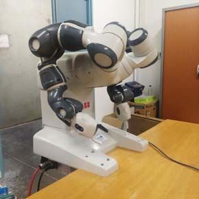
Robotix-Academy Conference for Industrial Robotics RACIR 2020 at ZeMA during July 16th, 2020

  •   q(t) is the set of nodal variables, which are absolutely              method, whereas the nonsmooth part is integrated using a first-
      continuous in time.                                                   order scheme. One distinctive feature of this method is that,
  •   U denotes the set of indices of the unilateral constraints,           through the adoption of a similar procedure proposed in [22],
      U is its complementarity set, i.e., the set of bilateral              the unilateral and bilateral constraints are simultaneously sat-
      constraints, C = U ∪ U is the full set of constraints.                isfied both at position and velocity levels in order to avoid drift
  •   g is the combined set of bilateral and unilateral con-                phenomena. The resulting scheme is characterized by a set of
      straints, and gq (q) is the corresponding matrix of con-              three coupled sub-problems: one for the smooth prediction of
      straint gradients.                                                    the motion and two others for the corrections at position and
  •   q̇ + (t) = limτ →t,τ >t q̇(τ ) and v + (t) = limτ →t,τ >t v(τ )       at velocity levels. Quite recently, a decoupled version of the
      are the right limits of the velocity, which are functions of          NSGA method was presented in [13]. This specific version is
      bounded variations. Similarly, v − (t) = limτ →t,τ  0, the relative post-impact velocity gqj v + has to             that need to be solved at every time step. This feature improves
      change instantaneously by an impulsive process, modeled               considerably the robustness of the integrator for problems
      by enforcing the Newton impact law gqj v + = −ej gqj v − ,            involving nonlinear bilateral constraints and flexible elements.
      where ej is the coefficient of restitution at the contact              From a practical point of view, the NSGA method involves
      point j. In the event in which the contact point j is                 the following steps, each of them performed in a decoupled
      superfluous (see e.g. [17]), dij = 0 and gqj v + can take              manner at each time step of the simulation:
      any value satisfying gqj v + ≥ −ej gqj v − . One can observe            1) Solve for the smooth prediction of the motion: only
      that in Eq. (1d), it is implicitly assumed that in the case of             bilateral constraints are involved.
      g j (q) > 0, then dij = 0. In what follows, for simplicity,             2) Collision detection: detect which pair of bodies could be
      v(t) and q̇(t) will be used to denote v + (t) and q̇ + (t),                in contact and create the corresponding contact elements.
      respectively.                                                           3) Solve for the position correction: both bilateral and
  •   f (q, v, t) = f ext (t)−f cin (q, v)−f damp (q, v)−f int (q)               unilateral constraints are involved.
      collects the external, complementary inertia, damping and               4) Solve for the velocity jump: both bilateral and unilateral
      internal forces.                                                           constraints are involved.
  •   M (q) is the mass matrix which may, in general, depend
      on the coordinates.                                                      Remark: in order to perform the collision detection phase
  •   dv is the differential measure associated with the velocity           the corresponding capabilities provided by the Bullet Physics
      v, assumed to be of bounded variations.                               library [23] are used. The rest of the algorithmic steps are
  •   di is the impulse measure of the unilateral contact                   implemented within our in-house code.
      reaction and the bilateral constraint forces.
                                                                                         III. S OFT FINGER DEMONSTRATOR
   The numerical integration of the equations of motion must
be performed with special care, not only because of the                        In this Section, a soft finger-like gripper is presented. Its
nonsmooth nature of the equations but also because of the                   aim is to provide a conceptually simple but yet representative
presence of flexible components. In this context, time in-                   model. Indeed, nonsmooth behaviors are dominating during
tegration schemes can be classified into event-driven and                    the grasping operation. The physical robot that our numerical
time-stepping schemes. The former adapt their time step to                  model wishes to represent is first introduced. Afterwards, the
the impact events, whilst the others do not. One inherent                   modeling assumptions that have been made are explained.
disadvantage of event-driven methods is that they do not
perform well for systems with accumulation points or a large                A. Physical demonstrator description
number of contacts. Therefore, this work concentrates on time-
stepping methods. One of the most widespread method of this                    In order to highlight nonsmooth behaviors, a soft finger
kind is the Moreau–Jean scheme [18]–[20]. Despite its good                  gripper displaying a motion history characterized by many
performance, it is dissipative for problems involving flexibility            impact events is modeled. A pressure-actuated version of
and suffers from drift issues at position level. In order to avoid          this example is well-known in the soft robotics community
these issues, we adopt the nonsmooth generalized-α (NSGA)                   under the name PneuNet [24]. However, the finger can also
scheme. It was introduced in [21] for the solution of contact               be cable-actuated, as presented in [7]. This last technology
and impact problems in multibody dynamics. This algorithm                   is investigated in this paper. An illustration of the system is
artificially splits the motion into smooth and nonsmooth (im-                presented in Fig. 1. When the cable is pulled, the finger will
pulsive) components. In order to correctly capture the vibration            bend thanks to the low rigidity of the interphalangeal spaces.
effects of problems with flexible components, the smooth part                In the case of a complete gripper, three fingers are usually
is integrated using the second-order accurate generalized-α                 used to grasp objects.

                                                                        3
Robotix-Academy Conference for Industrial Robotics RACIR 2020 at ZeMA during July 16th, 2020
Phalanges potential energy of the cable writes
σ = Eε (3)
x6 x5 x4 x3 x2 x1
1 l
V= EAε2 ds (4)
2 0
Interphalangeal spaces 1 EA 2
= Δl (5)
2 l
Fig. 1: Cable actuation of a soft finger. The different passing
Δl
points of the cable through the structure are represented. with the unstretched length l, the strain ε = l , which is con-
sidered constant over the whole cable, the Young’s modulus
E and the cross-sectional area A. Under these assumptions,
the cable behaves as a spring of stiffness EA l . Because of the
Phalanges assumption of a linear stress-strain constitutive law in Eq. 3,
the model is not able to represent slackness. Indeed, a real
cable can only withstand traction forces. Therefore, the current
Cable
Hinge
version of this model is only valid in traction.
Finally, no friction is considered in this preliminary model.
The grasping operation represented by the model is thus
incomplete, in the sense that the gripper can get in contact
with the object but the contact forces are only represented in
the normal direction.
IV. N UMERICAL RESULTS
(a) Initial configuration of the sphere and finger (t = 0 s).
The dynamics of a finger-like gripper comprised of one
0.25cm finger made of two phalanges is studied next. The initial
1cm configuration of the problem can be observed in Fig. 2(a)
where it can be appreciated that the gripper will interact with
0.75cm a sphere that is free to move on a flat ground.
The aim behind this example consists in showing the capa-
bilities that we have for the modeling of this kind of problems.
2cm
The parameters of the studied problem are specified as follows.
(b) Geometry of the finger phalanges. The finger is actuated by a flexible cable with a stiffness
Fig. 2: Initial configuration of the finger model and geometry constant of 105 N/cm which links the two phalanges and the
of its phalanges. actuation mechanism. This mechanism exerts a force which
increases from (0, 0, 0) to (0, −120, 0) N in 2 seconds and it
remains constant at that value for the rest of the simulation.
B. Numerical model assumptions The two phalanges are joined by a hinge which, as previously
mentioned, also models an internal stiffness and damping,
In this first virtual prototype, the finger is modeled using the taking as parameters a stiffness constant of 10−2 N.cm/rad
following assumptions. Firstly, although the finger is made of and a damping coefficient of 1 N.s/rad. One of the phalanges
a soft material, it can be observed, as it is the case for a is linked to the ground through a hinge which is characterized
real human finger, that the deformation is highly localized by a stiffness constant of 1 N.cm/rad and a damping coefficient
in the interphalangeal space. Thus, as a first approximation, of 1 N.s/rad. The acceleration of gravity is neglected. The level
we consider the finger as made of rigid bodies interconnected of the ground is set at 1 cm in the y-direction. At the initial
by hinge joints, allowing it to bend. The implication of this time step t = 0, the center of mass of the sphere of radius
assumption is that the deformation of the phalange is neglected r = 0.5 cm is located at (0, 1.5, 1.5) cm, and the center of
by the model. The torque resulting from the local deformation mass of the two phalanges are located at (0, 2.5, 0) cm and
of the interphalangeal space is modeled by a torsional spring (0, 5.5, 0) cm with respect to the inertial frame of reference.
element coupled to the hinge joint. The geometry of the phalanges can be observed in Fig. 2(b).
Secondly, the cable needs to be modeled. Considering that The shape and dimensions have been chosen to represent the
the cable is extensible, the length variation, according to the same type of finger as in [7]. For the impact law, the restitution
notation in Fig. 1, can be expressed as coefficient is taken as 0.
It should be emphasized, as mentioned above, that we are
Δl = ||x2 − x1 || + ||x3 − x2 || + · · · + ||xn − xn−1 || − l (2) solving the frictionless problem. Certainly, friction is a really
important phenomenon to take into account in this kind of
Assuming a linear elastic behavior in the axial direction, the applications. However, one of the aims of this work is to show
4Robotix-Academy Conference for Industrial Robotics RACIR 2020 at ZeMA during July 16th, 2020
Upper phalange vy
3
Ground phalange vy
Sphere vz
2
Velocity [cm/s]
1
0
(a) t = 2.0 s −1
0 1 2 3 4 5 6
Time [s]
(a) Velocity of the phalanges of the finger and the sphere.
Upper phalange vy
0.4 Ground phalange vy
Sphere vz
Velocity [cm/s]
0.2
0.0
(b) t = 2.75 s
−0.2
−0.4
4.75 5.00 5.25 5.50 5.75 6.00
Time [s]
(b) Zoom of the velocity of the phalanges of the finger and the sphere.
Fig. 4: Results of the soft finger simulation: velocities of the
phalanges and the sphere.
Fig. 4(a), the velocity of the phalanges of the finger and
(c) t = 3.14 s
the sphere are shown. It is important to observe that the
Fig. 3: Results for the soft finger simulation: render of the adopted nonsmooth formulation is able to correctly capture
finger interacting with the sphere at different time steps. all the jumps in the velocity field (i.e. all the contacts). The
first jump actually represents the contact between the two
phalanges. In this case, a relatively large time increment of
the current state of our developments, not only in terms of 0.01 s was used for the simulation, and, actually, higher values
physically-sounded numerical formulations, but also in terms could even be used. Consequently, the nonsmooth nature of
of source code development to solve applications of interest the adopted numerical scheme is efficient from the point of
for the robotics industry. view of the size of the time increments. In addition, Fig. 4(b)
In Figs. 3, snapshots of the time evolution of the obtained shows that no numerical artifact is observed at the end of
solution can be observed. As it can be appreciated, in response the simulation. That is, the velocity is exactly zero when
to the actuation of the force transmitted through the cable, the the system is at rest, where other formulations could exhibit
gripper adapts its shape until it comes in contact with the oscillations of numerical nature. Moreover, it has been verified
sphere. At the end of the simulation, t = 6 s, the sphere that no penetration occurred, so that no drift phenomena are
is totally enclosed between the phalanges of the finger. In noticed.
5Robotix-Academy Conference for Industrial Robotics RACIR 2020 at ZeMA during July 16th, 2020
V. C ONCLUSIONS AND FUTURE WORK [14] O. Brüls, A. Cardona, and M. Arnold, “Lie group generalized-α time
integration of constrained flexible multibody systems,” Mechanism and
In this paper, a first prototype of a frictionless soft finger- Machine Theory, vol. 48, pp. 121–137, 2012.
like gripper was proposed. A Lie group formulation of the [15] B. Brogliato, Nonsmooth Mechanics. Springer International Publishing,
2016.
equations of motion is coupled with an efficient nonsmooth [16] R. I. Leine and N. van de Wouw, Eds., Stability and Convergence
time integration algorithm in order to account for contacts of Mechanical Systems with Unilateral Constraints. Springer Berlin
between the gripper and the object. As a first approximation, a Heidelberg, 2008.
[17] C. Glocker, An Introduction to Impacts. Vienna: Springer Vienna, 2006,
model consisting in two rigid bodies interconnected by a hinge pp. 45–101.
joint is used to represent the finger, whereas a spring element [18] M. Jean and J. J. Moreau, “Dynamics in the presence of unilateral
is chosen to model the cable. Our model is able to capture contacts and dry friction: A numerical approach,” in Unilateral Problems
in Structural Analysis — 2. Springer Vienna, 1987, pp. 151–196.
nonsmooth interactions with a rigid sphere, accurately catching [19] J. J. Moreau, “Unilateral contact and dry friction in finite freedom
the discontinuities in the velocity. However, the deformation dynamics,” in Nonsmooth Mechanics and Applications. Springer
of the phalanges is not modeled and slack cables cannot Vienna, 1988, pp. 1–82.
[20] M. Jean, “The non-smooth contact dynamics method,” Computer Meth-
be represented. Additionally, no friction is implemented, so ods in Applied Mechanics and Engineering, vol. 177, no. 3-4, pp. 235–
that the grasping operation is incomplete. In the future, we 257, 1999.
wish to experimentally identify parameters from a real soft [21] O. Brüls, V. Acary, and A. Cardona, “Simultaneous enforcement of
constraints at position and velocity levels in the nonsmooth generalized-
finger, implement a working friction model and use more α scheme,” Computer Methods in Applied Mechanics and Engineering,
sophisticated flexible elements such as beams or shells, taking vol. 281, pp. 131–161, 2014.
advantage of our geometrically exact formulation. [22] C. W. Gear, B. Leimkuhler, and G. K. Gupta, “Automatic integration of
Euler-Lagrange equations with constraints,” Journal of Computational
and Applied Mathematics, vol. 12-13, pp. 77–90, 1985.
ACKNOWLEDGMENT [23] E. Coumans et al., “Bullet physics library,” Open source: bullet-
physics.org, vol. 15, no. 49, p. 5, 2013.
This work is partly funded by the Robotix Academy project [24] F. Ilievski, A. D. Mazzeo, R. F. Shepherd, X. Chen, and G. M.
of the Greater Region. Whitesides, “Soft robotics for chemists,” Angewandte Chemie, vol. 123,
no. 8, pp. 1930–1935, 2011.
R EFERENCES
[1] H. Lipson, “Challenges and opportunities for design, simulation, and
fabrication of soft robots,” Soft Robotics, vol. 1, no. 1, pp. 21–27, 2014.
[2] Z. Wang and S. Hirai, “A 3D printed soft gripper integrated with curva-
ture sensor for studying soft grasping,” in 2016 IEEE/SICE International
Symposium on System Integration (SII). IEEE, 2016, pp. 629–633.
[3] Y. Wei, Y. Chen, T. Ren, Q. Chen, C. Yan, Y. Yang, and Y. Li, “A novel,
variable stiffness robotic gripper based on integrated soft actuating and
particle jamming,” Soft Robotics, vol. 3, no. 3, pp. 134–143, 2016.
[4] M. Cianchetti, T. Ranzani, G. Gerboni, T. Nanayakkara, K. Althoefer,
P. Dasgupta, and A. Menciassi, “Soft robotics technologies to address
shortcomings in today’s minimally invasive surgery: the stiff-flop ap-
proach,” Soft robotics, vol. 1, no. 2, pp. 122–131, 2014.
[5] E. Coevoet, A. Escande, and C. Duriez, “Optimization-based inverse
model of soft robots with contact handling,” IEEE Robotics and Au-
tomation Letters, vol. 2, no. 3, pp. 1413–1419, 2017.
[6] ——, “Soft robots locomotion and manipulation control using fem
simulation and quadratic programming,” in 2019 2nd IEEE International
Conference on Soft Robotics (RoboSoft). IEEE, 2019, pp. 739–745.
[7] E. Coevoet, T. Morales-Bieze, F. Largilliere, Z. Zhang, M. Thieffry,
M. Sanz-Lopez, B. Carrez, D. Marchal, O. Goury, J. Dequidt et al.,
“Software toolkit for modeling, simulation, and control of soft robots,”
Advanced Robotics, vol. 31, no. 22, pp. 1208–1224, 2017.
[8] M. Macklin, K. Erleben, M. Müller, N. Chentanez, S. Jeschke, and
V. Makoviychuk, “Non-smooth newton methods for deformable multi-
body dynamics,” ACM Transactions on Graphics (TOG), vol. 38, no. 5,
pp. 1–20, 2019.
[9] F. J. Cavalieri and A. Cardona, “An augmented Lagrangian technique
combined with a mortar algorithm for modelling mechanical contact
problems,” International Journal for Numerical Methods in Engineering,
vol. 93, no. 4, pp. 420–442, 2013.
[10] M. Géradin and A. Cardona, Flexible Multibody Dynamics: A Finite
Element Approach. Wiley, 2001.
[11] V. Sonneville, “A geometric local frame approach for flexible multibody
systems,” Ph.D. dissertation, Université de Liège, Liège, Belgique, 2015.
[12] V. Sonneville, A. Cardona, and O. Brüls, “Geometrically exact beam
finite element formulated on the special euclidean group se (3),” Com-
puter Methods in Applied Mechanics and Engineering, vol. 268, pp.
451–474, 2014.
[13] A. Cosimo, J. Galvez, F. J. Cavalieri, A. Cardona, and O. Brüls,
“A robust nonsmooth generalized-α scheme for flexible systems with
impacts,” Multibody System Dynamics, vol. 48, no. 2, pp. 127–149, 2020.
6Robotix-Academy Conference for Industrial Robotics RACIR 2020 at ZeMA during July 16th, 2020
Modified Feedback Linearization for Underactuated
Cable Robot Control: Case studies
Atal Anil Kumar Jean-François Antoine Vianney Papot
LCFC LCFC LCFC
Université de Lorraine, Arts et Metiers Université de Lorraine, Arts et Metiers Université de Lorraine, Arts et Metiers
Institute of Technology, HESAM Institute of Technology, HESAM Institute of Technology, HESAM
Université Université Université
Metz, France Metz, France Metz, France
atal-anil.kumar@univ-lorraine.fr jean-francois.antoine@univ-lorraine.fr vianney.papot@univ-lorraine.fr
Patrick Zattarin Gabriel Abba
LCFC LCFC
Université de Lorraine, Arts et Metiers Université de Lorraine, Arts et Metiers
Institute of Technology, HESAM Institute of Technology, HESAM
Université Université
Metz, France Metz, France
patrick.zattarin@univ-lorraine.fr gabriel.abba@univ-lorraine.fr
Abstract—This paper presents the results of the simulations the modified control law performs significantly better than
done to validate and analyze the performance of the modified the classical I/O feedback linearization and can be
feedback linearization control for an underactuated four Cable- implemented in the real prototype for validation.
Driven Parallel Robot (CDPR). Different conditions are defined The paper is organized as follows: section II presents the
with varying payload, velocity and trajectory and the response classical dynamic model of the CDPR. Section III presents the
of the system using the proposed control is presented. It is shown proposed modified feedback linearization method along with
that the solution stabilizes the system behavior and performs the mathematical preliminaries and the simulation conditions.
efficiently under varying conditions.
This is followed by the results section presenting the various
Keywords—modified feedback linearization, underactuated,
cable robot
simulation results obtained. The final section concludes the
work by highlighting the insights from the work and the future
I. INTRODUCTION work to be done.
Cable-Driven Parallel Robots (CDPRs) is a special II. DYNAMIC MODEL OF THE CDPR
variant of traditional parallel robots in which the moving
The modelling and analysis methods developed for
platform (MP) is connected to the base frame by a set of
conventional rigid link manipulators cannot be directly
cables whose lengths are adjusted by actuated winches [1]. A
applied to the cable-driven robots because of the unilateral
CDPR is fully constrained if the end effector pose can be
constraints where the tensions in the cables must be
completely determined when actuators are locked and, thus,
considered [5].
all cable length are assigned. Conversely, a CDPR is
A general sketch of cable-driven parallel robot is shown
underconstrained if the end-effector preserves some
in (Fig. 1).
freedoms once actuators are locked. This occurs either when
the end-effector is controlled by a number of cables smaller
than the number of degrees of freedom (DoF) that it possesses
with respect to the base or when some cables become slack in
a fully constrained robot [2]. In addition, if the number of
actuators is less than the number of generalized coordinates
needed to completely describe the manipulator, the robot is
underactuated and thus inherently underconstrained as well
[3].
Application of underactuated CDPRs with a limited
number of cables can be found in tasks requiring a limited
number of controlled DoFs or when a limitation of dexterity
is acceptable in order to decrease complexity, cost, set-up
time, the likelihood of cable interference, etc [4].
The application of classical input-output feedback
linearization has been presented in [8]. However, the work
did not show the effect of internal dynamics on the platform Fig. 1: Simple sketch of one of the cables of the CDPR
behavior at various points. The main contribution of this work A fixed reference frame (O, x, y, z) attached to the base of
is to present the effects of internal dynamics on the MP and a CDPR is referred to as the base frame. A moving reference
to propose a modified feedback linearization control to frame (P, x’, y’, z’) is attached to the mobile platform where
stabilize the values of cables tensions which in turn helps in P is the reference point of the platform to be positioned by
stabilizing the DoFs of the moving platform (mainly the the mechanism. From (fig. 1), ai and bi are respectively
platform orientations). The simulation results indicate that
7Robotix-Academy Conference for Industrial Robotics RACIR 2020 at ZeMA during July 16th, 2020
defined as the vector connecting point O to point Ai and the ݉ܫ Ͳଷൈଷ
ܯሺܺሻ ൌ ଷൈଷ ൨
vector connecting point P of the platform to the point Bi, both Ͳଷൈଷ ܫ ܧ
vectors being expressed in the base frame. The position p of
the mobile platform is given by ሬሬሬሬሬԦ
ܱܲ. In order to reduce the Ͳଷൈଷ Ͳଷൈଷ
ܥ൫ܺǡ ܺሶ൯ ൌ ቈ
complexity of computation in modelling, we assume the Ͳଷൈଷ ܫ ܧሶ ൫ߠܧሶ ൯ൈ ሺܫ ܧሻ
following [6]:
െ݉݃
ܩሺܺሻ ൌ ቂ Ͳ ቃ
1) The mass of the cables is negligible and the cables are ଷൈଵ
non-elastic.
2) The ith cable is assumed to be taut between points and is in which, the matrix ሺߠܧሶ ሻൈ is a skew-symmetric matrix.
therefore considered a straight segment and is denoted The Jacobian transpose of the CDPR is given by
by ߩ . ݀ை ǥ ݀ை ǥ
3) The moving platform is assumed to be a rigid body, ்ܬൌ ቈ ை ଵ ை (7)
ܾଵ ൈ ݀ଵ ǥ ܾை ൈ ݀ை ǥ
defined by its mass and inertia matrix. where, ݀ை is the unit vector giving the direction of the ith
The equations of motion for a CDPR can be derived cable from its end point on the base frame (O) to its end point
using Newton–Euler formulations provided all cables are in on the MP and ܾை is the vector from the MP centre of gravity
tension as shown in (1) [7]. P to the end point Bi expressed in the inertial frame.
Equation (6) is finally represented as
݉ܫଷൈଷ Ͳଷൈଷ ሷ Ͳ െ݉݃
൨ ቂ ቃ ଷൈଵ ൨ ቂ Ͳ ቃ ൌ െ߬ ்ܬ (1) ܯሺܺሻܺሷ ܰሺܺǡ ܺሻሶܺሶ ൌ െ߬ ்ܬ (8)
Ͳଷൈଷ ܫ ߱ሶ ߱ ൈ ܫ ߱ ଷൈଵ
In this equation, m denotes the mass of the moving where, ܰሺܺǡ ܺሻሶܺሶ ൌ ܥሺܺǡ ܺሻሶܺሶ ܩሺܺሻ
platform with the payload, IP is a 3×3 matrix and denotes the
inertia tensor of the end-effector about point P in the base Equation (8) is then used for the implementation of the input-
frame, I3×3 is a 3×3 identity matrix, g denotes the gravity output feedback linearization method.
acceleration vector, τ denotes the vector of cables forces
while scalar ti denotes the tension force of the ith cable,߱ ൌ III. MODIFIED INPUT-OUTPUT FEEDBACK LINEARIZATION
ሾ߱௫ ǡ ߱௬ ǡ ߱௭ ሿ் denotes the velocity vector of the orientation, The simulation results of classical input-output feedback
ൌ ሾ௫ ǡ ௬ ǡ ௭ ሿ் denotes the position vector. Consider ܺ ൌ linearization (I/O FL) can be found in [8], [9]. A modified
ሾݔǡ ݕǡ ݖǡ ߙǡ ߚǡ ߛሿ் as generalized coordinates vector, in which input-output feedback linearization approach has been
ߠ ൌ ሾߙǡ ߚǡ ߛሿ் denotes the vector of a set of Euler angles. proposed in [10] to reduce the effect of oscillatory internal
With this definition, the rotation matrix can be written in dynamics due to the classical I/O FL and stabilize the system
terms of Euler angles as: behaviour.
As the name suggests, this modified control is based on
ܿߚܿߛ ܿߛ ߚݏߙݏെ ܿߙߛݏ ܿߙܿߛ ߚݏ ߛݏߙݏ classical input-output feedback linearization. The novelty of
ܴ ൌ ܿߚߛݏ ܿߙܿߛ ߛݏߚݏߙݏ െܿߛ ߙݏ ܿߙ ߛݏߚݏ൩ (2) this approach is that instead of using two different techniques,
െߚݏ ܿߚߙݏ ܿߙܿߚ the same control law is executed on two separate branches.
The output from each branch is then combined and given as
where, s and c represent sin and cos functions, respectively. the input to the system.
The angular velocity of the end-effector can be written in
the following form,
߱ ൌ ߠܧሶ (3)
ߠሶ ൌ ሾߙሶ ǡ ߚሶ ǡ ߛሶ ሿ் (4)
in which,
Ⱦ ߛ െߛ Ͳ
ܧൌ Ⱦߛ ߛ Ͳ൩ (5) Fig. 2. Block diagram of the proposed modified feedback
െߚ Ͳ ͳ linearization
A. Mathematical preliminaries for input-output feedback
The equations of motion can be written in terms of X linearization
using the notations defined above. By some manipulations
The mathematical approach of the input-output feedback
these equations may be derived as,
linearization (I/O FL) method for a nonlinear MIMO dynamic
system of nth order with m number of inputs and outputs is
ܯሺܺሻܺሷ ܥሺܺǡ ܺሻሶܺሶ ܩሺܺሻ ൌ െ߬ ்ܬ (6) presented in this section. Further explanation of the technique
in detail can be found in [11]. Consider a MIMO system
where, described in the affine form as given below:
8Robotix-Academy Conference for Industrial Robotics RACIR 2020 at ZeMA during July 16th, 2020
ݔሶ ሺݐሻ ൌ ݂ሺݔǡ ݐሻ ݃ଵሺݔǡ ݐሻݑଵ ሺݐሻ ڮ ݃ ሺݔǡ ݐሻݑ ሺݐሻ (9)
ܮభ ܮ భ ିଵ ݄ଵ ܮ ڮ ܮ భିଵ ݄ଵ
ݕଵ ሺݐሻ ൌ ݄ଵ ሺݔǡ ݐሻ ܧሺݔሻ ൌ ڭ ڰ ڭ
… ܮభ ܮ ିଵ ݄ ܮ ڮ ܮ ିଵ ݄
ݕ ሺݐሻ ൌ ݄ ሺݔǡ ݐሻ
If the matrix E(x) is regular, then it is possible to define
the input transformation in the shape
where, i= 1..m – ith inputs, j=1..m – jth outputs, ݔሺݐሻ ܴ א is
state vector, ui(t) is control input, yj(t) is the system output, ݑଵ ܮ భ ݄ଵ ሺݔሻ ݒଵ
f(x,t), gi(x,t) and hj(x,t) are smooth nonlinear functions. ڭ൩ ൌ െି ܧଵ ሺݔሻ ڭ ି ܧଵ ሺݔሻ ڭ൩ (14)
The basic principle of the input-output feedback ݑ ݒ
ܮ ݄ ሺݔሻ
linearization method is in finding an input transformation in
the shape Once the input transformation is completed as shown in
ݑ ൌ ߙ ሺݔሻ ߚ ሺݔሻݒ (10) (14) the linear control law is used to propose a feedback
control for the linear system to ensure the desired behaviour
Where vi is the new input, ߙ ሺݔሻǡ ܽ݊݀ǡ ߚ ሺݔሻ are nonlinear of the nonlinear system using the conventional techniques.
functions. The relative degree (ri) of the individual output is then used
to calculate the overall vector relative degree of the system
(r) to analyze the concept of internal dynamics.
ݎൌ ݎଵ ݎଶ ڮ ݎ (15)
From equation (15), we will be able to calculate to vector
relative degree of the system (r). If the vector relative degree
is less than the number of states of the system (n), there exists
Fig. 3: Block diagram representation of the input-output internal dynamics (ID) in the system. In order to apply the
linearization classical I/O feedback linearization, it is important to study
the effect of ID on the overall behavior of the system.
Equation (10) helps in creating a linear relationship
B. Simulation Parameters
among the outputs yi and the new inputs vi decoupling the
interaction between the original inputs and outputs. The application of classical input-output feedback
Following this decoupling, control algorithms for each linearization for a CDPR model can be found in [8]. The
subsystem with input and output independent of each other corresponding values of α, β, γ for the starting and final point
can be synthesized using the conventional linear control laws. is calculated from the static equilibrium program developed
In order to achieve this, each output is repeatedly by the authors in [12]. The simulation parameters are as
differentiated until the input signals appear in the expression shown in table I and II.
of derivation. The individual derivatives of outputs are
TABLE I. SIMULATION PARAMETERS FOR THE CONTROL LAWS
calculated using lie derivatives which are marked as Lfh and Room dimension (m) 5*5*3
Lgh. The first derivative has the form Platform dimension (m) 0.5*0.5*0.2
Max. and Min. cable tension (N) 500N and 1N respectively
ݕఫሶ ൌ ܮ ݄ ሺݔሻ σ
ୀଵ ܮ ݄ ሺݔሻݑ (11) Starting point(t=0) x=2, y=0.5, z=1.5
Final point(t=10) x=2, y=2, z=1.5
డೕ డೕ Mass of the platform including the 30kg
where, ܮ ݄ ሺݔሻ ൌ ݂ሺݔሻǡ ܮ ݄ ሺݔሻ ൌ ݃ ሺݔሻ object weight
డ௫ డ௫
TABLE II. CABLE ATTACHMENT POINTS FOR CENTRE OF MASS
If the expression ܮ ݄ ሺݔሻ ൌ Ͳ for all i,, it means that the AT A HEIGHT OF 1.5M FROM BOTTOM
inputs have not appeared in the derivation making it Cable no. MP Base
necessary to continue with the differentiation process till at Cable 1 [2.25,2.25,1.7] [0,0,3]
least one input appears in the derivation. The resulting Cable 2 [2.25,2.75,1.7] [0,5,3]
derivation takes the form Cable 3 [2.75,2.75,1.7] [5,5,3]
Cable 4 [2.75,2.25,1.7] [5,0,3]
ݕ ೕ ൌ ܮ ೕ ݄ ሺݔሻ σ
ୀଵ ܮ ܮ
ೕିଵ
݄ ሺݔሻݑ (12)
IV. RESULTS
where, rj represents the number of derivatives needed for at
least one of the inputs to appear, also known as the relative The results of the simulation done are presented in this
order. section. The initial results present the comparison of the
This approach is followed for each output yj. The proposed modified feedback linearization with the classical
resulting m equations can be written in the form feedback linearization approach. Following this, two different
conditions are presented. The performance of the proposed
law with different payloads on the platform and with different
ݕଵ భ ܮ భ ݄ଵ ሺݔሻ ݑଵ
payload on the input transformation block is also presented.
ǥ ൩ൌ ǥ ܧሺݔሻ ǥ ൩ (13)
ݕ ܮ ݄ ሺݔሻ ݑ A. Comparison with classical feedback linearization
This section presents the comparison between the classical
where E(x) is a m × m matrix of shape I/O FL and the proposed modified feedback linearization.
9Robotix-Academy Conference for Industrial Robotics RACIR 2020 at ZeMA during July 16th, 2020
The simulation parameters are given in table I and II. A
quintic polynomial was used to generate the desired trajectory
to obtain smooth values for the acceleration and velocity.
Fig. 6: Variation of platform orientations with modified I/O
FL and classical I/O FL respectively
Fig. 4: Cable forces using the classical I/O FL for the
simulation parameters considered The cable forces generated by the modified control law to
follow the desired trajectory is shown in fig. (5). It is seen that
the values of the forces are positive and within the limits
defined in table 1. Figure 6 shows the comparison of the
platform orientation values generated by the modified control
law and the classical I/O feedback linearization. It is clearly
visible that the orientation values are more stable with the
application of modified feedback linearization.
B. Modified feedback linearization with different payloads
The performance of the modified control for different
payloads is presented here. Three different cases are
considered and explained as follows:
Case a): The payload acting on the platform is reduced
from 30kg to 25kg after 1 second and maintained at 25kg till
the trajectory completion time is reached (10s). The payload
is then increased to 30kg during the resting period (till t
=25s).
Fig. 5: Cable forces using modified FL
Fig. 7: Cable forces when mass on platform is reduced to
25kg during trajectory and then again to 30kg during resting
time
10Robotix-Academy Conference for Industrial Robotics RACIR 2020 at ZeMA during July 16th, 2020
Fig. 10: Platform position when mass is increased to 35kg
during trajectory and then again to 30kg during resting time
Fig. 8: Platform position when mass is reduced to 25kg
during trajectory and then again to 30kg during resting time
Case c): The payload acting on the platform is
Case b): The payload acting on the platform is increased maintained at 30kg till the trajectory completion time is
from 30kg to 35kg after 1 second and maintained at 35kg till reached (10s). The payload is then reduced to 25kg during the
the trajectory completion time is reached (10s). The payload resting period (till t =25s).
is then brought back to 30kg during the resting period (till t
=25s).
Fig. 9: Cable forces when mass on platform is increased to
35kg during trajectory and then again to 30kg during resting
time
Fig. 11: Cable forces when mass on platform is 30kg during
trajectory and then reduced to 25kg during resting time
11Robotix-Academy Conference for Industrial Robotics RACIR 2020 at ZeMA during July 16th, 2020
Fig. 12: Platform position when mass is 30kg during
trajectory and then reduced to 25kg during resting time Fig. 14: Platform position when mass on platform is 30kg
during trajectory and then reduced to 25kg during resting
It is evident from these cases that even though there is time
variation in the cable forces due to the changes in the payload,
the control law is able to maintain the stability in the position From the figures above, it is clear that the proposed
and orientation of the platform. The cable tension values are control law is able to achieve the desired position. However,
also within the limit set for the study with no negative values there is sudden change in the force values which has to be
generated. avoided to prevent damage to the actuators.
C. Modified feedback linearization with different payload V. CONCLUSION
for the input transformation block The performance of the proposed modified control law
In this section, the payload in the input transformation has been presented in this study. Several conditions were
block of the control law is kept at 25kg, while the actual considered and the behavior of the system is shown through
payload acting on the platform is 30kg. This is done to simulations. The results obtained indicates that the modified
understand the behavior of the system when the mass acting control law is able to perform efficiently keeping the system
on the platform is more than the payload the control is stable. Future works will involve the experimental validation
designed to act on. of the law and the effect of cable elasticity on the system
model.
ACKNOWLEDGMENT
We would like to thank the Robotix Academy for funding this
work as a part of the project funded by INTERREG V-A
Grand Region program.
REFERENCES
[1] Merlet, J., Daney, D., 2010. “A portable, modular parallel wire crane for
rescue operations”, in: Robotics and Automation (ICRA), 2010 IEEE
International Conference On. IEEE, pp. 2834–2839.
[2] Verhoeven, R.: “Analysis of the workspace of tendon-based Stewart
platforms” (Doctoral dissertation, Universität Duisburg-Essen), 2004.
[3] Ida, E., Bruckmann, T., Carricato, M., 2019. “Rest-to-Rest Trajectory
Planning for Underactuated Cable-Driven Parallel Robots”. IEEE Trans.
Robot. 1–14.
[4] Abbasnejad, G., Carricato, M., 2015. “Direct Geometrico-static Problem
of Underconstrained Cable-Driven Parallel Robots With $n$ Cables”. IEEE
Trans. Robot. 31, 468–478.
[5] Alp, A.B., Agrawal, S.K., 2002. “Cable suspended robots: Feedback
controllers with positive inputs”, in: American Control Conference, 2002.
Fig. 13: Cable forces when mass on platform is 30kg and Proceedings of the 2002. IEEE, pp. 815–820.
25kg for input transformation block [6] Gosselin, C., 2014. “Cable-driven parallel mechanisms: state of the art
and perspectives”. Mech. Eng. Rev. 1, DSM0004–DSM0004.
[7] Begey, J., Cuvillon, L., Lesellier, M., Gouttefarde, M., Gangloff, J., 2019.
“Dynamic Control of Parallel Robots Driven by Flexible Cables and
Actuated by Position-Controlled Winches”. IEEE Trans. Robot. 35, 286–
293.
12Robotix-Academy Conference for Industrial Robotics RACIR 2020 at ZeMA during July 16th, 2020
[8] Kumar, A. A., Antoine, J. F., & Abba, G., 2019. “Input-Output Feedback [11] Isidori, A., 2013. Nonlinear control systems, Third edition, softcover
Linearization for the Control of a 4 Cable-Driven Parallel Robot”. IFAC- reprint of the hardcover 3rd edition 2000. ed, Communications and control
engineering. Springer, London.
PapersOnLine, 52(13), 707-712. [12] Kumar, A. A., Antoine, J. F., Zattarin, P., & Abba, G., 2019.
[9] Kumar, A., Antoine, J. F., & Abba, G., 2019. “Linéarisation à rétroaction “Workspace Analysis of a 4 Cable-Driven Spatial Parallel Robot”.
partielle d'un robot parallèle commandé par cable”. In ROMANSY 22–Robot Design, Dynamics and Control (pp. 204-212).
[10]Kumar, A., Antoine, J.F., & Abba, G. (2020, July, In Press). “Control of Springer, Cham.
an Underactuated 4 Cable-Driven Parallel Robot using Modified Input-
Output Feedback Linearization”.
13Robotix-Academy Conference for Industrial Robotics RACIR 2020 at ZeMA during July 16th, 2020
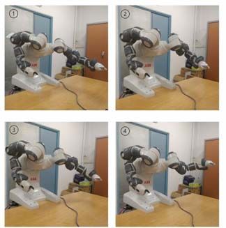
A synchronized-HRC pick and place application
using an intelligent vision system
Rainer Müller Nishant Ketan Gajjar Ahmad El Masri
ZeMA -Zentrum für Mechatronik und ZeMA -Zentrum für Mechatronik und ZeMA -Zentrum für Mechatronik und
Automatisierungstechnik gemeinntzige Automatisierungstechnik gemeinntzige Automatisierungstechnik gemeinntzige
GmbH, Saarbrücken, Germany GmbH, Saarbrücken, Germany GmbH, Saarbrücken, Germany
Khansa Rekik
ZeMA -Zentrum für Mechatronik und
Automatisierungstechnik gemeinntzige
GmbH, Saarbrücken, Germany
Abstract—In recent times, automation has been one of the Physical interaction between humans and automatons is
most important aspects of industrial applications. Collaboration unavoidable in most of the cases and even looked-for when
between the humans and robots has been a key factor for the they share a common workplace or even work hand in hand.
development of industries of the future where mutually, humans Some of our goals regarding the safety aspect of the whole
and machines, can work and carry out important tasks together.
The focus of this work is to create a method for Human-Robot
systems include developing a sensor system that monitors
Collaboration (HRC) application, with the goal of setting up workplaces and detects contact between humans and robots
robots with certain safety measures in such a way that it actively even before it happens [3]. Along with that the usage of
supports a human completing it. The paper starts with an manipulator ensures safety during interaction and cooperation
introduction to synchronized human-robot collaboration and the with humans without conventional separating barriers and
safety aspect of the system. It is then elaborated by an extensive lastly, testing the whole arrangement, sensors and controllers
study on image processing and application of computer vision used for use in shared work areas.
here in order to accomplish a given set of tasks. Using image processing along with robotics, is widely used in
recent times and has added a lot of opportunities in
productions. Considering the complications and monotony,
Keywords—Synchronized-HRC, Safety, Pick and Place, using robots for this process is effective and shows to be
Computer vision enhancing productivity. Sorting is not an easy process rather
it requires a number of complicated steps which include detail
I. INTRODUCTION extraction, detection, training the data and at last processing.
Human-Robot Collaboration as the name suggests, is the The set of objects that have to be sorted are pre-trained to the
process in which both humans and robots work and interact computer that is controlling the camera. This helps in the
with each other, without the need of any physical barriers detection of these articles from the rest. The object locations
between the work areas. This increases the productivity by and orientations are then sent to the controller, which in turn
combining human’s ability to judge, react and plan, along with will then use this position to pick up the desired object and
the robot’s capability to do repetitive and risky tasks. It place it in a predefined location.
permits human operators to pay attention to operations with This work is divided into four main parts. First, the paper gives
high added value or demanding high levels of adroitness, thus an overview about the safety aspect of human-robot
freeing them from monotonous or potentially dangerous collaboration in our trials. In the second part, the detailed
situations [11]. With collaborative robots being introduced to theory behind the computer vision and image processing part
assembly lines, manipulators are able to work in closer in our setup is expounded, followed by a brief analysis of
approximation with human operators to a point that tasks or training and processing involved. Finally, the paper is
stages in the assembly process have their roles overlap. concluded by giving a brief idea about the future works and
Human and manufacturing errors are important factors to take the system in whole.
into account, nonetheless, with the preprogrammed nature of
II. SAFETY ASPECTS OF THE SYNCHRONIYED COLLABORATION
manipulators it would be impractical to implement a
collaborative system without the use of sensors that account A. Synchronized-HRC
for such errors and make the handling of the task robust. Since the very introduction of modern robotics, a large amount
For the collaboration between humans and robots, safety and of attention has been given to the safety pertaining to the
interaction are the key factors for it to be successful. Before Human as well as the robot. Conventional industrial robots are
carrying out any given set of tasks, the safety of human beings enormous, heavy and can move about at high speeds. These
and the equipment in use around the machines should be conditions make it necessary to prevent collisions between the
guaranteed as it is quite essential even if the collaboration is robot and a human who may enter the robot workspace, to
not effective [18]. HRC-capable robots or cobots [17] as we avoid harm to the individual. The approach set by the previous
call them, offer great flexibility and can work without safety standard [1] to avoid such collisions or other occurrences that
apparatus in many applications, however, a certain level of may result in injuries, was to establish an obligatory
collaboration can still be achieved without necessarily using separation between human and robot workspaces, by detecting
them. human interruptions in robot workspaces, and adjusting the
robot actions accordingly.
14You can also read