EXCON 2019 TMAL02 EXPERT CONFERENCE - EXPERT CONFERENCE THE 4TH AIRCRAFT AND VEHICLE DESIGN STUDENT
←
→
Page content transcription
If your browser does not render page correctly, please read the page content below
ExCon 2019
   TMAL02 Expert Conference
The 4th Aircraft and Vehicle Design Student
             Expert Conference
  Linköping University, Fluid and MEchatronic Systems (FLUMES)
                14th October 2019, Campus Valla, Linköping
Proceedings of the 4th TMAL02 Expert Conference
October 14, 2019, Linköping University, Linköping, Sweden

Editor:
Dr. Ingo Staack

Published by:
Linköping University Electronic Press

 Series:          Linköping Electronic Press Workshop and Conference Collection No. 8
 ISBN:            978-91-7929-892-0
 URL:             http://www.ep.liu.se/wcc_home/default.aspx?issue=008

Organizer:
Dr. Ingo Staack
Division of Fluid and Mechatronic System (FLUMES)
Department for Management and Engineering (IEI)
Linköping University
58183 Linköping

Sponsored by:

Swedish Aeronautical Research Center

Conference Location:
Linköping University
Campus Valla / Key-building, KEY1
58183 Linköping
Sweden

Copyright © The Authors, 2019
                         This proceedings and the included articles are published under the
                         Creative Commons license Attribution 4.0 International (CC BY 4.0),
                         attribution and no additional restrictions.

                          Proceedings of the 4th TMAL02 Expert Conference 2019                 2
Editor´s Note
Stay curious and combined with a high-quality education you will become a good engineer!

This is now already the fourth time that the TMAL02 Expert Conference has been held as a part of the
Aircraft and Vehicle Design (TMAL02) course at Linköping University. This course is one of the primer
courses within the International Aeronautical Master Programme (AER) which was established in
2013 at Linköping University.

To show, analyse and explain the broad spectrum of aeronautical engineering topics ranging from basic
physical effects to operational aspects, from state-of-the-art designs to novel concepts, and all kind of
engineering domains included within aeronautical product development from the first idea to the final
flight testing campaign, requires a sound and as complete as possible background of the involved
actors. Making use of a conference with presentations and the proceedings written from students for
students is a very suitable way of exploring new fields by the students on their own.

The 4th Expert Conference is the first time the proceedings of the Expert Conference are being
published. Like in any reviewed conference proceedings, the students went through a whole review
process, acting on their colleagues as blind reviewers. Not an easy task beside all the other duties in
the tight curriculum. But as the organizer it is a pleasure to see the enthusiasm and curiosity, the time
spend for investigations, writing and the presentation preparation by the students. This year, two
students (Harmen Punte and Machiel Overmars) even created a video presentation explaining the
Coandă effect*. This and no less than seventeen other interesting topics can be found in this
proceedings.

Enjoy reading this proceedings and stay curious!

                 Dr. Ingo Staack

                      Division for Fluid- and Mechatronic Systems
                      Department for Management and Engineering
                      Linköping University, Sweden

*: Available at YouTube, see https://www.youtube.com/watch?v=oNLfg2v7ySg&feature=youtu.be

                         Proceedings of the 4th TMAL02 Expert Conference 2019                               3
Proceedings of the 4th TMAL02 Expert Conference 2019 4
CONTENTS
Aerodynamic
Coandă Effect 7
Forward-swept Wings 11
Albatross Flight: Dynamic Soaring 15
Lift Generation of Forward Flying Helicopters/Rotors 17
Supersonic & Space
Concorde 2.0 : Ongoing Supersonic Projects 21
Hypersonic Flight 25
Aircraft-based Rocket Launch 29
Sabre-Rocket 31
Vertical Landing Rockets 33
SPECIAL Topic 2019
When Do I Need to Change a Part? – Lifetime Analysis of Dynamic Helicopter 35
Components
Atmosphere
Cloud and Weather Phenomena based on the Temperature Gradient 37
Novel and Unconventional Concepts
Box-Wing Configurations: A Future Scenario? 41
A Study on Flight Mechanics of Tailless Aircraft 43
Unconventional Take-off and Landing Methods 47
Electric Vehicle Concepts
Electric Flying Vehicles 51
Electric Aircraft: Alternative Power Sources 55
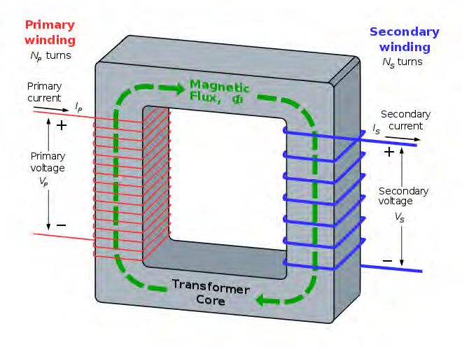
Contactless Energy Transfer Systems 57
Electric Cars or Trucks with Just-in-time Energy-Reception 61
Proceedings of the 4th TMAL02 Expert Conference 2019 5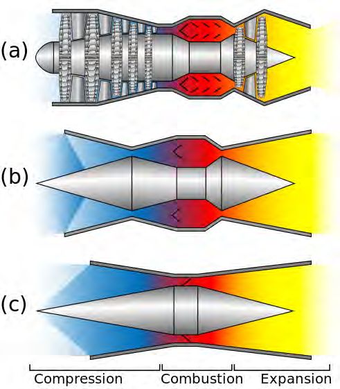
Proceedings of the 4th TMAL02 Expert Conference 2019 6
TMAL02 Expert Conference 2019

                                                Coandă effect
                                            H.J. Punte, M.A. Overmars

                       Keywords: H. Coandă, Coandă effect, V/STOL, ACHEON, NOTAR.

1   Introduction                                            trainment, see Figure 1a. The suction of surrounding
The Coandă effect is a phenomenon used in several          fluid along with the jet causes the Coandă effect [11].
applications such as health care, robotics and aero-        In case the jet is in the vicinity of a surface, a wall jet,
nautics [1, 2]. However, this effect is often interpreted   this entrainment is restricted. As a consequence, the
incorrectly. The aim of this paper is to explain the        fall in pressure cannot be compensated with surround-
Coandă effect and elaborate on the working principle       ing particles, causing the jet to deflect towards the sur-
behind it. In section 3 the common definition is given      face and eventually attach to it, see Figure 1b and Fig-
and additions are made to replenish it. It is explained     ure 1c [6, 10, 12]. The second addition to the earlier
when the Coandă effect is applicable for airfoils and      mentioned general explanation is the shape of the sur-
finally, in section 4, some applications in modern-         face, which can either be straight or convex [4, 11].
day aeronautics are presented, for example V/STOL,
ACHEON and NOTAR.

2   Background
Henri Coandă (1886-1972) was an inventor and engi-
neer born in Romania. In 1910 Coandă build arguably
the first jet plane, the Coandă-1910 [3]. However, this
plane caught fire and Coandă noticed that the flames
followed the surface of the fuselage [3, 4]. Thomas             (a) Entrainment of stationary fluid with free jet [13].
Young also noticed this phenomenon with a candle
in 1800 [5, 6]. But the crash of the plane caused
Coandă to do extensive research which resulted in sev-
eral patents and getting the Coandă effect officially
recognized by Theodore von Kármán in 1934 [7, 8, 9].
                                                                (b) Entrainment of stationary fluid with wall jet [14].
3   Description
The most common explanation for the Coandă effect
is the tendency of a fluid jet to attach to an adjoin-
ing surface [4, 6, 10, 11, 12]. Yet, certain additions            (c) Jet flow profile as a result of Coandă effect [15].
should be made to this explanation to make it com-
plete. First of all, the Coandă effect will still occur           Fig. 1 : Diagrams illustrating the Coandă effect
when the surface is removed. A free jet in a stationary
fluid, so without a surface in the vicinity, drags along    However, it is of great importance not to confuse the
some of that stationary fluid. This results in an in-       Coandă effect with the flow following a curved sur-
crease of the fluid’s velocity around it. Since momen-      face on a regular aircraft airfoil. The air around an
tum is conserved, the jet will slow down as it moves        airfoil is all moving, so there is no stagnant fluid in
through the stationary fluid. The surrounding parti-        which a jet mixes. Hence, there is no suction of fluid
cles that are dragged along with the jet will result in a   replacing the entrained fluid [11, 16].
decrease in pressure around the jet. This creates an in-    Thus, the Coandă effect rarely occurs naturally on a
ward suction of the particles nearby [4, 6, 10, 11, 12].    wing, but can be produced when a part of the exhaust
More and more particles are dragged along as the fluid      gasses is deflected over the wing, which could result
moves through the stationary fluid, which is called en-     in an increase of the lift by a factor of 3 [16]. These

                               Proceedings of the 4th TMAL02 Expert Conference 2019                                          7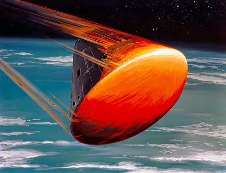
ExCon2019                                                                                                   Coandă effect

fast exhaust gasses create entrainment of the air caus-     zle and the PEACE (Plasma Enhanced Actuator for
ing a regional pressure drop and delaying separation        Coandă Effect) concept. The HOMER nozzle is a
[17]. This could be applied in the future on controlled     thrust vectoring propulsive nozzle producing a con-
surfaces of an aircraft. These surfaces are mainly di-      trollable deflection of a synthetic jet and the PEACE
mensionalized for high-lift situations and when the lift    concept extends the angle of operation of the noz-
can be increased significantly in these situations, these   zle. The integration of a HOMER nozzle with the
surfaces can be reduced in size while still being able      PEACE concept can lead to a system that is applicable
to deliver the required lift in normal operations.          in new aerial vehicles and creating new possibilities
                                                            with directionally controllable fluid jets focusing on
4     Applications                                          more sustainable and all-electric propulsion systems
                                                            [18, 23].
In the aeronautic field, new technologies should be
                                                            The original patented nozzle architecture (1), shown
designed to meet the changing demands in terms of
                                                            in Figure 2, is capable of mixing two primitive fluid
reducing environmental impact and cost while still
                                                            jets (2) and (2’) and subsequently creating an ad-
increasing the overall performance [18, 19]. As de-
                                                            justable synthetic jet (7), by changing the mass flow
scribed in section 3, the Coandă effect can be utilized
                                                            of both jets independently.
for increasing the lift of an aircraft, but can be used
in more applications. Applications discussed in this
paper are: the V/STOL aircraft, the ACHEON nozzle
and the NOTAR system.

4.1    V/STOL
Vertical and/or Short-Take-Off and Landing
(V/STOL) aircraft can introduce new and greener
technologies in aeronautics and can be very useful            Fig. 2 : ACHEON configuration defined by the patent [24].
in specific mission profiles. However, helicopters
are limited in the maximum horizontal speed and             The study performed by Trancossi et al. [19], demon-
airplanes with V/STOL have problems with the large          strated the benefits of an ACHEON based civil aircraft
weight, as a result of the mechanisms needed for            and ensuring better performance. However, this is still
tilting the engines [18]. Besides, V/STOL has been          a relatively new technology and should be further in-
introduced in the field of UAVs, being dependent on         vestigated before being implemented in commercial
the amount of energy on board. Due to the limitations       civil aircraft.
for these specific classes, a new class of V/STOL was
introduced using the Coandă Effect. The vertical and       4.3    NOTAR system
horizontal thrust in these Coandă V/STOL aircraft is
                                                            The Coandă effect is also applied in helicopters with-
generated by a central rotor fan to create a controlled
                                                            out tail rotors. NOTAR (NO TAil Rotor), developed
airflow that is vented over the fuselage. Consequently,
                                                            by McDonnell Douglas Helicopter Systems, is a sys-
low pressure around the fuselage will occur and the
                                                            tem which replaces the tail rotor and thereby elimi-
aircraft is lifted [20, 21]. These aircraft can produce
                                                            nating its mechanical disadvantage, such as noise and
maneuverability forces and lift more effective than
                                                            vibrations while also increasing safety [25].
the earlier described V/STOL aircraft [21].

4.2    ACHEON
The Aerial Coandă High Efficiency Orienting-jet
Nozzle (ACHEON) project investigates a new propul-
sive system for aircraft with the main advantage be-
ing able to deflect the trust only by fluid-dynamic ef-
fects without any part in movement [18, 19, 22]. This
trust vectoring is largely realized by making use of
the Coandă effect. The ACHEON concept is based
on two technologies: the HOMER (High-speed Ori-
enting Momentum with Enhanced Reversibility) noz-                 Fig. 3 : Configuration of a NOTAR tailboom [25, 26].

                               Proceedings of the 4th TMAL02 Expert Conference 2019                                       8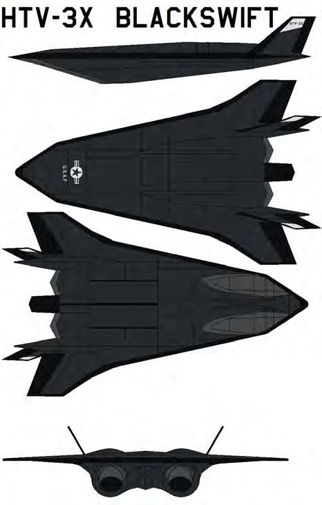
Coandă effect

NOTAR, as shown in Figure 3, uses a fan inside the                      [10] Amit Bardia, Rabya Saraf, Andrew Maslow, Kamal Khab-
tail boom forcing an airflow to exit through two lon-                          baz, Feroze Mahmood. The Coanda Effect, 2016.
gitudinal slots, creating a boundary layer flow and                     [11] Aaron K. What are the differences between Bernoulli’s
                                                                               Principle and the Coanda effect when we apply them on
utilizing the Coandă effect. This effect changes the                          aircraft wings? - Quora.com, 2017.
direction of the airflow around the tail boom, creat-                   [12]   Reba I. Applications of the Coanda Effect. Scientific Amer-
ing an anti-torque to the torque effect impaired by the                        ican, vol. 214, no. 6, pp. 84–93, 1966.
main rotor. However, directional control is still ac-                   [13]   Cruithne9. Coanda Effect 1, 2016.
complished by a rotating direct jet thruster and the                           URL https://commons.wikimedia.org/wiki/File:
thrust created by the Coandă effect acts mainly as a                          Coanda_effect_1.jpg
stabilizer [27].                                                        [14]   Cruithne9. Coanda Effect 2, 2016.
                                                                               URL https://commons.wikimedia.org/wiki/File:
                                                                               Coanda_effect_2.jpg
5     Conclusion                                                        [15]   Cruithne9. Coanda Effect 3, 2016.
                                                                               URL https://commons.wikimedia.org/wiki/File:
The Coandă effect is a phenomenon which can be                                Coanda_effect_3.jpg
used in a widespread of applications. It is commonly                    [16]   ARMD. Foam Wing (ARMD Resources - Museum in a
known for creating extra lift over the airfoils of air-                        Box).
planes. Besides this application, the effect can also                   [17]   Hong S J and Lee S H. A Study on the Flow Characteris-
have other uses within aeronautics. Such as: V/STOL,                           tics around a Coanda Control Surface. Journal of Ship and
                                                                               Ocean Technology, vol. 8, no. 2, pp. 13–19, 2004.
where the Coandă effect is used in a new type of air-
                                                                        [18]   Páscoa J C, Dumas A, Trancossi M, Stewart P and Vucinic
craft to generate lift in an effective way; ACHEON,                            D. A review of thrust-vectoring in support of a V/STOL
which is a new propulsion system where the direction                           non-moving mechanical propulsion system. Central Euro-
of the thrust can be regulated creating possibilities for                      pean Journal of Engineering, vol. 3, no. 3, pp. 374–388,
electric propulsion systems in aerial vehicles and the                         2013.
NOTAR system, a system in helicopters where the tail                    [19]   Trancossi M, Madonia M, Dumas A, Angeli D, Bingham
                                                                               C, Das S S, Grimaccia F, Marques J P, Porreca E, Smith T,
rotor has become redundant while increasing the per-                           Stewart P, Subhash M, Sunol A and Vucinic D. A new
formance. In conclusion, the Coandă effect applied                            aircraft architecture based on the ACHEON Coanda ef-
within aeronautics gives rise to better aircraft perfor-                       fect nozzle: flight model and energy evaluation. European
mances and new opportunities for more sustainable                              Transport Research Review, vol. 8, no. 2, p. 11, 2016.
aircraft.                                                               [20]   Petrolo M, Carrera E, D’Ottavio M, de Visser C, Patek Z
                                                                               and Janda Z. On the development of the Anuloid, a disk-
                                                                               shaped VTOL aircraft for urban areas. Advances in aircraft
REFERENCES                                                                     and spacecraft science, vol. 1, no. 3, pp. 353–378, 2014.
                                                                        [21]   Nedelcuţ F. Towards a New Class of Aerial Vehicles Using
    [1] Qudaisat I. Coanda effect as an explanation for unequal                the Coanda Effect. p. 8.
          ventilation of the lungs in an intubated patient? British
                                                                        [22]   Generalities | Acheon Project.
          Journal of Anaesthesia, vol. 100, no. 6, pp. 859–860, 2008.
                                                                               URL http://acheon.eu/project/
    [2]   Natarajan E and Onubogu N O. Application of Coanda
                                                                        [23]   Inside ACHEON | Acheon Project.
          Effect in Robots – A Review. Zhang T, editor, Mechanical
                                                                               URL http://acheon.eu/acheon-concept/
          Engineering and Technology, Advances in Intelligent and
          Soft Computing, pp. 411–418. Springer Berlin Heidelberg,      [24]   Baffigi F, Dumas A, Giuliani I, Madonia M and Trancossi
          2012.                                                                M. Nozzle Capable of Deviating a Synthetic Jet in a
                                                                               Dynamic and Controllable Manner with No Moving
    [3]   Coanda effect.
                                                                               Mechanical Parts and a Control System Thereof., 2013.
          URL            http://www.edubilla.com/invention/
                                                                               URL https://patentscope.wipo.int/search/en/
          coanda-effect/
                                                                               detail.jsf?docId=WO2013005132
    [4]   Ahmed N A. Coanda Effect: Flow Phenomenon and Ap-
                                                                        [25]   NOTAR R Technology - MD Helicopters.
          plications. CRC Press, 2019. Google-Books-ID: XWytD-
                                                                               URL https://www.mdhelicopters.com/notar.html
          wAAQBAJ.
                                                                        [26]   S V. NOTAR (NO TAil Rotor) System, 2007.
    [5]   Cantor G N. Thomas Young’s Lectures at the Royal Insti-
                                                                               URL       https://commons.wikimedia.org/w/index.
          tution. Notes and Records of the Royal Society of London,
                                                                               php?curid=2746196
          vol. 25, no. 1, pp. 87–112, 1970.
                                                                        [27]   Cîrciu I and Boşcoianu M. An analysis of the efficiency
    [6]   Ltd S T. Coanda Effect.
                                                                               of Coanda - NOTAR anti-torque systems for small heli-
          URL http://www.thermofluids.co.uk/effect.php
                                                                               copters, 2010.
    [7]   US Patent #2,052,869, 1936.
    [8]   Coanda H. Procédé et dipositif pour faire dévier une veine
                                                                        Copyright
          fluide pénétrant dans un autre fluide.
    [9]   Cîrciu I, Prisacariu V and Constantinescu C. Gas Turbine
                                                                                       c H.J. Punte and M.A. Overmars, 2019.
          Mixed Jet Flows Based on the Coandă effect. 2015.

                                       Proceedings of the 4th TMAL02 Expert Conference 2019                                              9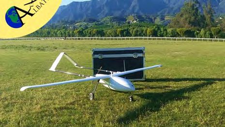
Proceedings of the 4th TMAL02 Expert Conference 2019 10
TMAL02 Expert Conference 2019

                                          Forward-swept Wings
                     Fredrik Lundvall, William Yachnin, Julien Perroud, Karl-David Läpple

                  Keywords: forward-swept wing, FSW, aerodynamics, instability, Grumman X-29.

Nomenclature                                                 reinforced. An ASW will have the opposite effect and
                                                             decrease the forces working on the wing. [4]
    Designation    Denotation
                                                             3   Inward Spanwise Flow & Stall Characteristics
 ASW               Aft-swept wing
 FSW               Forward-swept wing
 AOA               Angle of attack
 DFBW              Digital fly-by-wire
 CG                Aircraft center of gravity

1     Introduction
This article was written for an expert conference at
Linköpings Universitet. In this short article the con-
cept of forward-swept wings will be explained and                Fig. 1 Comparison of airflow of an FSW and ASW.[5]
some of its benefits and shortcomings presented.
                                                                  An important aerodynamic property of an FSW
2     General Characteristics                                is its stall characteristics. Wing-sweep in either di-
                                                             rection retards the effect of wave drag by reducing
2.1    Packaging
                                                             the effective thickness-to-chord-ratio [6]. Both ASW
A FSW has the wing-fuselage juncture much further            and FSW divide the free flow into chordwise flow and
towards the rear of the air-craft which could improve        spanwise flow. An ASW has its spanwise velocity
flexibility with the internal packaging [1]. This was        component directed towards the wing tip, in turn cre-
the idea behind the Junkers Ju 287 which was able to         ating a thicker boundary layer at the tip compared to
accommodate a bigger bomb bay in its fuselage as it          the wing-root, which, could lead to a tip-stall and loss
was not disturbed by wing or gear structures which           of aileron-control at high AoA. In contrast, spanwise
were located further back [2].                               flow over an FSW is directed toward the wing-root
                                                             resulting in a root-stall, thus leading to more maneu-
2.2    Aeroelasticity                                        verability at early onsets of stall compared to an ASW
A reason why forward-swept wings are not seen very           [4]. A clear visualisation of the oncoming airflow for
often nowadays is their aeroelastic behavior. During         both ASW and FSW can be seen in figure 1.
climb when the free-stream hits the wing tips they                A result of FSW design is a reduction in drag (due
twist up. This leads to even more lift which promotes        to weaker wing tip vortices) and higher lift which al-
the described effect even more [1]. To be able to resist     lows a design with smaller wings. The higher lift can
the high aerodynamic forces an FSW needs to be very          be explained by the fact that there is a better airflow at
rigid. This can be obtained through using compos-            the wing root which in general has a larger chord and
ite structures. Today it is even possible to design the      can therefore produce more lift than the wing tips.
aeroelastic behavior of a wing which is called aeroe-             Moreover, the locations of the stall (tip-stall for
lastic tailoring [3].                                        an ASW and root-stall for a FSW) can cause further
     FWS have higher loads during high AoA com-              aerodynamic issues. Since the CG is in front of the
pared to ASW. This is because at high AoA it forces          tip (ASW) or root (FSW) a stall will create a moment
the wing to twist up and hence increase the normal           which pitches the aircraft up, essentially progressing
force of the wing, therefore the structure needs to be       the stall even further [4]. The result is a more pro-

                                Proceedings of the 4th TMAL02 Expert Conference 2019                                  11
ExCon2019 Forward-swept Wings
nounced pitch-up effect in a FSW than an ASW due to high aerodynamic forces and have the desired aeroe-
the loss of lift at the root. lastic behavior. Especially when flying at high AoA
the aerodynamic forces on the tips of the wings are
4 Instability very high.
Most jet fighters do not have static stability which is On the other hand the DFBW ensured that the
the ability to come back to level flight position au- plane was flyable despite its extremely unstable be-
tomatically. The goal of a jet fighter is to be highly havior in pitch and yaw. The X-29 had therefore a re-
maneuverable and instability can contribute to this. If dundant system of three digital and three analog flight
an axis is unstable, only a little amount of energy is computers which made the probability of a total com-
needed to initiate a big response/ maneuver. However, puter failure as probable as the failure of a mechanical
more energy is needed to stop or reverse the deviating component on a regular airplane [7, p. 30].
motion. Instability is a question of balance between The main advantages of this concept were the ca-
being able to make rapid extreme maneuvers and the pability to fly at high AoA (approx. up to 60 ◦ ) while
ability to keep control of the aircraft [7]. Therefore, maintaining good maneuverability and controllability.
a lot of very quick adjustments must continuously be In addition to that the design of the X-29 which com-
made by the aircraft to keep control. bined canards with a FSW reduced drag and as a result
of this also fuel consumption [7, p. 18].
4.1 Pitch Instability
Generally with FSW, the center of pressure is ahead
of the CG due to wing root being further back on the
fuselage. This usually demands a canard configura-
tion because the empennage would have to generate
huge downward forces to compensate for the nose-
down moment. Since both surfaces are lift surfaces,
this encourages further instability [4].
Another property that promotes the pitch instabil-
ity of FSW is the aeroelasticity of the wing especially
at high AoA which has been explained in section 2.2
4.2 Yaw Instability
FSW designs are very unstable when yawing (turning
around the horizontal axis). When the plane yaws in
one direction the inner wing retreats while the outer Fig. 2 The experimental aircraft Grumman X-29 and it’s for-
ward swept wings.[3]
advances. While retreating, the inner wings sweep
angle towards the free-stream decreases which results
in rising drag. The exact opposite happens on the
outer wing which enforces the yaw instability. An 5 Discussion
ASW configuration in contrast will stabilize itself dur- The concept with FSW is an interesting one and has its
ing yawing. This is because the advancing and the re- advantages and disadvantages. Nowadays, we should
treating wing are just swapped compared to the FSW have the technological means to solve the problems
which leads to aerodynamic forces that push the plane that were encountered with FSW. As seen, FSW of-
back into stable flight [8]. fers advantages in high maneuverability and good stall
characteristics. However, FSW are not the only ap-
4.3 Case Study: Grumman X-29 proach to make a plane more manoeuvrable. Thrust
The Grumman X-29 is probably the most famous ex- vectoring is used a lot in fifth generation fighters and
ample of a supersonic FSW aircraft. There were es- is a proven concept for example. This does not mean
pecially two factors that made the development of the that we will not see this technology in future concepts,
X-29 possible in the early 1980s: DFBW and com- it will depend on what the requirements of the indus-
posite structures [7, p. 5]. try will be, like stealth (radar cross section depends
The composite structures have been needed to a lot on the geometry of the aircraft) or ability to fly
build a wing that is rigid enough to withstand the unmanned missions.
Proceedings of the 4th TMAL02 Expert Conference 2019 12Forward-swept Wings
REFERENCES
[1] Anderson, John David, Jr. Introduction to flight. 8th ed.
Boston: McGraw-Hill, 2016.
[2] Flying Review International Vol 20 , Number 4: 43–45 Jan
1965 (2:nd hand source). Swept-forward bomber.
URL
https://en.wikipedia.org/wiki/Junkers_Ju_287
[3] NASA. X-29 in banked flight.
URL https://www.nasa.gov/centers/armstrong/
news/FactSheets/FS-008-DFRC.html
[4] Bertin, John J Cummings, Russell M. Aerodynamics for
Engineers. 8th ed. Pearson Education Limited, 2014.
[5] NASA. Quest for performance: The evolution of modern
aircraft:wings and configurations for high-speed flight.
URL
https://history.nasa.gov/SP-468/ch10-4.htm
[6] Staack, I. 2019-09-18. Lecture 8: Aircraft Performance,
Linköping University.
[7] Johnsen F A. Sweeping Forward. National Aeronautics and
Space Administration, 2013.
[8] J, Miller (2:nd hand source). forward-swept wings.
URL https:
//en.wikipedia.org/wiki/Forward-swept_wing
Copyright
c The Authors, 2019.
Proceedings of the 4th TMAL02 Expert Conference 2019 13Proceedings of the 4th TMAL02 Expert Conference 2019 14
TMAL02 Expert Conference 2019

                                 Albatross Flight: Dynamic Soaring
                                            Alice Haultcoeur, Benoit Ingouf,
                                               Florent Bel, Yvan Pradier

           Keywords: Albatross, Bird flight, Soaring flight, Dynamic soaring, Airspeed, Biomimetics

ABSTRACT                                                      data [1]. The albatross flight cycle can be separated
This article presents the flight of an albatross, and         in four phases (Fig. 2).
more precisely the survey of the dynamic soaring. It
is the flying technique used by the bird to save energy.

1   Introduction
With its 10 kilograms and its 3-meter-wide wings, the
wandering albatross can spend weeks at sea without
ever returning to land (Fig. 1). It allows the bird to
fly for long distances without using a lot of energy
and moving its wings, it is an unflapping flight. The
albatross can fly in each direction, even against the
wind easily. It operates in the shear wind field, an                     Fig. 2 The Albatross flight cycle [2]
area of 10 to 20 meters above the surface of the ocean
where the wind speed changes dramatically. Close to               The mechanism is simple, it is based on a cycle
the water, the wind speed is dramatically reduced by          that it repeats again and again to gain energy and
friction.                                                     travel laterally to the wind direction. Each time it
                                                              does the cycle, it starts with more ground speed and
                                                              airspeed. The albatross can use this technique because
                                                              a phenomenon appears close to relief and close to
                                                              the water surface. Near the surface, there are two air
                                                              masses with different velocities called wind gradient
                                                              zones. (1) The first phase is the windward climb.
                                                              The bird goes through the boundary between the two
                                                              layers to gain energy. Facing the wind, the albatross
                                                              gains a bit of altitude. (2) The second phase begins
                                                              at peak altitude, after crossing the boundary between
                                                              the two air masses. The bird describes a curve from
                                                              upwind to downwind, it turns. (3) Then, the third
                                                              phase is descending in wind direction, gaining speed
               Fig. 1 Albatross in flight [5]
                                                              and crossing once again the two gradient zones. (4)
                                                              Finally, the last phase of the albatross flight cycle is
                                                              close to the water. The albatross turns in the reverse
2   Dynamic soaring                                           direction to face the wind and start the cycle again.
The flight technique used by the bird is known as dy-
namic soaring which allows it to extract energy from              When it is performing dynamic soaring, the alba-
the shear wind [2]. Albatross use the wind lift as            tross does a series of 180◦ turns so its path looks like
a propulsive force. This propulsive energy is just            a S-shaped maneuver. Moreover, the albatross can
enough to overcome the winds drag. To improve the             use these techniques because it has a specific shape
notion of dynamic soaring, scientists are using GPS           and the ability to lock its wings when it is soaring in
tracking to analyse albatross flight and wind speed           order to avoid muscle tension. This technique is used

                                 Proceedings of the 4th TMAL02 Expert Conference 2019                               15
ExCon2019 Albatross Flight
by gliders, but they fly in circles and not two rotations designed and commercialized since 2015: The Alba-
of 180◦ in opposite directions. Wind gradients are tross UAV by Applied Aeronautics (Fig. 3). With its
more important when the glider performs it than three-meter-wings and its ten-kilogram-MTOW, the
when the albatross turns close to the surface. electrical drone looks like the seabird. Every com-
ponent is designed in order to reduce the drag and
A research made by Philip L. Richardson, Ewan improve the efficiency of the cruise. The drone can
D. Wakefield and Richard A. Philips on the subject take-off, fly and land autonomously for 4 hours. The
“Flight speed and performance of the wandering al- Biomimetics is very present in this innovation.
batross with respect to wind” has provided interesting
results [1]. During this research, the Leeway model, 4 Conclusion
the airspeed model, the ground speed model and other To conclude, the dynamic soaring could be an inter-
relations have been found and defined. These seabirds esting technique for airplane because it uses the wind
regulate their velocities in relation to wind speed and energy to rise in the air. Whereas, it can not be used
relative wind direction. When the wind blows below by civil or military airplane because the travel time
7 m/s, the optimal range speed of albatrosses is much would be too long.
higher when they fly upwind than for tailwind flights.
REFERENCES
3 Biomimetics
[1] Philip L. Richardson, Ewan D. Wakefield and Richard A.
Biomimetics is used by designers to help in solv- Philips. Flight speed and performance of the wandering
ing human problems by creating nature-inspired solu- albatross with respect to wind. In: Movement Ecology 6
tions. In addition to this mechanism, albatrosses have (2018), Article 3.
ISSN: 2051-3933. DOI: 10.1186/s40462-018-0121-9.
the ability to lock their wings at the shoulder for long- eprint: https://rdcu.be/bSE9Y.
distances soaring and unlock them when turbulence URL: https://movementecologyjournal.biomedcentral.com
or gusts arise or when they need to maneuver. This /articles/10.1186/s40462-018-0121-9
trick allows the bird to reduce the drag and the effects [2] Johannes Traugott, Anna Nesterova and Gottfried Sachs.
of turbulence drastically. In that way, albatrosses can The Nearly Effortless Flight of the Albatross.. IEEE Spec-
trum. [Online; accessed 2013-06-28]. 2013.
fly many kilometres without spending much energy URL: https://spectrum.ieee.org/aerospace/
[3]. It has inspired airlines companies such as Air- robotic-exploration/the-nearly-effortless-flight
bus which have the ambition to develop new wings -of-the-albatross
with movable tips called “freely-flapping wing-tips". [3] Airbus Website, How the albatross is inspiring next genera-
Currently as a model, the AlbatrossOne project would tion of aircraft wings.,
https://www.airbus.com/newsroom/press-releases/en/
permit to cut down the drag forces, and thereby, in- 2019/06/how-the-albatross-is-inspiring-next-
duce lower loads transmission in the fuselage. The generation-of-aircraft-wings.html
wing would not need to be heavily strengthened any- [4] Kicstarter, The Albatross UAV
more. Therefore, it would be possible to decrease the https://www.kickstarter.com/projects/
aircraft weight and reach better fuel efficiencies. 164361630/the-albatross-uav?lang=fr
[5] Pixabay, Albatross in flight
https://pixabay.com/fr/photos/albatros-de-
laysan-oiseaux-de-mer-848343/
Copyright
c Alice Haultcoeur, Benoit Ingouf, Florent Bel,
Yvan Pradier, 2019.
Fig. 3 The Albatross UAV [4]
Albatross shape and dynamic soaring are not only
used to design wings of different airplanes. A drone
completely inspired from the albatross flight has been
Proceedings of the 4th TMAL02 Expert Conference 2019 16TMAL02 Expert Conference 2019
Lift generation of forward flying helicopters/rotors
Agustín Monzón, Balamurugan Gunasekar, Daniel Hernández, Sanjay Nambiar
Keywords: Helicopters, Aerodynamics, Lift, Rotors, Forward, Flight.
1 Introduction The weight of the helicopter on the other hand is
a fixed downward force that pulls the aircraft towards
This paper gives a fundamental introduction to the
the ground due to the force of gravity. Thrust is a
lift generation in forward flying helicopters and rotors.
forward force produced by the propeller or rotor sys-
The paper proceeds by introducing the concept of ba-
tem. The tail rotor also generates a small portion of
sic lift generation in helicopters and the role of blade
thrust, used to control the helicopter’s yaw. Drag, on
orientation in lift generation. Then a brief description
the other hand is a resistance force to the helicopter’s
about a forward flight of helicopters with comparison
movement through the air and caused mainly by the
to different rotor configurations are presented to un-
interference of aircraft components CDo and lift gen-
derstand the lift generation influenced by the different
eration CDi (see Figure 1). [1]
rotor configurations. Finally the paper discusses the
complexity involved in the forward flight and possi-
3 Forward flight
bly discuss some futuristic ideas to overcome these
convolutions in lift generation of forward flying heli- For the helicopter to be in forward flight the main
copters. rotor must be tilted, which will induce a tilt in the con-
ing axis backward and angled to the advancing side of
the rotor. With the increasing coning angle, there will
2 Basic Aerodynamic forces be an increment in the flapping angle. With higher
As soon as the helicopter lifts off the ground, the flapping motions, there will be an increase in the back-
interaction of the geometry and velocity of the aircraft ward tilt of the cone axis, which will boost the longitu-
with the flow field generates four aerodynamic forces: dinal force and thereby restricting the forward flight of
lift, weight, drag and thrust. In helicopters, the the helicopter. So, the flapping motion is restricted by
lift force is generated due to the sudden change in the centrifugal forces and flapping compensator. [2]
direction of the fluid flow caused by the aircraft’s
3.1 Airflow in forward flight
rotor blade. The majority of this lift force is generated
due to the result of decline in pressure above the rotor In forward flight, air flows opposite the aircraft’s
blade, rather than the high pressure developed at the flightpath, so the velocity of the airflow is equal to the
lower surface of blade. velocity of the helicopter in forward flight. However,
relative velocity at each section of a blade will vary
in accordance with different positions in a rotor disk.
LIFT
[3]
Therefore, the airflow meeting each blade varies
continuously as the blade rotates. The highest veloc-
ity of airflow occurs over the advancing side of the
helicopter, because the velocity of the air meeting this
THRUST DRAG
blade equals rotational velocity of the blade plus wind
velocity resulting from forward airspeed, so the low-
est airflow velocity is in the retarding side (see Figure
2). This is known as dissymmetry of lift, so if this dis-
WEIGHT symmetry were not controlled, the helicopter would
be uncontrollable when there was wind. So the ques-
tion is: How can avoid this dissymmetry?
Fig. 1 Aerodynamic forces
Proceedings of the 4th TMAL02 Expert Conference 2019 17ExCon2019 Lift generation of forward flying helicopters/rotors
Because of changing AOA, every blade generates
different angular velocities which contributes to varia-
tion in the rotor rpm, and it should be compensated. A
great solution is to generate a proportional alternation
in power so that the rotor rpm keeps constant. Nowa-
days, a throttle control or a governor is implementing
in helicopters so they can alternate its power automat-
ically. [5]
Fig. 2 Airflow forward flight.
The aerodynamic forces can be improved by
changing the angle of attack of blades called feather-
ing, which can be done in collective or cyclic manner.
Dissymmetry of lift in the advancing and retarding
side of rotor disk is compensated by coupling of
cyclic feathering and flapping mechanism of the Fig. 3 Collective and cyclic pitch.
blade. [4]
In addition when the blade flaps upward (caused 4 Types of rotors configuration in forward flight
by the higher speed on the right side of the heli-
copter), the angle between the chord line and the There are three different configurations by which
resultant relative wind decreases. This decreases the helicopters can generate thrust: semirigid, rigid and
AOA, which reduces the amount of lift produced by fully articulate rotor system (see Figure 4).
the blade. In this way, the helicopter is able to make
an advance flight where the lift is the same throughout The semirigid configuration is capable of flying
the helicopter. forward with a two blades mounted rigidly to the
main rotor since it is free to tilt and a feathering
hinge provides blades to change its pitch angle. Then,
the rigid configuration is structurally complex since
3.2 Blade orientation in forward flight
blades are rigidly attached to the main rotor hub.
Helicopter’s blades are basically wings, so they Thus, loads must be absorbed by bending as there are
have to change its pitch in order to vary its angle no hinges to do it, but the blade bending also provides
of attack and, then, generating forwards motion. the motion of the helicopter. On the other hand, this
There are different kinds of configurations in order to configuration is easier to design.
achieve these phenomena: by tilting the rotor hub or
by tilting each blade. Both configurations have the Finally, the fully articulate configuration lets each
same cons: (see Figure 3) blade an almost free motion since it can lead, flap
and feather self-reliant. On this configuration, these
When the AOA of a blade increases, lift also three degrees of freedom of each blade provides the
increases and revolution of the rotor decreases. Thus, pitch, roll and upward motion. But, this configuration
for a forward flight, the AOA on the advancing blades is quite more complex to design than the others since
must decrease and the AOA on the retreating blades blades must change constantly its pitch, yaw and roll
must increase. angles while rotating in order to generate motion.[6]
Proceedings of the 4th TMAL02 Expert Conference 2019 18Lift generation of forward flying helicopters/rotors
REFERENCES
[1] Leishman J G. Principles of helicopter aerodynamics. Cam-
RIGID ROTOR bridge University Press, 2006.
MAIN ROTOR BLADES
[2] D B. Helicopter Aerodynamics. National Aeronautics and
Space Administration, 1972.
[3] Ángel Cuerva Jose Luis Espino Óscar López Jose
Meseguer Álvaro Sanz. Teoría de los Helicópteros. Iber-
MAIN ROTOR garceta Publicaciones S.L, 2012.
SEMI-RIGID ROTOR FULLY ARTICULATED ROTOR
[4] Johnson W. Helicopter Theory. Dover Publications, INC,
LEAD/LAG HINGE 1980.
[5] Rotaru C and Todorov M. Helicopter Flight Physics. 2017.
[6] Administration F A. Helicopter Flying Handbook. U.S De-
FEATHERING HINGE
PITCH HORN BLADE PITCH HORN partment of Transportation, 2012.
PITCH CHANGE LINK
Fig. 4 Types of rotors configuration.
5 Conclusions
One of the major complexities in forward flight
is the dissymmetry of lift, where the lift generated
on the opposite sides of the rotor disc are uneven.
This phenomenon of dissymmetry causes retreating
blade stall, where the retreating blade experiences
less airflow than expected to maintain lift. In modern
helicopters to reduce the dissymmetry of lift, the
mounting of rotor blades is oriented in such a way
that in a rotor cycle, the angle of attack varies with
the position. Even, the above-mentioned techniques
of “blade flapping” and “cyclic feathering can be used
to counter the dissymmetry effects.
Finally, in order to conclude this report, a forward
sight in history is going to be done so that some ideas
of what is coming up are projected. The futuristic in-
novations in helicopters focuses to infuse the ideas
of lift and forward thrust. Some important research
ideas include vertical take-off, hovering and attain-
ment of fast cruise speeds by propellers in helicopters.
To achieve these ideologies, the design characteristics
must undergo some innovative modifications like ad-
dition of a fixed wing, box wings, larger diameter of
rotors, lateral propellers, elimination of the tail rotor
etc. Another major innovation is the morphing rotor
blade twist geometries, which aims at the lift distri-
bution variation along the spanwise direction with-
out affecting the pitching moment. All these inno-
vative ideologies signifies the vast scope for further
research in lift generation strategies in forward flying
helicopters/rotors.
Proceedings of the 4th TMAL02 Expert Conference 2019 19Proceedings of the 4th TMAL02 Expert Conference 2019 20
TMAL02 Expert Conference 2019

                      Concorde 2.0: On-going Supersonic Projects
                            Florian Böhme, Samuel Cadete, Grégoire Dannet

                                      Keywords: supersonic, projects, future.

ABSTRACT                                                    This led to many advantages like saving a lot of
This report serves to inform about, which role super-       weight and making the plane safer. [3]
sonic projects will play in the future of aviation.         If the airplane was such a milestone in aircraft engi-
Therefore, two recent projects, which shall bring back      neering, it makes sense to search somewhere else for
the former euphoria for supersonic transportation get       the reason why it failed.
shown.
But first of all the Concorde, which was the only           1.2    Different problems
commercial used civil supersonic aircraft gets ana-         In many people’s opinion the retirement was caused
lyzed to work out, why supersonic transportation got        by the fatal accident in 2000, but in fact the airlines
forgotten.                                                  thought about stopping the use of the Concorde ear-
Having a look in the past to see, what problems the         lier. [2]
Concorde faced, makes it possible to evaluate if the        The decisive reason was that many expensive hard-
projects for the future are doing better.                   ware updates were necessary to modernize the aircraft
                                                            and the airlines decided, that this is not worth it, be-
                                                            cause of the main problems which the Concorde had.
1     The Concorde                                          [1]
The Concorde was mainly used to make traveling be-          The Concorde has the two major problems of being a
tween London and New York, as well as between Paris         very noisy aircraft with a high fuel consumption. Es-
and New York faster. Powered by four turbojet en-           pecially in comparison to the Boeing 747, the disad-
gines, produced by Rolls-Royce/SNECMA the Con-              vantages get clear. With the same fuel consumption
corde makes use of a delta-wing design. This design         the Concorde was only able to carry 100 passengers
allows to fly at a high angle of attack, which makes        whereas the Boeing has 440 seats. [4, 2]
the airplane very agile and better in terms of maneu-       In table 1, you can see that the Concorde has a range
verability than many military airplanes. [1, 2]             of around 3500 nautical miles, while the Boeing 747
                                                            had a range of 5600 nautical miles [5, 4]
1.1    High technology                                      Regarding to the noise emissions, it can be said that
                                                            these are quite high in comparison to other aircraft.
The aircraft is popular for its pioneering technology,
                                                            Especially in the take-off phase, because here the
which is common now, but at the time represented a
                                                            Concorde makes use of an afterburner. [5, 1]
world first. This includes a computer controlled air
                                                            The Concorde with a maximum take-off weight
intake system, for instance. It is needed because the
                                                            (MTOW) of 185 tons is approximately 350 EPNdB
air would be too fast for the engines to intake, when
                                                            loud, whereas a Boeing 747 with a MTOW of around
the airplane is at supersonic speeds. To avoid major
                                                            500 tons just emits a noise of 290 EPNdb. [5]
damage on the engines the Concorde is able to change
the geometric of the air inlet to slow down the air
                                                            2     Presentation of two on-going projects
stream. Because of putting air flaps into a certain con-
figuration to form a nozzle, a supersonic shock wave        After this brief presentation of the Concorde, two on-
gets produced which slows down the air. In addi-            going supersonic projects, that will be develop in the
tion, besides the Concorde, only a few airplanes were       near future (five to ten years), will be analysed. Know-
controlled by the fly-by-wire technology at this time,      ing the reason why the Concorde failed to thrive is go-
what means that the commands by the pilot go to a           ing to be useful to understand how these new projects
computer first and then to the actuators, not directly      intend to deal with the Concorde’s problems.
to them. [1]                                                     One of the first projects is called Boom (Fig. 1).

                               Proceedings of the 4th TMAL02 Expert Conference 2019                               21
ExCon2019 On-going Supersonic Project
cord engineers could only make smaller parts: car-
bon fiber, the main material used in the fuselage and
wings and some others structural parts. This material
allows a reduced weight which is a big factor to take
in consideration when developing a plane for super-
sonic flights. It will have Delta wings (as Spike will)
due to their better characteristics at supersonic speed
and a smaller size, which was one of the Concorde’s
disadvantages for its high noise or fuel consumption.
2.1.2 Engines
The prototype XB-1 will need afterburners to achieve
mach 2.2. However, due to engine improvements in
Fig. 1 Image of Boom, Overture, extracted from Boom Website
the last few years, Boom will not have the need to
[6]
use afterburners for Overture, one of the main cause
of noise pollution and a setback towards approval to
Boom is a Northern American company developing fly overland and get to a country further from the sea,
the next supersonic commercial airplane, planned to which was one of the Concorde’s problems and lim-
fly at a top speed of Mach 2.2, faster than any possi- ited it to transatlantic flights. It will have 3x non-after-
ble competitor (table 1), and promising ticket prices burning engines, a medium-bypass turbofan and pro-
comparable to a seat in business class. It can change prietary variable geometry intake and exhaust making
the transportation the way we know it. Boom is devel- it more silent, and with a fuel per seat comparable to
oping their first flight prototype, a 1/3 scale 2-seat Jet subsonic high range planes. As seen in table 1, Boom
engine named XB-1, with first flights taking place in is a optimized aircraft for the amount of passengers it
2020. Their first passenger supersonic plane, named can hold, it has the smaller aspect ratio of the three
Overture (Fig.1) is planned to arrive in the mid-20s, models analysed which contributes to a reduced sonic
after enduring some thorough examination and certi- boom. However, it is longer than Spike in order to
fication, all optimized through their XB-1 test model. carry more payloads.
The other on-going project we chose to discuss, is Furthermore, Boom is developing a sustainable
called Spike (Fig. 2). This plane is developed to be a supersonic commercial traveling, taking in consider-
business jet able to carry about twenty passengers at ation the UN’s existing goal of carbon-neutral growth
Mach 1.6. It is powered with two engines. Its design, in aviation by conducting several alternative-fuel
as seen in figure 2, has been studied to minimize the tests, and they plan to achieve environmentally and
drag. socially sustainable travel.
2.2 Spike
2.2.1 Noise
As seen earlier, one of the problem of supersonic flight
was the noise, the Concorde was not allowed to fly
at supersonic speed above land. That is why, one of
the purpose of this project is to reduce the noise in
order to fly overland and be able to reach more in-
lands destinations. Thanks to its design, Spike S-512
Fig. 2 Image of Spike S-512 extracted from Spike Website [7] (Fig. 2) will be able to have a quiet supersonic noise
at his cruising speed of Mach 1.6. This speed is lower
than the Concorde in order to improve the L/D ratio of
2.1 Boom the plane. When the speed is higher than Mach 1, as
2.1.1 Materials the mach number increases, the (L/D)max decreases
The main difference between the Concorde and Boom [8].
is the technology: from computation power, aerody- In order to be quieter, supersonic planes need to
namics, new materials, engine improvements. Boom’s have an optimized aerodynamic fuselage, from the
SST will be mainly built from a material which Con- front to the back. Comparing the length of planes and
Proceedings of the 4th TMAL02 Expert Conference 2019 22On-going Supersonic Project
the numbers of passengers for each aircraft in Table aerodynamics. In order to overcome the different dif-
1, one of the conclusion is that length needs to in- ficulties brought by the Concorde, supersonic planes
crease in order to reduce the sonic boom. However, have to respect some obligations; that is why planes
it won’t be possible to fit as many passengers as sub- tend to be smaller as seen with the projects analysed.
sonic planes can. One cannot imagine a long aircraft Moreover, to reduce the fuel consumption, as seen in
as it will require to redesign all airports so that the Boom aircraft, it is possible thanks to latest improve-
plane may fit at its gate or turn while taxing. That ments in engines and these parts of the plane would
may be one of the reason, Boom is only able to carry certainly keep improving in the future years.
50 passengers. Finally, if one wants to know if supersonic flight
would be feasible in the future, one can optimistically
2.2.2 Size say yes, because many projects will be developed in
Moreover, due to the high speed required, lots of the future and one of them would be profitable and re-
characteristics have to be taken into account for spectful of the different standard. However, the ticket
high-speed or high-lift aerodynamics. With the two price would certainly be more expensive than a sub-
projects developed in this paper, as seen in table 1, sonic aircraft.
the size of supersonic planes (in term of passengers)
decreases. As the most effective surface (flat plate) REFERENCES
to get the best L/D ratio has the least effective pay-
[1] Concorde. [Used on 26.09.19].
load capacity [8], that means supersonic planes will URL http://concordesst.com/
be much smaller than subsonic aircraft. [2] Engineering I. Concorde: The Real Reason Why the Super-
As one know the high fuel consumption of the sonic Passenger Jet Failed, 2017. [used on 27.09.2019].
Concorde, the future of the two on-going projects can URL https://interestingengineering.com/
be doubtful. Their L/D ratio is lower than the Con- concorde-the-real-reason-why-the-supersonic-passenger-j
corde which will certainly lead to a high fuel con- [3] Cox J. Ask the Captain: What does ’fly by wire’ mean?,
2014. [Used on 26.09.19].
sumption as well. URL https://eu.usatoday.com/story/
travel/columnist/cox/2014/03/30/
3 Tables fly-by-wire-cockpit-controls/7026935/
This table sums up the different characteristics of the [4] Boeing. Historical Snapshot. [Used on 27.09.2019].
URL http://www.boeing.com/history/products/
different planes cited in the document. As the purpose 747.page
is to present the different projects, it seems relevant to [5] de Jolimont A O. From Concorde to new supersonic aircraft
compare these data with the past supersonic plane : projects. Ancien Observatoire de Jolimont, 2019. [used on
the Concorde. 27.09.2019].
Some of the following data are likely to change as the URL https://academieairespace.com/wp-content/
uploads/2019/06/AAE_D46_UK_WEB.pdf
two projects are still being developed.
[6] Boom. Boom supersonic, 2019.
URL https://boomsupersonic.com/
Table 1 Supersonic planes characteristics [5] [7] Aerospace S. Spike s-512, 09/2019.
URL http://www.spikeaerospace.com/
Concorde Boom Spike 2
[8] Anderson, John David, Jr. Introduction to flight. 8th ed.
Nb of passengers 100 45-55 12-18 Boston: McGraw-Hill, 2016.
Cruise Mach 2 2.2 1.6
Length (m) 61.66 51 37 Copyright
Wing area (m2 ) 358 218 164
Wingspan (m) 25.6 18 17.7 c Florian Böhme, Samuel Cadete, Grégoire Dan-
net, 2019.
Range (NM) 3500 4500 6200
Aspect Ratio 1.83 1.49 1.92
Max L/D ratio 7.14 5-6 5-6
4 Conclusion
Building a supersonic aircraft is made of concessions.
Choosing to improve the supersonic rather than sub-
sonic, the high speed aerodynamics over the high lift
Proceedings of the 4th TMAL02 Expert Conference 2019 23Proceedings of the 4th TMAL02 Expert Conference 2019 24
TMAL02 Expert Conference 2019

                                            Hypersonic Flight
             Niklas Olsson , Pranav Uday Rane , Rahul Rajan Sourirajan , Kevin Savio Swamy

    Keywords: aerodynamic heating, shockwaves, hypersonic propulsion, hypersonic vehicles, re-entry vehicles.

ABSTRACT
The main areas of focus within hypersonic flight were
hypersonic propulsion and re-entry vehicles. Findings
of the study states, self sustained hypersonic flight
need an advanced engine that can function through all
Mach regimes. Aerodynamic design of re-entry vehi-
cles require a different approach compared to atmo-
spheric hypersonic flight.

1    Introduction
The first man-made object to fly hypersonic, Mach
greater than 5, was the WAC Corporal in 1949, a
rocket developed in the United States. It was part of
a multi-stage rocket, made to achieve high velocities
and altitudes. The WAC Corporal was ignited when
the first stage, a V-2 from Germany, had achieved a
velocity and an altitude of 1500 [m/s] and 161 [km]
[1].
     Russia sent the first human flying hypersonic
early 1961. The Russian made Vostok I, a space-
craft, achieved Mach 25 during re-entry into the at-
mosphere. The United States sent a human flying hy-
personic, late 1961 in X-15, a rocket powered aircraft
that achieved Mach 5. The first aircraft to exceed 1609
[km/s] (one mile per second). In 2004 the first sus-
tainable hypersonic flight was made by the Americans        Fig. 1 Lockheed HTV-3X Blackswift, available at [2] under the
with the X-43, a flight that verified predictions based     Creative Commons Attribution 3.0.
on wind-tunnel experiments as well as data from CFD.
The X-43 was a multi-stage aircraft that, after releas-     2   Hypersonic Propulsion
ing it’s booster rocket, reached Mach 10 with a scram-
jet engine [1].                                             Scramjets (Supersonic Combustion Ramjet) are used
     One clear difference between hypersonic and sub-       to fly hypersonic through the atmosphere where com-
sonic, supersonic aircraft are the integration of com-      bustion occurs at supersonic velocities. A scramjet
ponents. For regular aircraft, that is subsonic and su-     uses the speed of the aircraft to compress the air be-
personic, the different parts that they consist of are      fore combustion of the fuel to give the desire thrust.
distinct and easily identifiable. For a modern hyper-       The only downside to scramjet propulsion is the re-
sonic aircraft all the main parts are integrated in each    quirement of assisted take off to initially accelerate
other, ending up in what seems to be a flying wing [1].     the aircraft to hypersonic velocities [3].
The hypersonic technology vehicle as seen in Fig. 1              Fig. 2 shows the different power plants used
clearly shows the resemblance of a flying wing.             by aircraft in different Mach regimes, (a) represents
                                                            a typical turbo jet engine where the Mach number
                                                            is subsonic throughout, (b) represents a ramjet en-

                               Proceedings of the 4th TMAL02 Expert Conference 2019                                    25
ExCon2019 Hypersonic Flight
gine where the flow speed is reduced to subsonic be- signed with large round bluff noses in front, as seen in
fore combustion and (c) represents a scramjet engine Fig. 3. The blunt nose body will cause a bow shock
where the flow is supersonic throughout the engine. and increased drag but it will still be more optimized
in heat management [5].
Decelerating the module is a also a critical as-
pect to consider while planning the trajectory. Con-
ventional methods of deceleration using drag devices
such as parachutes will fail to work in the hypersonic
regime since the air density will be very low at high al-
titudes. Furthermore, the heat generated will burn the
tether line connecting the drag device to the re-entry
vehicle [6].
Current methods of hypersonic deceleration in re-
entry vehicles involve using the geometry of the mod-
ule itself. Atmospheric re-entry modules are typically
axisymmetric bluff bodies. These bluff bodies will
generate drag as well as significant lift when trimmed
at an angle of attack. Achieving this aerodynamic lift
component for axisymmetric bodies can be achieved
by shifting the lateral position of the Centre of Grav-
ity. This will enable the module to trim at the re-
quired angle of attack and attain better aerodynamic
efficiency (L/D). The lift component will also reduce
the loads acting on the astronauts inside the module
Fig. 2 Various power plants used in different Mach regimes. a)
Turbo Jet Engine b) Ramjet Engine c) Scramjet Engine, available [7].
at [4] under the Creative Commons Attribution 3.0.
3 Re-entry Vehicles
Hypersonic flight is also applicable to re-entry vehi-
cles, a typical Mach number for re-entry vehicles en-
tering the atmosphere is around 25. At such high ve-
locities aerothermal heating is a significant problem.
The air friction accompanied by radiative heat from
the shock layers accumulate an enormous amount of
heat on the body. In order to manage and dissipate
the heat evenly, these bodies are designed with large
curvatures rather than sharp edges [5].
Sharp nosed bodies produce less drag and reduce
the risk of a normal shock wave in front of the body. Fig. 3 A blunt nosed re-entry module entering the atmosphere
Fighter jets and missiles in the supersonic and low hy- illustrating the temperature difference along the surface [8].
personic Mach regime, as in Fig. 1, optimize their
designs based on the fact that sharp nosed bodies pro-
duce less drag. Applying this design principle to bod-
4 Conclusion
ies in hypersonic Mach regime has proven to be diffi-
cult. The oblique shock waves generated by the sharp Hypersonic flight is limited due to the available engine
edges will generate an immense amount of heat. This technology and materials. To fly hypersonic today,
heat will be concentrated locally on the edge, even- aircraft needs at least a two stage propulsion system
tually melting it. Because of the heat concentrations, to be able to reach and maintain sustained flight in
heat dissipation is quite often more critical than drag the hypersonic Mach regime. Development of engines
reduction when designing for hypersonic speed. Bod- that can operate across all Mach regimes will pave the
ies designed for high hypersonic speeds are thus de- way for hypersonic atmospheric flights in the future.
Proceedings of the 4th TMAL02 Expert Conference 2019 26You can also read