Rosemount 248 Temperature Transmitter - Emerson
←
→
Page content transcription
If your browser does not render page correctly, please read the page content below

Product Data Sheet
00813-0100-4825, Rev NC
February 2021
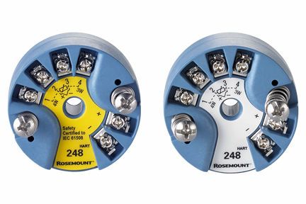
Rosemount™ 248 Temperature Transmitter
■ Basic temperature transmitter offers a reliable solution for temperature monitoring points.
■ Standard transmitter design provides flexible and reliable performance in process environments.
■ Experience lower over-all installation costs when compared to wiring sensor directly, reducing the need for expensive extension
wires and multiplexers.
■ Explore the benefits of a Complete Point Solution™ from Rosemount Temperature.
Rosemount 248                                                                                                                                                          February 2021

Features and benefits
■ RTD, TC, potentiometer, linear resistance and bipolar mV input
■ Wide ambient operating temperature of -50 to +85 °C
■ 2.5 kVAC galvanic isolation

Basic temperature transmitter offers a cost effective solution for temperature
monitoring points
 ■ DIN B style head mount transmitter
 ■ Variety of DIN B enclosure options
 ■ Rail mount
 ■ HART®/4–20 mA Protocol
 ■ Single sensor capability with universal sensor inputs (RTD, T/C, mV, ohms)
 ■ Transmitter-sensor matching with Callendar Van Dusen constants
 ■ SIL2 Capable: IEC 61508 certified by an accredited third party agency for use in
   safety instrumented systems up to SIL 2

Standard transmitter design provides flexible and reliable performance in
process environments
■ Offers improved measurement accuracy and reliability over direct-wiring a sensor to the digital control system for a lower
  overall installation cost
■ One-year stability rating reduces maintenance costs
■ Open/short sensor diagnostics assist with detecting issues in the sensor loop
■ Compensation for ambient temperatures enhances transmitter performance

Contents
Features and benefits........................................................................................................................................................................ 2
Ordering information........................................................................................................................................................................ 5
Transmitter specifications............................................................................................................................................................... 13
Product certifications...................................................................................................................................................................... 21
Dimensional drawings..................................................................................................................................................................... 30
Configuration interface specifications............................................................................................................................................. 31

2                                                                                                                                                   Emerson.com/Rosemount

February 2021                                                                                            Rosemount 248

Explore the benefits of a complete point solution from Rosemount
Temperature Measurement
■ An “Assemble To Sensor” option enables Emerson to
  provide a complete point temperature solution, delivering
  an installation-ready transmitter, and sensor assembly.
■ Emerson offers a selection of RTDs, thermocouples, and
  thermowells that bring superior durability and Rosemount
  reliability to temperature sensing, complementing the
  Rosemount Transmitter portfolio.

Experience global consistency and local support from numerous worldwide
Rosemount Temperature manufacturing sites
                                                              ■ Experienced Instrumentation Consultants help select the
                                                                right product for any temperature application and advise on
                                                                best installation practices
                                                              ■ An extensive global network of Emerson service and support
                                                                personnel can be on-site when and where they are needed
                                                              ■ World-class manufacturing provides globally consistent
                                                                product from every factory and the capacity to fulfill the
                                                                needs of any project, large or small

Emerson.com/Rosemount                                                                                                        3
Rosemount 248                                                                                                     February 2021

Access information when you need it with asset tags
Newly shipped devices include a unique QR code asset tag that enables you to access serialized information directly from the
device. With this capability, you can:
■ Access device drawings, diagrams, technical documentation, and troubleshooting information in your MyEmerson account
■ Improve mean time to repair and maintain efficiency
■ Ensure confidence that you have located the correct device
■ Eliminate the time-consuming process of locating and transcribing nameplates to view asset information

4                                                                                                    Emerson.com/Rosemount
February 2021                                                                                                 Rosemount 248

Ordering information
Rosemount 248 Head Mount Temperature Transmitter
                                                                  The Rosemount 248 has a standard transmitter design that
                                                                  provides flexible and reliable performance in process
                                                                  environments.
                                                                  Transmitter features include:
                                                                  ■ HART®/4–20 mA communication protocol
                                                                  ■ DIN B style head mount and rail mount transmitter types
                                                                  ■ Variety of DIN B enclosure options
                                                                  ■ Sanitary connection heads available (option code F and S)
                                                                  ■ 3-point calibration certificate (option code Q4)
                                                                  ■ Assemble-to-sensor options (option code XA)
                                                                  ■ Transmitter-sensor matching (option code C2)
                                                                  ■ SIS SIL 2 Safety certification (option code QT)

                                                                        CONFIGURE >          VIEW PRODUCT >

Online Product Configurator
Many products are configurable online using our Product Configurator. Select the Configure button or visit our website to start.
With this tool's built-in logic and continuous validation, you can configure your products more quickly and accurately.

Model codes
Model codes contain the details related to each product. Exact model codes will vary; an example of a typical model code is shown
in Figure 1.
Figure 1: Model Code Example

   1. Required model components (choices available on most)
   2. Additional options (variety of features and functions that may be added to products)

Specifications and options
See the Specifications and options section for more details on each configuration. Specification and selection of product materials,
options, or components must be made by the purchaser of the equipment. See the Material selection section for more information.

Optimizing lead time
The starred offerings (★) represent the most common options and should be selected for best delivery. The non-starred offerings
are subject to additional delivery lead time.

Emerson.com/Rosemount                                                                                                               5
Rosemount 248                                                                                       February 2021

Required model components
Model

Code      Description
248       Temperature transmitter                                                                             ★

Transmitter type

Code      Description
H         DIN B head mount                                                                                    ★

Transmitter output

Code      Description
A         4–20 mA with digital signal based on HART® Protocol                                                 ★

Product certifications

Code     Description
E5       USA Explosion-Proof                                      A, G, H, J, K, U                            ★
I5       USA Intrinsic Safety and Class I, Division 2             A, B, G, H, J, K, N, U                      ★
K5       USA Intrinsic Safety, Explosion-Proof, and Class I,      A, G, H, J, K, U                            ★
         Division 2
I6       Canada Intrinsic Safety and Class I, Division 2          A, B, G, H, J, K, N, U                      ★
K6       Canada Intrinsic Safety, Explosion-Proof, and Class I,   A, G, H, J, K, U                            ★
         Division 2
E1       ATEX Flameproof                                          A, G, H, J, K, U                            ★
I1       ATEX Intrinsic Safety                                    All Options                                 ★
ND       ATEX Dust                                                A, G, H, J, K, U                            ★
N1       ATEX Zone 2                                              A, G, H, J, K, U                            ★
NC(1)    ATEX Zone 2 without enclosure                            N                                           ★
E7       IECEx Flameproof and Dust                                A, G, H, J, K, U                            ★
I7       IECEx Intrinsic Safety                                   All options                                 ★
N7       IECEx Zone 2                                             A, G, H, J, K, U                            ★
NG       IECEx Zone 2 without enclosure                           N                                           ★
KM       Technical Regulations Customs Union (EAC) Flameproof, A, G, H, J, K, U                               ★
         Intrinsic Safety
IM       Technical Regulations Customs Union (EAC) Intrinsic      All options                                 ★
         Safety
EM       Technical Regulations Customs Union (EAC) Flameproof     A, G, H, J, K, U                            ★
EP       Korea Explosionproof/Flameproof                          A, G, H, J, K, U                            ★
E3       China flameproof                                         A, G, H, J, K, U                            ★

6                                                                                          Emerson.com/Rosemount
February 2021 Rosemount 248
Code Description
I3 China intrinsic safety A, B, G, H, J, K, N, U ★
N3 China type n A, G, H, J, K, U ★
NA No approval All options ★
(1) The Rosemount 248H with ATEX Type n Component Approval is not approved as a stand alone unit; additional system certification is required.
Transmitter must be installed so it is protected to at least the requirements of IP54.
Enclosure
Code Description Material IP rating
A Connection head Aluminum IP66/68 ★
B BUZ head Aluminum IP65 ★
C BUZ head Polypropylene IP65 ★
G Connection head SST IP66/IP68 ★
J Universal junction box, 3 entries Aluminum IP66/IP68 ★
K Universal junction box, 3 entries SST IP66/IP68 ★
H Universal head (junction box) SST IP66/IP68 ★
U Universal head (junction box) Aluminum IP66/IP68 ★
N No enclosure N/A N/A ★
F Sanitary connection head, DIN A Polished SST IP66/IP68
S Sanitary connection head, DIN B Polished SST IP66/IP68
Conduit entry size
All process connection threads are ½-in. NPT, except for Enclosure Codes H and U with Conduit Entry Code 1 and Sensor Type Code
NS.
Code Description
1 M20 × 1.5 (CM20) ★
2 ½-in. NPT ★
0 No enclosure ★
Additional options
Assemble to options
Code Description
XA Sensor specified separately and assembled to transmitter ★
NS No sensor
XC Hand tight assembly of a transmitter and sensor
Emerson.com/Rosemount 7Rosemount 248 February 2021 Mounting bracket Code Description B4 Universal mounting bracket for 2-in. pipe and panel mounting - SST bracket and bolts ★ B5 Universal "L" mounting bracket for 2-in. pipe mounting - SST bracket and bolts ★ Alarm level configuration Code Description A1 NAMUR alarm and saturation levels, high alarm ★ CN NAMUR alarm and saturation levels, low alarm ★ 5-point calibration Code Description C4 5-point calibration (requires the Q4 option code to generate a calibration certificate) ★ Calibration certification Code Description Q4 Calibration certificate (3-point calibration) ★ Line filter Code Description F6 60 Hz line voltage filter ★ Sensor trim Code Description C1(1) Transmitter sensor matching - trim to specific Rosemount RTD calibration schedule (C-VD constants) ★ (1) Requires HR7 (HART Revision 7). Quality certification for safety Code Description QT Safety certified to IEC 61508 with certificate of FMEDA data ★ Conduit electrical connector Available with Intrinsically Safe approvals only for USA Intrinsically Safe or Non-Incendive approval (option code I5). To maintain NEMA® 4X rating, it must be installed according to Rosemount Drawing 03151-1009. Code Description GE M12, 4 pin, male connector (eurofast®) ★ 8 Emerson.com/Rosemount
February 2021                                                                                                           Rosemount 248

 Code        Description
 GM          A-size mini, 4 pin, male connector (minifast®)

External label

 Code        Description
 EL          External label for ATEX Intrinsic Safety                                                                              ★

Cable gland

 Code        Description
 G2          Cable gland (7.5 - 11.99 mm)                                                                                          ★
 G4          Thin wire cable gland (3 –8 mm)

Cover chain

 Code        Description
 G3          Cover chain                                                                                                           ★

Software configuration

 Code        Description
 C1          Custom configuration of date, descriptor, and message (requires Configuration Data Sheet with order)                  ★

HART revision configuration
HART Revision 5 is the default HART output.

 Code        Description
 HR5         Configured for HART Revision 5                                                                                        ★
 HR7(1)      Configured for HART Revision 7                                                                                        ★
(1)   Configures the HART output to HART Revision 7, The device can be field configured to HART Revision 5 if needed.

Extended product warranty

 Code        Description
 WR3         3-year limited warranty                                                                                               ★
 WR5         5-year limited warranty                                                                                               ★

Cold temperature option

 Code        Description
 BR5         –60 °F (–51 °C) cold temperature option
 BR6         –76 °F (–60 °C) cold temperature option

Emerson.com/Rosemount                                                                                                                  9
Rosemount 248                                                                                                      February 2021

Rosemount 248R Rail Mount Transmitter
                                                                   The Rosemount 248 has a standard transmitter design that
                                                                   provides flexible and reliable performance in process
                                                                   environments.
                                                                   Transmitter features include:
                                                                   ■ HART®/4–20 mA communication protocol
                                                                   ■ Rail mount transmitter type
                                                                   ■ 3-point calibration certificate (option code Q4)
                                                                   ■ Custom configuration of software parameters (option code
                                                                     C1)
                                                                        CONFIGURE >            VIEW PRODUCT >

Online Product Configurator
Many products are configurable online using our Product Configurator. Select the Configure button or visit our website to start.
With this tool's built-in logic and continuous validation, you can configure your products more quickly and accurately.

Model codes
Model codes contain the details related to each product. Exact model codes will vary; an example of a typical model code is shown
in Figure 2.
Figure 2: Model Code Example

     1. Required model components (choices available on most)
     2. Additional options (variety of features and functions that may be added to products)

Specifications and options
See the Specifications and options section for more details on each configuration. Specification and selection of product materials,
options, or components must be made by the purchaser of the equipment. See the Material selection section for more information.

Optimizing lead time
The starred offerings (★) represent the most common options and should be selected for best delivery. The non-starred offerings
are subject to additional delivery lead time.

Required model components
Model

Code       Description
248        Temperature transmitter

10                                                                                                       Emerson.com/Rosemount
February 2021 Rosemount 248 Transmitter type Code Description R Rail mount - single sensor input ★ Output Code Description A 4-20 mA with digital signal based on HART® protocol Product certifications Code Description NA No approval I5 USA Intrinsically Safe; Non-incendive I6 Canada Intrinsically Safe I1 ATEX Type n Component NX ATEX Type n I7(1) IECEx Intrinsically Safe N7 IECEx Type n I3 China Intrinsically Safe IM Technical Regulation Customs Union (EAC) Intrinsically Safe (1) Consult factory for availability. Additional options Software configuration Code Description C1 Custom configuration of date, descriptor, and message (requires CDS with order) Alarm level configuration Code Description A1 NAMUR alarm and saturation levels, high alarm CN NAMUR alarm and saturation levels, low alarm C8 Low alarm (standard Rosemount alarm and saturation values) 5-point calibration Code Description C4 5-point calibration (use option code Q4 to generate a calibration certificate) Emerson.com/Rosemount 11
Rosemount 248                                                      February 2021

Calibration certificate

Code      Description
Q4        Calibration certificate (3-point calibration)

Line filter

Code          Description
F6            60 Hz line voltage filter                                      ★

Mounting style

Code          Description
GR            G-rail mounting                                                ★

Extended product warranty

Code      Description
WR3       3-year limited warranty
WR5       5-year limited warranty

12                                                        Emerson.com/Rosemount
February 2021                                                                                                Rosemount 248

Transmitter specifications
Functional specifications

Inputs
User-selectable; sensor terminals rates to 42.4 Vdc. See Transmitter accuracy and ambient temperature effects for sensor options.

Output
Two- wire 4–20 mA, linear with temperature or input; digital output signal superimposed on 4–20 mA signal, available for a field
communicator or control system interface.

Isolation
Input/output isolation tested to 500 Vac rms (707 Vdc) at 50/60 Hz.

Power supply
An external power supply is required for HART devices. The transmitter operates on 12.0 to 42.4 Vdc transmitter terminal voltage
with load resistance between 250 and 1100 ohms. A minimum of 17.75 Vdc power supply is required with a load of 250 ohms.
Transmitter power terminals are rated to 42.4 Vdc.
Figure 3: Maximum Load = 40.8 × (Supply Voltage – 12.0)

    A. Load (ohms)
    B. Supply voltage (Vdc)

Humidity limits
0–95 percent relative humidity, non-condensing

Emerson.com/Rosemount                                                                                                              13
Rosemount 248 February 2021 NAMUR recommendations The Rosemount 248 meets the following NAMUR recommendations: ■ NE 21 – Electromagnetic compatibility (EMC) for Process and Laboratory Apparatus ■ NE 43 – Standard of the signal level breakdown information of digital transmitters ■ NE 53 – Revision controlled labeling for software and hardware changes ■ NE 89 – Standard of temperature transmitters with digital signal processing ■ NE 107 – Self-Monitoring and Diagnosis of Field Devices Temperature limits Operating limit ■ –40 to 185 °F (–40 to 85 °C) ■ –60 to 185 °F (–50 to 85 °C) available with BR5 ■ –76 to 185 °F (–60 to 85 °C) available with BR6 Storage limit ■ –58 to 248 °F (–50 to 120 °C) Turn-on time Performance within specifications in less than five seconds after power is applied to transmitter, when damping value is set to zero seconds. Update rate Less than 0.5 seconds Damping 32 seconds maximum; five seconds default Custom alarm and saturation levels Custom factory configuration of alarm and saturation levels is available with option code C1 for valid values. These values can also be configured in the field using a field communicator. Recommended minimum measuring span See Transmitter accuracy and ambient temperature effects. 14 Emerson.com/Rosemount
February 2021                                                                                                     Rosemount 248

Software detected failure mode
The values at which the transmitter drives its output in failure mode depends on whether it is configured to standard, custom, or
NAMUR-compliant (NAMUR recommendation NE 43) operation. The values for standard and NAMUR-compliant operation are as
follows:
Table 1: Operation Parameters

                                   Standard (mA)                                      NAMUR NE43- compliant (mA)
Linear output                      3.9 ≤ I ≤ 20.5                                     3.8 ≤ I ≤ 20.5
Fail high                          21 ≤ I ≤ 23 (default)                              21 ≤ I ≤ 23 (default)
Fail low                           I ≤ 3.75                                           I ≤ 3.6

Certain hardware failures, such as microprocessor failures, will always drive the output to greater than 23 mA.

Physical specifications

Material selection
Emerson provides a variety of Rosemount product with various product options and configurations including materials of
construction that can be expected to perform well in a wide range of applications. The Rosemount product information presented
is intended as a guide for the purchaser to make an appropriate selection for the application. It is the purchaser’s sole responsibility
to make a careful analysis of all process parameters (such as all chemical components, temperature, pressure, flow rate, abrasives,
contaminants, etc.), when specifying product, materials, options, and components for the particular application. Emerson is not in
a position to evaluate or guarantee the compatibility of the process fluid or other process parameters with the product, options,
configuration, or materials of construction selected.

Conformance to specification (±3σ [Sigma])
Technology leadership, advanced manufacturing techniques, and statistical process control ensure specification conformance to at
least ±3σ.

Field communicator connections
Communication terminal: clips permanently fixed to the terminals

Materials of construction
Electronics housing
Polyphenylene ether and polystyrene blend. Glass reinforced.

Universal (option code G, H, J, and K) and Rosemount connection (option code A and G) heads
■ Housing: Low-copper aluminum (option codes A, J, and U)
■ Stainless steel (option codes G, H, and K)
■ Paint: Polyurethane
■ Cover O-Ring: Buna–N

BUZ head (option code B)
■ Housing: Aluminum
■ Paint: Aluminum lacquer

Emerson.com/Rosemount                                                                                                                15
Rosemount 248 February 2021 ■ O-ring seal: Rubber Mounting The Rosemount 248R attaches directly to a wall or a DIN rail. The Rosemount 248H installs in a connection head or universal head mounted directly on a sensor assembly or apart from a sensor assembly using a universal head. The Rosemount 248H can also mount to a DIN rail using an optional mounting clip (see Options). Weight Code Options Weight 248H Headmount transmitter 50 g (1.7 oz) 248R Railmount transmitter 250 g (8.8 oz) U Universal head 567 g (20.0 oz) J Universal junction box, 3 entries aluminum 718 g (25.3 oz) K Universal junction box, 3 entries, SST 2073 g (73.1 oz) B BUZ head 277 g (9.8 oz) C Polypropylene head 89 g (3.1 oz.) A Rosemount connection head 526 g (18.5 oz) S Polished stainless steel (SST) head 740 g (26.1 oz) G Rosemount connection head (SST) 1613 g (56.9 oz) H Universal head (SST) 1673 g (59.0 oz) Enclosure ratings The universal (option code U) and Rosemount connection (option code A) heads are NEMA 4X, IP66, and IP68. The universal head with ½ NPT threads is CSA Enclosure Type 4X. The BUZ head (option code B) is NEMA 4 and IP65. Performance specifications Electromagnetic compatibility (EMC) Meets all industrial environment requirements of EN61326 and NAMUR NE-21. Maximum deviation < 1% span during EMC disturbance. Power supply effect Less than ±0.005 percent of span per volt Vibration effect Tested to the following with no effect on performance per IEC 60770-1, 2010: Frequency Vibration 10 to 60 Hz 0.35 mm displacement 60 to 2000 Hz 5 g peak acceleration 16 Emerson.com/Rosemount
February 2021                                                                                                        Rosemount 248

Stability
For RTD and thermocouple inputs the transmitter will have a stability of ±0.1percent of reading or 0.1 °C (whichever is greater) for
12 months.

Self calibration
The analog-to-digital measurement circuitry automatically self-calibrates for each temperature update by comparing the dynamic
measurement to extremely stable and accurate internal reference elements.

Sensor connections
Figure 4: Rosemount 248 Sensor Connections

                 A               B                     C                  D

                   1 2 3 4              1 2 3 4                1 2 3 4           1 2 34

                    2-wire              3-wire*            4-wire RTD              T/C
                  RTD and                 RTD                and                 and mV
                                         and
    A. 2-wire RTD and Ω
    B. 3-wire RTD and Ω
        Note
        Rosemount provides four-wire sensors for all single element RTDs. These RTDs can be used in three-wire configurations by leaving
        the unneeded leads disconnected and insulated with electrical tape.

   C. 4-wire RTD and Ω
   D. T/C and mV

Transmitter accuracy and ambient temperature effects
Note
The accuracy and ambient temperature effect is the greater of the fixed and percent of span values (see example).

Table 2: Rosemount 248 Transmitter Accuracy

Sensor options               Sensor               Input ranges                      Recommende                      Accuracy(2)
                             reference                                              d min. span(1)
                                                                                                           Fixed
                                                                                                                             % of span
2-, 3-, 4-wire RTDs                               °C               °F               °C       °F       °C       °F
Pt 100 (α = 0.00385)         IEC 751              –200 to 850      –328 to 1562     10       18       ± 0.20   ± 0.36         ±0.10%
Pt 200 (α = 0.00385)         IEC 751              –200 to 850      –328 to 1562     10       18       ± 0.44   ± 0.79         ±0.10%
Pt 500 (α = 0.00385)         IEC 751              –200 to 850      –328 to 1562     10       18       ± 0.28   ± 0.50         ±0.10%
Pt 1000 (α = 0.00385)        IEC 751              –200 to 300      –328 to 572      10       18       ± 0.23   ± 0.41         ±0.10%
Pt 100 (α = 0.003916)        JIS 1604             –200 to 645      –328 to 1193     10       18       ± 0.20   ± 0.36         ±0.10%
Pt 200 (α = 0.003916)(3)     JIS 1604             –200 to 645      –328 to 1193     10       18       ± 0.44   ± 0.79         ±0.10%
Ni 120                       Edison Curve         –70 to 300       –94 to 572       10       18       ± 0.16   ± 0.29         ±0.10%
                             No. 7
Cu 10                        Edison Copper –50 to 250              –58 to 482       10       18       ± 2.00   ± 3.60         ±0.10%
                             Winding No. 15

Emerson.com/Rosemount                                                                                                                    17
Rosemount 248 February 2021
Table 2: Rosemount 248 Transmitter Accuracy (continued)
Sensor options Sensor Input ranges Recommende Accuracy(2)
reference d min. span(1)
Fixed
% of span
2-, 3-, 4-wire RTDs °C °F °C °F °C °F
Pt 50 (α = 0.00391) GOST 6651-94 –200 to 550 –328 to 1022 10 18 ± 0.40 ± 0.72 ±0.10%
Pt 100 (α = 0.00391) GOST 6651-94 –200 to 550 –328 to 1022 10 18 ± 0.20 ± 0.36 ±0.10%
Cu 50 (α = 0.00426) GOST 6651-94 –50 to 200 –58 to 392 10 18 ± 0.68 ± 1.22 ±0.10%
Cu 50 (α = 0.00428) GOST 6651-94 –185 to 200 –301 to 392 10 18 ± 0.68 ± 1.22 ±0.10%
Cu 100 (α = 0.00426) GOST 6651-94 –50 to 200 –58 to 392 10 18 ± 0.34 ± 0.61 ±0.10%
Cu 100 (α = 0.00428) GOST 6651-94 –185 to 200 –301 to 392 10 18 ± 0.34 ± 0.61 ±0.10% of span
Thermocouples(4)
Type B(5) NIST 100 to 1820 212 to 3308 25 45 ± 1.50 ± 2.70 ±0.10%
Monograph
175
Type E NIST –200 to 1000 –328 to 1832 25 45 ± 0.40 ± 0.72 ±0.10%
Monograph
175
Type J NIST –180 to 760 –292 to 1400 25 45 ± 0.50 ± 0.90 ±0.10%
Monograph
175
Type K(6) NIST –180 to 1372 –292 to 2501 25 45 ± 0.50 ± 0.90 ±0.10%
Monograph
175
Type N NIST –200 to 1300 –328 to 2372 25 45 ± 0.80 ± 1.44 ±0.10%
Monograph
175
Type R NIST 0 to 1768 32 to 3214 25 45 ± 1.20 ± 2.16 ±0.10%
Monograph
175
Type S NIST 0 to 1768 32 to 3214 25 45 ± 1.00 ± 1.80 ±0.10%
Monograph
175
Type T NIST –200 to 400 –328 to 752 25 45 ± 0.50 ± 0.90 ±0.10%
Monograph
175
Type L DIN 43710 –200 to 900 –328 to 1652 25 45 ± 0.70 ± 1.26 ±0.10%
Type U DIN 43710 –200 to 600 –328 to 1112 25 45 ± 0.70 ± 1.26 ±0.10%
Type C W5Re/W26Re 0 to 2000 32 to 3632 25 45 ± 1.40 ± 2.52 ±0.10%
ASTM E988-96
Type L GOST R –200 to 800 –328 to 1472 25 45 ± 0.50 ± 0.90 ±0.10%
8.585-2001
Other input types
Millivolt input –10 to 100 mV 3mV ± 0.03 mV ±0.10%
2-, 3-, 4-wire ohm input 0 to 2000 ohms 20 ohms ± 0.70 ohm ±0.10%
18 Emerson.com/RosemountFebruary 2021 Rosemount 248
(1) No minimum or maximum span restrictions within the input ranges. Recommended minimum span will hold noise within accuracy specification
with damping at zero seconds.
(2) The published digital accuracy applies over the entire sensor input range. Digital output can be accessed by HART Communications or Rosemount
control system.
(3) Pt 200 ( = 0.003916) is supported only in HART 7 mode and cannot be configured or used in HART 5 mode.
(4) Total digital accuracy for thermocouple measurement: sum of digital accuracy +0.5 °C (cold junction accuracy).
(5) Digital accuracy for NIST Type B T/C is ±3.0 °C (±5.4 °F) from 100 to 300 °C (212 to 572 °F).
(6) Digital accuracy for NIST Type K T/C is ±0.70 °C (±1.26 °F) from –180 to –90 °C (–292 to –130 °F).
Transmitter accuracy example
When using a Pt 100 (a = 0.00385) sensor input with a 0 to 100 °C span, use the greater of the two calculated values. In this case,
the accuracy would be ±0.2 °C.
Table 3: Ambient Temperature Effect
Sensor options Sensor Input ranges Temperature effects per 1.0 °C (1.8 °F) change in
reference ambient temperature(1) (2) (3)
Fixed
% of span
2-, 3-, 4-wire RTDs °C °F °C °F
Pt 100 (α = 0.00385) IEC 751 –200 to 850 –328 to 1562 0.006 0.011 0.004%
Pt 200 (α = 0.00385) IEC 751 –200 to 850 –328 to 1562 0.018 0.032 0.004%
Pt 500 (α = 0.00385) IEC 751 –200 to 850 –328 to 1562 0.018 0.032 0.004%
Pt 1000 (α = 0.00385) IEC 751 –200 to 300 –328 to 572 0.010 0.018 0.004%
Pt 100 (α = 0.003916) JIS 1604 –200 to 645 –328 to 1193 0.006 0.011 0.004%
Pt 200 (α = 0.003916) JIS 1604 –200 to 645 –328 to 1193 0.018 0.032 0.004%
Ni 120 Edison Curve –70 to 300 –94 to 572 0.004 0.007 0.004%
No. 7
Cu 10 Edison –50 to 250 –58 to 482 0.060 0.108 0.004%
Copper
Winding No.
15
Pt 50 (α = 0.00391) GOST –200 to 550 –328 to 1022 0.012 0.022 0.004%
6651-94
Pt 100 (α = 0.00391) GOST –200 to 550 –328 to 1022 0.006 0.011 0.004%
6651-94
Cu 50 (α = 0.00426) GOST –50 to 200 –58 to 392 0.012 0.022 0.004%
6651-94
Cu 50 (α = 0.00428) GOST –185 to 200 –301 to 392 0.012 0.022 0.004%
6651-94
Cu 100 (α = 0.00426) GOST –50 to 200 –58 to 392 0.006 0.011 0.004%
6651-94
Cu 100 (α = 0.00428) GOST –185 to 200 –301 to 392 0.006 0.011 0.004%
6651-94
Thermocouples
Type B NIST 100 to 1820 212 to 3308 0.056 0.101 0.004%
Monograph
175
Emerson.com/Rosemount 19Rosemount 248 February 2021
Table 3: Ambient Temperature Effect (continued)
Sensor options Sensor Input ranges Temperature effects per 1.0 °C (1.8 °F) change in
reference ambient temperature(1) (2) (3)
Fixed
% of span
2-, 3-, 4-wire RTDs °C °F °C °F
Type E NIST –200 to 1000 –328 to 1832 0.016 0.029 0.004%
Monograph
175
Type J NIST –180 to 760 –292 to 1400 0.016 0.029 0.004%
Monograph
175
Type K NIST –180 to 1372 –292 to 2501 0.020 0.036 0.004%
Monograph
175
Type N NIST –200 to 1300 –328 to 2372 0.020 0.036 0.004%
Monograph
175
Type R NIST 0 to 1768 32 to 3214 0.060 0.108 0.004% of span
Monograph
175
Type S NIST 0 to 1768 32 to 3214 0.060 0.108 0.004%
Monograph
175
Type T NIST –200 to 400 –328 to 752 0.020 0.036 0.004%
Monograph
175
Type L DIN 43710 –200 to 900 –328 to 1652 0.022 0.040 0.004%
Type U DIN 43710 –200 to 600 –328 to 1112 0.026 0.047 0.004%
Type C W5Re/W26Re 0 to 2000 32 to 3632 0.064 0.115 0.004%
ASTM
E988-96
Type L GOST R –200 to 800 –328 to 1472 0.026 0.047 0.004%
8.585-2001
Other input types
Millivolt Input –10 to 100 mV 0.001mV 0.004%
2-, 3-, 4-wire Ohm Input 0 to 2000 ohms 0.028 ohms 0.004%
(1) Change in ambient is with reference to the calibration temperature of the transmitter 68 °F (20 °C) from factory.
(2) Ambient temperature effect specification valid over minimum temperature span of 50 °F (28 °C).
(3) Temperature effects (change / °C) are not intended to limit the change in errors in any one degree, but rather to serve in defining a "butterfly" error
band over the full ambient temperature range and includes the errors defined by "Accuracy" at the narrowest point (room temperature).
20 Emerson.com/RosemountFebruary 2021 Rosemount 248
Temperature effects example
Transmitters can be installed in locations where the ambient temperature is between –40 and 185 °F (–40 and 85 °C). In order to
maintain excellent accuracy performance, each transmitter is individually characterized over this ambient temperature range at the
factory.
When using a Pt 100 (a = 0.00385) sensor input with a 0–100 °C span at 30 °C ambient temperature:
■ Temperature Effects: 0.006 °C x (30 – 20) = 0.06 °C
Total transmitter error
■ Worst case error: Transmitter error + temperature effects error = 0.20 °C + 0.06 °C = 0.26 °C
■ Total probable error: √0.202 + 0.0602 = 0.21 °C
Note
For additional information regarding total probable error (TPE), refer to the TPE White Paper.
Product certifications
Rev: 1.7
European Directive information
A copy of the EU Declaration of Conformity can be found at the end of the Quick Start Guide. The most recent revision of the EU
Declaration of Conformity can be found at Emerson.com/Rosemount.
Ordinary location certification
As standard, the device has been examined and tested to determine that the design meets the basic electrical, mechanical, and fire
protection requirements by a nationally recognized test laboratory (NRTL) as accredited by the Federal Occupational Safety and
Health Administration (OSHA).
North America
The US National Electrical Code® (NEC) and the Canadian Electrical Code (CEC) permit the use of Division marked equipment in
Zones and Zone marked equipment in Divisions. The markings must be suitable for the area classification, gas, and temperature
class. This information is clearly defined in the respective codes.
USA
E5 USA Explosionproof and Dust-Ignitionproof
Certificate 1091070
Standards FM Class 3600-2011, FM Class 3611-2004, FM Class 3615-2006, FM 3616-2011, UL Std. No. 60079-0: Ed.6, UL Std.
No. 50E
Markings CL I/II/III, DIV 1, GP, B, C, D, E, F, G; when installed per Rosemount drawing 00644-1059; Type 4X; IP66/68
Emerson.com/Rosemount 21Rosemount 248 February 2021
I5 USA Intrinsic Safety and Nonincendive
Certificate 1091070
Standards FM Class 3600-2011, FM Class 3610-2010, FM Class 3611-2004, UL Std. No. 60079-0: Ed.6, UL Std. No. 60079-11: Ed.
6, UL Std. No. 50E
Markings CL I/II/III, DIV 1, GP A, B, C, D, E, F, G; NI CL1, DIV 2, GP A, B, C, D when installed per Rosemount drawing 00248-1056;
Type 4X; IP66/68
Canada
I6 Canada Intrinsically Safe
Certificate 1091070
Standards CAN/CSA C22.2 No. 0-10, CSA Std. C22.2 No. 25-1966, CAN/CSA C22.2 No. 94-M91, CAN/CSA C22.2 No. 157-92,
CSA C22.2 No. 213-M1987, CAN/CSA C22.2 No. 60079-11:14, C22.2 No 60529-05
Markings IS CL I, DIV 1 GP A, B, C, D when installed per Rosemount drawing 00248-1056; CL I DIV 2 GP A, B, C, D; Type 4X,
IP66/68
K6 Canada Intrinsically Safe, Explosionproof, and Division 2
Certificate 1091070
Standards CAN/CSA C22.2 No. 0-10, CSA Std. C22.2 No. 25-1966, CSA Std. C22.2 No. 30-M1986, CAN/CSA C22.2 No. 94-M91,
CSA Std. C22.2 No.142-M1987, CAN/CSA C22.2 No. 157-92, CSA C22.2 No. 213-M1987, CAN/CSA C22.2 No.
60079-11:14, C22.2 No 60529-05
Markings XP CL I/II/III, DIV 1, GP B, C, D, E, F, G when installed per Rosemount drawing 00644-1059; IS CL I, DIV 1 GP A, B, C, D
when installed per Rosemount drawing 00248-1056; CL I DIV 2 GP A, B, C, D; Type 4X, IP66/68; Conduit Seal not
required
Europe
E1 ATEX Flameproof
Certificate FM12ATEX0065X
Standards EN 60079-0: 2012+A11:2013, EN 60079-1: 2014, EN 60529:1991 +A1:2000 + A2:2013
Markings
II 2 G Ex db IIC T6…T1 Gb, T6(-50 °C ≤ Ta ≤ +40 °C), T5…T1(-50 °C ≤ Ta ≤ +60 °C)
See Table 5 for process temperatures.
Specific Conditions of Safe Use (X):
1. See certificate for ambient temperature range.
2. The non-metallic label may store an electrostatic charge and become a source of ignition in Group III environments.
3. Guard the LCD display cover against impact energies greater than four joules.
4. Flameproof joints are not intended for repair.
5. A suitable certified Ex d or Ex tb enclosure is required to be connected to temperature probes with Enclosure option "N".
22 Emerson.com/RosemountFebruary 2021 Rosemount 248
6. Care shall be taken by the end user to ensure that the external surface temperature on the equipment and the neck of DIN
Style Sensor probe does not exceed 266 °F (130 °C).
7. Non-standard paint options may cause risk of electrostatic discharge. Avoid installations that cause electrostatic build-up on
painted surfaces and only clean the painted surfaces with a damp cloth. If paint is ordered through a special option code,
contact the manufacturer for more information.
I1 ATEX Intrinsic Safety
Certificate Baseefa18ATEX0090X
Standards EN IEC 60079-0: 2018, EN 60079-11: 2012
Markings
II 1 G Ex ia IIC T5/T6 Ga, T5(-60 °C ≤ Ta ≤ +80 °C), T6(-60 °C ≤ Ta ≤ +60 °C)
See Table 6 for entity parameters.
Special Condition for Safe Use (X):
The equipment, if supplied without an enclosure, must be installed in an enclosure which affords it a degree of protection of at least
IP20. Non-metallic enclosures must have a surface resistance of less than 1G Ω; light alloy or zirconium enclosures must be
protected from impact and friction if located in a Zone 0 environment.
N1 ATEX Zone 2 - with enclosure
Certificate Baseefa18ATEX0091X
Standards EN IEC 60079-0:2018, EN 60079-15:2010
Markings
II 3 G Ex nA IIC T5/T6 Gc, T5(-60 °C ≤ Ta ≤ +80 °C), T6(-60 °C ≤ Ta ≤ +60 °C)
NC ATEX Zone 2 - without enclosure
Certificate Baseefa18ATEX0091X
Standards EN IEC 60079-0:2018, EN 60079-15:2010
Markings
II 3 G Ex nA IIC T5/T6 Gc, T5(-60 °C ≤ Ta ≤ +80 °C), T6(-60 °C ≤ Ta ≤ +60 °C)
Special Condition for Safe Use (X):
The equipment, if supplied without an enclosure, must be installed in a suitably certified enclosure such that it is afforded a degree
of protection of at least IP54 in accordance with IEC 60529 and EN 60079-15 and be located in an area of pollution degree 2 or
better as defined in IEC 60664-1.
ND ATEX Dust
Certificates FM12ATEX0065X
Standards EN 60079-0: 2012+A11:2013, EN 60079-31:2014, EN 60529:1991 +A1:2000 +A2:2013
Markings
II 2 D Ex tb IIIC T130 °C Db, (-40 °C ≤ Ta ≤ +70 °C); IP66
See Table 5 for process temperatures.
Specific Conditions of Safe Use (X):
1. See certificate for ambient temperature range.
2. The non-metallic label may store an electrostatic charge and become a source of ignition in Group III environments.
3. Guard the LCD display cover against impact energies greater than four joules.
Emerson.com/Rosemount 23Rosemount 248 February 2021
4. Flameproof joints are not intended for repair.
5. A suitable certified Ex d or Ex tb enclosure is required to be connected to temperature probes with Enclosure option "N".
6. Care shall be taken by the end user to ensure that the external surface temperature on the equipment and the neck of DIN
Style Sensor probe does not exceed 266 °F (130 °C).
7. Non-standard paint options may cause risk of electrostatic discharge. Avoid installations that cause electrostatic build-up on
painted surfaces and only clean the painted surfaces with a damp cloth. If paint is ordered through a special option code,
contact the manufacturer for more information.
International
E7 IECEx Flameproof and Dust
Certificate IECEx FMG 12.0022X
Standards IEC 60079-0:2011, IEC 60079-1:2014-06, IEC 60079-31:2013
Markings Ex db IIC T6…T1 Gb, T6(-50 °C ≤ Ta ≤ +40 °C), T5…T1(-50 °C ≤ Ta ≤ +60 °C); Ex tb IIIC T130 °C Db Ta = -40 °C to +70 °C;
IP66
See Table 5 for process temperatures.
Specific Conditions of Safe Use (X):
1. See certificate for ambient temperature range.
2. The non-metallic label may store an electrostatic charge and become a source of ignition in Group III environments.
3. Guard the LCD display cover against impact energies greater than four joules.
4. Flameproof joints are not intended for repair.
5. A suitable certified Ex d or Ex tb enclosure is required to be connected to temperature probes with Enclosure option "N".
6. Care shall be taken by the end user to ensure that the external surface temperature on the equipment and the neck of DIN
Style Sensor probe does not exceed 266 °F (130 °C).
7. Non-standard paint options may cause risk of electrostatic discharge. Avoid installations that cause electrostatic build-up on
painted surfaces and only clean the painted surfaces with a damp cloth. If paint is ordered through a special option code,
contact the manufacturer for more information.
I7 IECEx Intrinsic Safety
Certificate IECEx BAS 18.0062X
Standards IEC 60079-0:2017, IEC 60079-11:2011
Markings Ex ia IIC T5/T6 Ga, T5(-60 °C ≤ Ta ≤ +80 °C), T6(-60 °C ≤ Ta ≤ +60 °C);
See Table 6 for entity parameters.
Special Condition for Safe Use (X):
The equipment, if supplied without an enclosure, must be installed in an enclosure which affords it a degree of protection of at least
IP20. Non-metallic enclosures must have a surface resistance of less than 1G Ω; light alloy or zirconium enclosures must be
protected from impact and friction if located in a Zone 0 environment.
N7 IECEx Zone 2 - with enclosure
Certificate IECEx BAS 18.0063X
Standards IEC 60079-0:2017, IEC 60079-15:2010
24 Emerson.com/RosemountFebruary 2021 Rosemount 248
Markings Ex nA IIC T5/T6 Gc; T5(-60 °C ≤ Ta ≤ +80 °C), T6(-60 °C ≤ Ta ≤ +60 °C)
NG IECEx Zone 2 - without enclosure
Certificate IECEx BAS 18.0063X
Standards IEC 60079-0:2017, IEC 60079-15:2010
Markings Ex nA IIC T5/T6 Gc; T5(-60 °C ≤ Ta ≤ +80 °C), T6(-60 °C ≤ Ta ≤ +60 °C)
Special Condition for Safe Use (X):
The equipment, if supplied without an enclosure, must be installed in a suitably certified enclosure such that it is afforded a degree
of protection of at least IP54 in accordance with IEC 60529 and IEC 60079-15 and be located in an area of pollution degree 2 or
better as defined in IEC 60664-1.
Brazil
E2 Flameproof and Dust-Ignitionproof
Certificate UL-BR 13.0535X
Standards ABNT NBR IEC 60079-0:2013, ABNT NBR IEC 60079-1:2016, ABNT NBR IEC 60079-31:2014
Markings Ex db IIC T6…T1 Gb; T6…T1(-50 °C ≤ Ta ≤ +40 °C), T5…T1(-50 °C ≤ Ta ≤ +60 °C) Ex tb IIIC T130 °C Db; IP66; (-40 °C≤ Ta ≤
+70 °C)
Specific Conditions for Safe Use (X):
1. See certificate for ambient temperature range.
2. The non-metallic label may store an electrostatic charge and become a source of ignition in Group III environments.
3. Guard the LCD display cover against impact energies greater than four joules.
4. Flameproof joints are not intended for repair.
5. A suitable certified Ex d or Ex tb enclosure is required to be connected to temperature probes with Enclosure option "N".
6. Care shall be taken by the end user to ensure that the external surface temperature on the equipment and the neck of DIN
Style Sensor probe does not exceed 266 °F (130 °C).
7. Non-standard paint options may cause risk of electrostatic discharge. Avoid installations that cause electrostatic build-up on
painted surfaces and only clean the painted surfaces with a damp cloth. If paint is ordered through a special option code,
contact the manufacturer for more information.
I2 Intrinsic Safety
Certificate UL-BR 19.0202X
Standards ABNT NBR IEC 60079-0:2013, ABNT NBR IEC 60079-11:2013
Markings Ex ia IIC T5 Ga (-60 °C ≤ Ta ≤ +80 °C)
Ex ia IIC T6 Ga (-60 °C ≤ Ta ≤ +60 °C)
See Table 6 at the end of the product certifications section for entity parameters.
Emerson.com/Rosemount 25Rosemount 248 February 2021
Special Condition for Safe Use (X):
The equipment, if supplied without an enclosure, must be installed in an enclosure which affords it a degree of protection of at least
IP20. Non-metallic enclosures must have a surface resistance of less than 1G Ω; light alloy or zirconium enclosures must be
protected from impact and friction when installed if located in a Zone 0 environment (areas that required EPL Ga).
N2 Brazil Zone2
Certificate UL-BR 19.0203X
Standards ABNT NBR IEC 60079-0:2013, ABNT NBR IEC 60079-15:2012
Markings Ex nA IIC T5 Gc (-60 °C ≤ Ta ≤ +80 °C)
Ex nA IIC T6 Gc (-60 °C ≤ Ta ≤ +60 °C)
Special Condition for Safe Use (X):
The equipment, if supplied without an enclosure, must be installed in a suitably certified enclosure such that it is afforded a degree
of protection of at least IP54 in accordance with ABNT NBR IEC 60529 and ABNT NBR IEC 60079-15 and be located in an area of
pollution degree 2 or better as defined in IEC 60664-1.
China
E3 NEPSI Flameproof
Certificate GYJ16.1335X
Standards GB3836.1-2010, GB3836.2-2010
Markings Ex d IIC T6~T1 Gb: T6…T1(-50 °C ≤ Ta ≤ +40 °C) T5…T1 (-50 °C ≤ Ta ≤ +60 °C)
■ 产品安全使用特殊条件
证书编号后缀“X”表明产品具有安全使用特殊条件:涉及隔爆接合面的维修须联系产品制造商
■ 产品使用注意事项
1. Table 4: 产品使用环境温度与温度组别的关系为
温度组别 环境温度
T6~T1 -50 °C ≤ Ta ≤ +40 °C
T5~T1 -50 °C ≤ Ta ≤ +60 °C
2. 产品外壳设有接地端子,用户在使用时应可靠接地
3. 安装现场应不存在对产品外壳有腐蚀作用的有害气体
4. 现场安装时,电缆引入口须选用国家指定的防爆检验机构按检验认可、具有 Ex dⅡC 防爆等级的电缆引入装置或堵封
件,冗余电缆引入口须用堵封件有效密封
5. 现场安装、使用和维护必须严格遵守“断电后开盖!”的警告语
用户不得自行更换该产品的零部件,应会同产品制造商共同解决运行中出现的故障,以杜绝损坏现象的发生
产品的安装、使用和维护应同时遵守产品使用说明书、GB3836.13-2013“爆炸性环境 第 13 部分:设备的修理、检
修、修复和改造”、GB3836.15-2000“爆炸性气体环境用电气设备 第 15 部分:危险场所电气安装(煤矿除外)”、
GB3836.16-2006“爆炸性气体环境用电气设备 第 16 部分:电气装置的检查和维护(煤矿除外)”和 GB50257-2014
“电气装置安装工程爆炸和火灾危险环境电力装置施工及验收规范”的有关规定
26 Emerson.com/RosemountFebruary 2021 Rosemount 248
I3 NEPSI Intrinsic Safety
Certificate GYJ19.1126X
Standards GB3836.1-2010, GB3836.4-2010, GB3836.20-2010
Markings Ex ia IIC T5/T6 Ga; T6(-60 °C ≤ Ta ≤ +60 °C) T5(-60 °C ≤ Ta ≤ +80 °C)
See Table 6 for Entity Parameters and Temperature Classifications.
Special Condition for Safe Use (X):
See certificate for special conditions
N3 NEPSI Zone 2
Certificate GYJ19.1127
Standards GB3836.1-2010, GB3836.8-2014
Markings Ex nA IIC T5/T6 Gc; T6(-60 °C ≤ Ta ≤ +60 °C) T5(-60 °C ≤ Ta ≤ +80 °C); Vmax = 42.4 Vdc
Special Condition for Safe Use (X):
See certificate for special conditions
EAC
EM Technical Regulation Customs Union (EAC) Flameproof
Markings 1Ex d IIC T6…T1 Gb X, T6(-50 °C ≤ Ta ≤ +40 °C), T5…T1(-50 °C ≤ Ta ≤ +60 °C); IP66/IP68
Special Condition for Safe Use (X):
See certificate for special conditions.
IM Technical Regulation Customs Union (EAC) Intrinsic Safety
Markings 0Ex ia IIC T6…T5 Ga X, T6(-60 °C ≤ Ta ≤ +60 °C), T5(-60 °C ≤ Ta ≤ +80 °C); IP66/IP68
Special condition for safe use (X):
See certificate for special conditions.
KM Technical Regulation Customs Union TR CU 012/2011 (EAC) Flameproof, Intrinsic Safety, and
Dust-Ignitionproof
Markings Ex tb IIIC T130 °C Db X (-40 °C ≤ Ta ≤ +70 °C); IP66/IP68
See EM for Flameproof Markings and see IM for Intrinsic Safety Markings.
Special Condition for Safe Use (X)
See certificate for special conditions.
Emerson.com/Rosemount 27Rosemount 248 February 2021 Korea EP Korea Explosionproof/Flameproof Certificate 20-KA4BO-0917X Markings Ex d IIC T6…T1; -50 °C ≤ Tamb ≤ +40 °C Special Condition for Safe Use (X): See certificate for special conditions. Combinations K1 Combination of E1, I1, N1, and ND K5 Combination of E5 and I5 K6 Combination of I6 and Canada Explosionproof K7 Combination of E7, I7, and N7 KM Combination of EM and IM with Dust 28 Emerson.com/Rosemount
February 2021                                                                                            Rosemount 248

Tables
Table 5: Process Temperatures

Temperature class     Ambient                     Process temperature without LCD display cover (°C)
                      temperatures
                                                  No ext.            3-in.              6-in.              9-in.
T6                    -50 °C to +40 °C            55                 55                 60                 65
T5                    -50 °C to +60 °C            70                 70                 70                 75
T4                    -50 °C to +60 °C            100                110                120                130
T3                    -50 °C to +60 °C            170                190                200                200
T2                    -50 °C to +60 °C            280                300                300                300
T1                    -50 °C to +60 °C            440                450                450                450
T130 °C               -40 °C to +70 °C            100                110                110                120

Table 6: Entity Parameters

Parameters                                 Loop terminals + and -                     Sensor terminals 1 to 4
Voltage Ui                                 30 V                                       30 V
Current Ii                                 266 mA                                     26 mA
Power Pi                                   1W                                         191 mW
Capacitance Ci                             0 nF                                       1.54 nF
Inductance Li                              0 mH                                       0 µH

Additional certification (Rosemount 248 Head Mount only)
SBV Bureau Veritas (BV) Type Approval
Certificate:     26325
Requirements: Bureau Veritas Rules for the Classification of Steel Ships
Application:     Class notations: AUT-UMS, AUT-CCS, AUT-PORT and AUT-IMS; Temperature transmitter cannot be installed on
                 diesel engines.

Emerson.com/Rosemount                                                                                                      29
Rosemount 248 February 2021
Dimensional drawings
Figure 5: Transmitters
Rosemount 248R railmount Rosemount 248H headmount (enlarged)
95.28
(3.75)
33
(1.30)
25.9
(1.02)
45
123.5 ( 1.73)
(4.86)
48.77
(1.92)
25
(.97)
Dimensions are in millimeters (inches).
30 Emerson.com/RosemountFebruary 2021 Rosemount 248
Figure 6: Enclosures
Connection head(1) BUZ and polypropylene heads Universal head(2) (option J universal connection head,
(option codes B and C) codes H and U) three-conduit
and Mini SST head (option
code S)
A 118 112
(4.65) (4.41)
96 A
(3.76)
104 84
(4.09) (3.33)
95
(3.74)
86
72 (3.38)
(2.84) A
108
78
(4.25)
(3.07)
75
(2.93)
95.35
(3.75) 102
B (4.02)
100
(3.93)
A. Approval label
B. SST “U” bolt mounting, 2-in. pipe
Dimensions are in millimeters (inches).
(1) If ordering the transmitter with a DIN style sensor, it is recommended the enclosure be ordered within the sensor model (see Rosemount DIN-Style
Product Data Sheet) rather than within the transmitter model, in order to drive necessary parts.
(2) A U-bolt is shipped with each universal head unless a sensor is ordered assembled to the enclosure. However, since the head can be integrally
mounted to the sensor, it may not need to be used.
Configuration interface specifications
Configuration software
Note
The Rosemount configuration software is compatible with Windows™ XP, Windows 7 32-bit and Windows 7 64-bit. It is not
compatible with Windows NT and Windows 2000. The PC-based configuration software is only available for HART Revision 5
output.
The Rosemount 248 PC-based configuration software for the Rosemount 248 allows comprehensive configuration of the
transmitters. Used in conjunction with various Rosemount or user-supplied hardware modems, the software provides the tools
necessary to configure the Rosemount 248 Transmitters including the following parameters:
■ Process Variable
■ Sensor Type
■ Number of Wires
■ Engineering Units
Emerson.com/Rosemount 31Rosemount 248 February 2021
■ Transmitter Tag Information
■ Damping
■ Alarming Parameters
®
Configuration hardware (HART 5 only)
The Rosemount 248 Configuration Interface has three hardware options as follows:
Software only
■ Part number: 00248-1603-0002
■ Customer must provide appropriate communications hardware (e.g. modem, power supply).
Serial HART modem and software
■ Part number: 00248-1603-0004
■ Serial HART modem
■ Customer must provide separate loop power supply and resistor.
■ Requires PC serial port
■ Suitable for use with powered loops
USB HART modem and software
■ Part number: 00248-1603-0003
■ USB (Universal Serial Bus) HART modem
■ Customer must provide separate loop power supply and resistor.
■ Requires PC with USB port
■ Suitable for use with powered loops
32 Emerson.com/RosemountFebruary 2021 Rosemount 248
Transmitter accessories
A
B
C
A. Mounting hardware
B. Transmitter
C. Rail clip
Table 7: Transmitter Accessories
Part description Part number
Aluminum alloy universal head – M20 entries 00644-4420-0002
Aluminum Alloy Universal Head – ½ NPT entries 00644-4420-0001
Aluminum alloy Rosemount connection head – M20 Conduit entry, M24 Instrument entry 00644-4410-0023
Aluminum alloy Rosemount connection head – ½ NPT Conduit entry and M24 Instrument entry 00644-4410-0013
Aluminum alloy BUZ head – M20 Conduit entry, M24 Instrument entry 00644-4196-0023
Aluminum alloy BUZ head – M20 Conduit entry and ½ NPT Instrument entry 00644-4196-0021
Aluminum alloy BUZ head – ½ NPT Conduit entry 00644-4196-0011
Universal head, aluminum, standard cover, 3-Conduit - M20 Entries 00644-4439-0001
Universal head, aluminum, standard cover, 3-Conduit - ½ - 14 NPT Entries 00644-4439-0002
External ground screw assembly kit 00644-4431-0001
Kit, hardware for mounting a Rosemount 248 to a DIN rail (see left picture-top hat rail, symmetric) 00248-1601-0001
Standard cover for universal or Rosemount connection heads 03031-0292-0001
Snap rings kit (used for assembly to DIN plate style sensor) 00644-4432-0001
Rosemount 248 programming software (CD) 00248-1603-0002
Rosemount 248 programming kit - Serial connection 00248-1603-0004
Rosemount 248 programming kit - USB connection 00248-1603-0003
Emerson.com/Rosemount 33Rosemount 248 February 2021
Hardware tag
■ 20 characters maximum
■ Transmitter enclosure, sensor, and thermowell if applicable will be tagged in accordance with customer requirements.
Software tag
■ The transmitter can store up to eight characters. If no characters are specified, the first eight characters of the hardware tag are
the default.
■ Long software tag available with HART 7 up to 32 characters.
Configuration
When ordering a transmitter and sensor assembly in one model number, the transmitter will be configured for the sensor that is
ordered.
When a transmitter is ordered alone, the transmitter will be shipped as follows (unless specified):
Sensor type RTD, Pt 100 (α=0.00385, 4-wire)
4 mA Value 0 °C
20 mA Value 100 °C
Damping 5 seconds
Output Linear with temperature
Failure Mode High/Upscale
Line Voltage Filter 50 Hz
Tag See Hardware tag
Options
The following table lists the requirements necessary to specify a custom configuration.
Option code Requirements/Specification
C1: Factory configuration data (CDS Date: day/month/year
required) Descriptor: 16 alphanumeric characters
Message: 32 alphanumeric character Analog Output: Alarm and saturation levels
A1: NAMUR-compliant, high alarm See NAMUR recommendations.
CN: NAMUR-compliant, low alarm See NAMUR recommendations.
Q4: Calibration certificate Will include 3-point calibration at 0, 50, and 100% analog and digital output points.
C4: 5-point calibration Will include 5-point calibration at 0, 25, 50, 75, and 100% analog and digital output
points. Use with Calibration Certificate Q4.
F6: 60 Hz Line Filter Calibrated to a 60 Hz line voltage filter instead of 50 Hz filter
34 Emerson.com/RosemountFebruary 2021 Rosemount 248 Emerson.com/Rosemount 35
00813-0100-4825
                                                                                                                                     Rev. NC
                                                                                                                               February 2021

Emerson Automation Solutions                 North America Regional Office
6021 Innovation Blvd.                        Emerson Automation Solutions
Shakopee, MN 55379, USA                      8200 Market Blvd.
   +1 800 999 9307 or +1 952 906 8888        Chanhassen, MN 55317, USA
   +1 952 949 7001                              +1 800 999 9307 or +1 952 906 8888
   RFQ.RMD-RCC@Emerson.com                      +1 952 949 7001
                                                RMT-NA.RCCRFQ@Emerson.com

Latin America Regional Office                Europe Regional Office
Emerson Automation Solutions                 Emerson Automation Solutions Europe
1300 Concord Terrace, Suite 400              GmbH
Sunrise, FL 33323, USA                       Neuhofstrasse 19a P.O. Box 1046
   +1 954 846 5030                           CH 6340 Baar
                                             Switzerland
   +1 954 846 5121
                                                +41 (0) 41 768 6111
   RFQ.RMD-RCC@Emerson.com
                                                +41 (0) 41 768 6300
                                                RFQ.RMD-RCC@Emerson.com

Asia Pacific Regional Office                 Middle East and Africa Regional Office
Emerson Automation Solutions                 Emerson Automation Solutions
1 Pandan Crescent                            Emerson FZE P.O. Box 17033
Singapore 128461                             Jebel Ali Free Zone - South 2
   +65 6777 8211                             Dubai, United Arab Emirates
   +65 6777 0947                                +971 4 8118100
   Enquiries@AP.Emerson.com                     +971 4 8865465
                                                RFQ.RMTMEA@Emerson.com

   Linkedin.com/company/Emerson-Automation-Solutions
                                                           ©2021 Emerson. All rights reserved.
   Twitter.com/Rosemount_News
                                                           Emerson Terms and Conditions of Sale are available upon request. The Emerson logo is a
   Facebook.com/Rosemount
                                                           trademark and service mark of Emerson Electric Co. Rosemount is a mark of one of the
   Youtube.com/user/RosemountMeasurement                   Emerson family of companies. All other marks are the property of their respective owners.
You can also read


