Rough Gas Storage Facility - An Operational Overview
←
→
Page content transcription
If your browser does not render page correctly, please read the page content below
Rough Gas
Version 3.0
—
20/07/2015

              Storage Facility

              An Operational Overview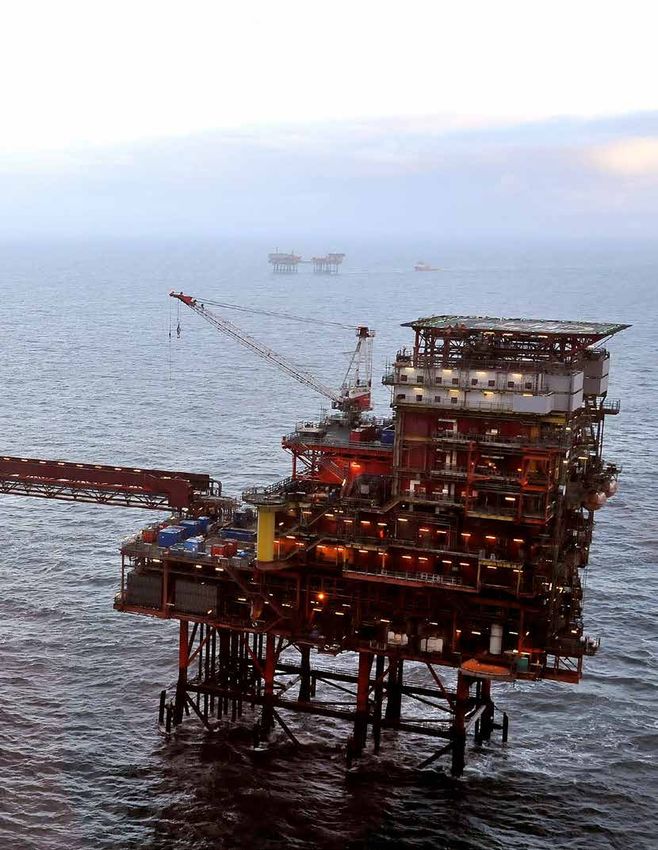
Version 3.0   Rough Gas Storage Facility                                                             02
—
20/07/2015

              Contents

              1. Introduction
              2.	The Rough gas storage facility
              3.	Licensed and technical
                  capacity of Rough
              4.	Rough operation
                  and maintenance
              5.	Alphabetical index of
                  technical terms

              © Centrica Storage Limited, 2014              Although every effort is made to
              This document and its contents are            ensure the correctness of information
              published in good faith by Centrica           submitted for publication, this document
              Storage Limited (“CSL”) for the benefit       may inadvertently contain technical
              of market participants, but remain the        inaccuracies or typographical errors.
              intellectual property of CSL. Other than      Moreover, operational parameters relating
              as published by CSL, they may not be          to the Rough facility may also change
              reproduced or distributed to any other        from time to time. CSL may therefore
              person or published, in whole or part,        make improvements and/or changes to
              anywhere. Neither CSL nor any of its          this information at any time without notice.
              affiliates, representatives or employees,     CSL assumes no responsibility for errors
              makes any representation or warranty,         or omissions in this publication or other
              express or implied, as to the fairness,       documents that are referenced by or
              accuracy or completeness of any of            linked to this publication
              the contents of this document, and nor
              will they have any liability relating to or
              resulting from their use.

              An Operational Overview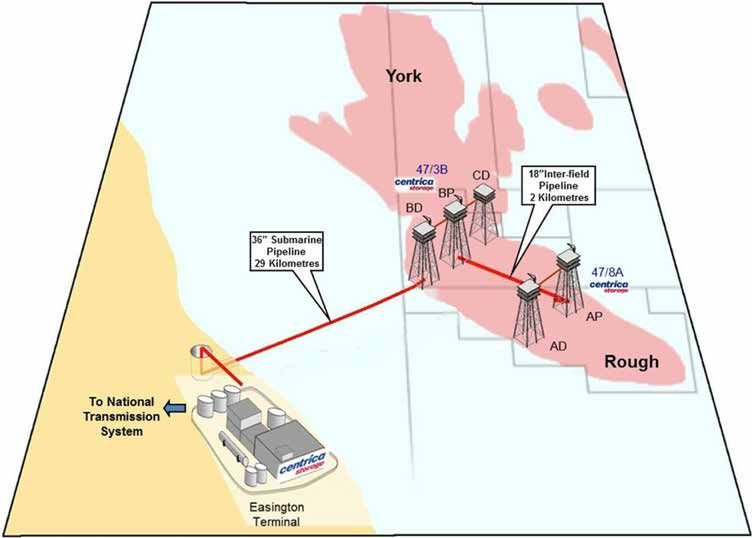
Version 3.0   Rough Gas Storage Facility               03

1
—
20/07/2015

              The Rough gas
              storage facility

              This guide explains the operational
              parameters of Rough and provides
              a brief explanation of the Rough gas
              storage facility, the licensed and
              technical capability and an outline of the
              operational and maintenance activity.
              Please note that in accordance with
              both the Gas Act 1986 (s.11C) and the
              Rough Undertakings, information about
              the day-to-day operations of Rough
              is likely to fall within the definition of
              ‘Commercially Sensitive Information’
              (CSI). CSL is under an obligation to
              disclose CSI on a non-discriminatory
              basis. Therefore CSL will be unable to
              answer any specific questions which
              could contain CSI unless the information
              is published to the whole market (e.g.
              within this Operational Guide or other
              form of market announcement, such
              as a REMIT notice).

              An Operational Overview
Version 3.0 Rough Gas Storage Facility 04
2
—
20/07/2015
The Rough gas
storage facility
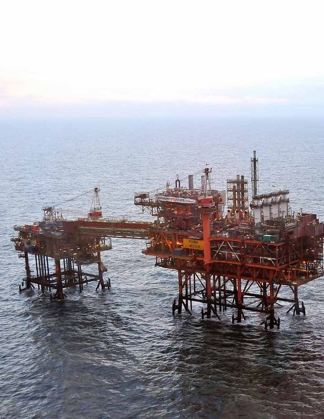
As shown in the schematic above, the 2.1.
Rough gas storage facility comprises: The Rough reservoir
The Rough reservoir is located approx.
• the Rough reservoir 29 km offshore from Easington and is
• offshore installations approximately 2.7 km below the sea bed.
(47/3B and 47/8A); and
2.2.
• the onshore terminal (Easington)
Offshore installations
The Rough reservoir is accessed
via two offshore installations.
An Operational OverviewVersion 3.0 Rough Gas Storage Facility 05
2
—
20/07/2015
The Rough gas
storage facility
2.2.1. 2.3.
47/3B Installation Easington Terminal
The 47/3B installation has up to 24 The Easington terminal is used for the
wells available for withdrawal or for injection and withdrawal of gas to and
injection. During withdrawal mode the from the Rough reservoir. The Easington
installation utilises the gas pressure terminal is also used for the processing
from within the reservoir to deliver and delivery of other gas (currently
gas to the onshore installation. from the Amethyst and York fields).
During gas injection the installation During gas withdrawal mode, the
utilises one or two compression units Easington terminal receives and
to raise the gas to the pressure of the processes gas and liquid from the
reservoir. The installation connects to 47/3B installation. The gas is dried,
the Easington terminal via a 36” diameter filtered, metered and delivered into the
subsea pipeline. National Grid Transmission system (NTS).
Liquids recovered from the process (gas
2.2.2. condensate and water) are processed,
47/8A Installation stored and then dispatched from the
The 47/8A installation has up to 5 wells site via either a dedicated pipeline (gas
available for withdrawal only and one condensate) or road tanker (water).
further well which is out of operation. The
installation connects to the 47/3B platform
via a 2km 18” diameter subsea pipeline.
As 47/8A is only used for production
operations, maintenance activities are
concentrated in the injection season.
An Operational OverviewVersion 3.0 Rough Gas Storage Facility 06
3
—
20/07/2015
Licensed and
technical capability
of Rough
The licensed and technical capability 3.1.
of Rough is outlined below and is Working volume (space)
described in terms of the working The gas within the Rough reservoir
volume (space), withdrawal capability comprises working gas, recoverable
and injection capability. gas and unrecoverable gas. Working
gas is made up of gas injected by CSL
customers from the NTS together with
CSL’s operational stock (refer to section
4.1 for definition of operational stock).
Recoverable and unrecoverable gas
constitutes Rough’s cushion gas and is
just under 320 bcf of gas. Under normal
operations, the cushion gas remains in
the reservoir and serves to maintain
the operating pressure required to
provide an effective storage service
from the Rough facility.
The Rough Working volume, together
with the recoverable and unrecoverable
cushion gas, is illustrated in the chart
below.
Chart 1:
Rough Working Volume Upper OGA Consent Rough Working
Volume
50 115 Maximum NRV Reached
100.6bcf on 02/11/2014
36.5TWh Max stock level range –
33.5TWh under REMIT 2015-33
30 47
NRV (bcf)
Stock (TWh)
15 -1
Minimum NRV Reached
0 -50 -31.2bcf on 12/04/2013
Lower OGA Consent
-216
Working Gas
Recoverable Gas
-368 Unrecoverable Gas Note: Oil & Gas
Authority (OGA)
formerly part of DECC
An Operational OverviewVersion 3.0 Rough Gas Storage Facility 07
3
—
20/07/2015
Licensed and
technical capability
of Rough
The Rough reservoir is subject to the The actual maximum NRV that Rough
provisions of a production licence, can achieve is dependent on a number
granted by DECC which states the of factors including: injection availability,
upper and lower reservoir limits to customer utilisation, system pressures and
which gas can be stored. carry-over of customer stock at the end of
the previous storage year. The maximum
The volume of Working gas that CSL NRV achieved to date is100.6 bcf on
is permitted to hold under its current 02/11/14.
consent from Oil and Gas Authority
(formerly part of DECC) is between a The actual minimum NRV that Rough can
maximum permitted Net Reservoir Volume achieve is also dependent on a number of
(NRV) of 115 bcf to a minimum permitted factors including: customer nominations,
NRV level of -50 bcf (i.e. 165bcf in total). any use by National Grid of the Operating
The -50 bcf NRV level is equivalent to the Margins gas it holds in Rough and the use
“zero” stock level (in kWh) as reported on of gas held by CSL for system integrity
the National Grid website after adjustment purposes. The minimum NRV achieved to
for any gas held by National Grid for date is -31.2 bcf on 12/04/13.
Operating Margins purposes.
Due to variations in calorific value
(approximately 39.2 MJ/m3), there are
in practice likely to be minor differences
between the -50 bcf NRV and the zero
stock level (in kWh).
An Operational OverviewVersion 3.0 Rough Gas Storage Facility 08
3
—
20/07/2015
Licensed and
technical capability
of Rough
3.2. The maximum technical capability
Withdrawal capability of Rough to withdraw is 485 GWhs/
Gas compression is not used for day (Withdrawal rate of 44.7mcm/day).
withdrawal from the Rough gas facility. The However, the 47/8A installation is unable
indicative withdrawal rate is a function of to withdraw at high reservoir levels due
total reservoir stock as shown in the Chart to the high reservoir pressure.
2. However, actual rates achieved are also
influenced by a number of factors including Withdrawal rates decline as the reservoir
ambient conditions, well performance empties due to the reducing pressure in
and the pressure of gas on the NTS in the the reservoir and the potential for sand
vicinity of Easington. The chart is accurate production.
to within a tolerance of 10%. The capability
curve assumes constant withdrawal
rates from the reservoir. Rates could be
increased at a given stock level if there
have been significant periods of relaxation.
An Operational OverviewVersion 3.0 Rough Gas Storage Facility 09
3
—
20/07/2015
Licensed and
technical capability
of Rough
In order to provide market participants with Short term reductions in the withdrawal
the most up-to-date information, CSL will capability will generally be announced
generally inform the market where Rough to the market on the CSL website as
capability in withdrawal mode deviates outlined in section 4.
or is expected to deviate from the line
shown below by 5mcm/d or more. CSL Total stock levels in the Rough reservoir are
will publish an updated version of this chart published on a daily basis on the National
here whenever the expected curve deviates Grid website (under Storage and LNG
by more than 5mcm/d from the previously Operator information) at: http://www2.
published version. CSL will publish both nationalgrid.com/uk/Industry-information/
the original and updated withdrawal gas-transmission-operational-data/
curves, normally by issuing a revised supplementary-reports/. The stock levels
version of this document on its website. reported on the website exclude any gas
The current version of Chart 2: Withdrawal held by National Grid for Operating Margins
curve (Maximum rate vs. Stock) dated purposes and the amount of stock held for
20/07/15 shows the withdrawal capability this purpose is currently 0.444 TWh.
for 2015/16.
Current version 20/07/2015 Chart 2:
Withdrawal Capability
50 Withdrawal
curve (Maximum
45
rate v Stock)
40
35
Max Rate (MSCM/d)
30
25
20
15
10
5
0
0 2 4 6 8 10 12 14 16 18 20 22 24 26 28 30 32 34 36 38 40 42 44
Stock (TWh)
An Operational OverviewVersion 3.0 Rough Gas Storage Facility 10
3
—
20/07/2015
Licensed and
technical capability
of Rough
3.3. Under two train operations, the maximum
Injection technical capability of Rough to inject
The maximum injection rate is a function is generally 305 GWhs/day (but this could
of reservoir pressure which can be be higher if additional NTS exit capacity
approximated by total reservoir stock is available at Easington). Injection rates
as shown in the Injection Capability decline as the reservoir fills due
graph. However, actual rates achieved to pressure increase in the reservoir.
are also influenced by a number of
factors including, historic injection rates, Once the reservoir reaches a critical
atmospheric temperature and pressure pressure level, it is only possible to inject
conditions, the calorific value of gas, the using a single train (compressor). By
pressure of gas on the NTS in the vicinity default, in the standard operating mode,
of Easington and well and compressor the move to single train operations is
performance (typical error is around expected to occur around a stock level
10%). Injection rates may be higher than of 34 TWh (assuming 100% injection
indicated if there is a period of reduced utilisation) to 38 TWh (assuming 50%
nominations allowing the reservoir to relax. injection utilisation). Under REMIT 2015-
33 operating mode, the move to single
Injection has three possible operation train operations is expected to occur
modes which are driven by the pressure around a stock level of 26 TWh to 28 TWh.
in the reservoir: Significant periods of relaxation (e.g. the
annual maintenance) in the reservoir
1. “Two train” where both compressors will also impact the stock level at which
on the 47/3B are in operation single train operation applies. CSL will
generally make a market announcement
2. “Single train” where one compressor
on the expected date of the switch to
on the 47/3B is in operation
single train operation.
3. “Stop/start” where one compressor
on the 47/3B is run for a period and
then the reservoir is allowed to relax
for a period (up to 48 hours depending
on fullness).
An Operational OverviewVersion 3.0 Rough Gas Storage Facility 11
3
—
20/07/2015
Licensed and
technical capability
of Rough
As the reservoir pressure rises further, at Performance during the injection season
a certain point in time CSL may need to will be reported via REMIT bulletins on the
operate injection on a non-continuous Centrica Storage website. The Injection
‘stop-start’ operation. By default, in the Capability graph, Chart 3: Injection
standard operating mode, the move to curve (Maximum rate vs. Stock), may be
stop/start operations is expected to occur updated during the injection season based
around stock levels above 37 TWh with upon actual reservoir performance.
the precise level dependent on reservoir
pressure. Under REMIT 2015-33 operating Short term reductions in the injection
mode, the move to stop/start operations capability will generally be announced
is expected to occur around stock levels to the market on the CSL website as
above 29 TWh. Typically, injection is run outlined in section 4 below.
on single train operation for 24 hours and Total stock levels in the Rough reservoir
then the reservoir is allowed to relax for 24 are published on a daily basis on the
hours with the relaxation time increasing National Grid website (under Storage
at higher reservoir pressures. The injection and LNG Operator information) at: http://
rates shown in the graph below show the www2.nationalgrid.com/uk/Industry-
average rate – actual rates will be around information/gas-transmission-operational-
10mcm/d during “start” and zero during data/supplementary-reports/. The stock
“stop”. CSL will generally make a market levels reported on the website exclude
announcement on the expected date of any gas held by National Grid for
the switch to “start/stop” operations. Operating Margins purposes and the
Recent investment in Rough means amount of stock held for this purpose
that injection can remain in continuous is currently 0.444 TWh.
single train operation for longer duration,
potentially until the end of the injection
season.
Current version 20/07/2015 Chart 3:
Injection Capability
35
Injection curve
(Maximum
30
rate v Stock)
25
(End of dual train)
Max Rate (MSCM)
20
Refer to REMIT 2015-33
15
(End of continuous
single train)
10
5
0
0 2 4 6 8 10 12 14 16 18 20 22 24 26 28 30 32 34 36 38 40 42 44
Stock (TWh)
An Operational OverviewVersion 3.0 Rough Gas Storage Facility 12
4
—
20/07/2015
Rough operation
and maintenance
Centrica Storage Ltd (CSL) aims 4.2.
to ensure that Rough is operated Essential maintenance requirements
safely, efficiently and to its maximum This maintenance is carried out to
capability with high levels of reliability. ensure that the Rough Storage facility
The operation of Rough is primarily continues to operate in a safe and efficient
driven by customer nominations, manner and delivers to the contractual
however, a range of factors including, requirements of our customers and in
essential maintenance of the facility, line with the expectations of the market.
network related factors (pressure, gas
quality) and market factors (economic CSL is committed to planning the timing
signals to use storage capacity) of these outages with regard to minimising
will all influence the operations of the impact upon the gas market.
Rough within and across years. At
The timing of the outages, however,
certain times, CSL may not flow in
cannot always be predicted or pre-
line with customer nominations as it
determined at the start of the gas year
is more efficient to not flow the gas or
and therefore timing and subsequent
turnaround the site (for example a small
announcement of an outage will be
injection or withdrawal nomination).
based upon a number of factors
4.1. including manufacturers’ maintenance
CSL operational stock recommendations, reservoir pressures,
CSL holds stock in the reservoir in line gas composition and usage of the
with CSL’s regulatory and contractual facilities by our customers.
obligations to ensure the integrity and
efficiency of the storage operation and
the operation of the Storage Service
Contract. Stock is used for the purposes
of fuel gas, to maintain steady flows,
to keep flows above sweep rates or
for pigging and for customer stock
management as a result of outages.
At certain times it will be necessary
for CSL to inject or withdraw gas to
manage the stock levels held by CSL
for these purposes.
An Operational OverviewVersion 3.0 Rough Gas Storage Facility 13
4
—
20/07/2015
Rough operation
and maintenance
4.2.1. The pigging operation should be carried
Withdrawal – keeping the out at a production rate of no more than
sealine free of liquids 10mcm/d, in order to maintain the pig at
It is periodically necessary to run a ‘pig’ a safe and prescribed speed throughout
through the 36” sealine. The pig pushes the run, and takes in the order of 6 hours
out any contaminants from the sealine to complete.
such as wax, liquids etc. that have settled
in the line, and reduces the risk of pipeline Compared to a maximum withdrawal rate
corrosion. A pig is simply a sphere whose of 44.7mcm/d, pig runs effectively reduce
size is that of the diameter of the sealine the maximum withdrawal capability to
and is inserted into the sealine from the around 10 mcm/d or approximately 25%
offshore platform and received at the once ramp rates (see below) are also
Easington terminal. taken in to account.
Pigging is more common at the end of the Once the pig run is completed the plant
withdrawal season, when the gas is wet can either be shut down, turned around
with liquids naturally contained within the to injection mode, or it can continue
reservoir, and when the gas flow cannot with gas production.
be maintained at a sufficient level in order In the event that net customer withdrawal
to sweep the liquids through the sealine. nominations are insufficient for this
A minimum production rate of 22.7mcm/d purpose, CSL may utilise some of
(known as sweep rate) is required for a the operational stock it holds in the
continuous period of 18 hours in order reservoir in order to run the pig or
to remove liquids from the sealine and maintain sweep rate.
negate the need to run a pig. If the sweep
rate cannot be maintained then the sealine
must be pigged within 44 hours in order to
prevent liquids building up.
An Operational OverviewVersion 3.0 Rough Gas Storage Facility 14
4
—
20/07/2015
Rough operation
and maintenance
4.2.2. 4.2.4.
Withdrawal – sales gas filter changes Injection – gas compression
Before gas enters the NTS, gas is passed Gas compression is always required
through two parallel sales gas filters. The when gas is being injected back into
filters are essential to maintain critical the reservoir. There is one compression
metering equipment just prior to the gas unit at the Easington Terminal and
entering the National Gas Transmission two compression units on the 47/3B
system. The filtering elements housed installation. Depending upon the required
within the onshore sales gas filters need injection flow, one or both of these
to be changed out for clean filtering compressors are required to provide the
elements. The differential pressure across second stage of the gas compression,
the filters is monitored and when trigger raising the gas pressure to the reservoir
points measuring the effectiveness of pressure. Compressor maintenance is
the filter process are neared, outages are planned in advance when the associated
planned to facilitate the change. Each outage is expected to have minimal
of the two filter housings requires a 50% impact upon the customer.
outage for a 12 hour period, meaning that
production rates are restricted to 50% 4.2.5.
of maximum, circa 22 mcm/d rate. Gas generator (compressor) washes
For optimal operation, the gas
Assuming that both filters are changed compressors should be subject to a water
within one day, and compared to a wash approximately every 750 hours of
maximum withdrawal rate of 44.7mcm/d, operation. A compressor wash takes in
changing both gas sales filters reduces the order of 4 hours to complete. Where
the maximum withdrawal capability over a compressor wash is required Centrica
a full day by around 22 mcm/d or 50%. Storage will inform the market of the
date, timing and operational impact.
4.2.3.
Withdrawal – ramp rates
When gas production (withdrawal)
commences, after shutdown or in
transition from injection mode the rate
of withdrawal needs to be “ramped”
gradually in order to ensure safe and
reliable plant operation.
The ramp rate is 10.4 million cubic metres
per day rate per hour, meaning that it will
take four hours to increase the rate from
zero to maximum withdrawal capability
(44.7mcm/d).
An Operational OverviewVersion 3.0 Rough Gas Storage Facility 15
4
—
20/07/2015
Rough operation
and maintenance
4.2.6. 4.3.
Other Maintenance Activities Operational Turn Around Times
Wherever possible, any maintenance When there is a change in gas nomination
work that requires the widespread resulting in the need to ‘turn around’
isolation of gas to make the work area the operation from one mode (injection/
safe is scheduled to take place in the withdrawal) to the other, a minimum of
Annual Maintenance Shutdown, normally at least 4-6 hours is required to safely
planned for September. These planned shut down one mode and to reconfigure
shutdown windows typically last for 14 to the plant to the opposite mode. During
21 days. However, there is a limit to the this period no gas can be injected or
amount of activity that can be fitted into withdrawn from the facility.
these shutdown windows.
The sealine will require pigging when
Where additional maintenance outages are changing mode from withdrawal
required, every effort is made to ensure to injection, and taking the pig run
that any other outages are scheduled to into account, the turnaround time is
take place at a time when the impact upon extended to between 6–10 hours.
customers and the market is minimised.
In many cases the equipment being taken 4.4.
out of service for maintenance does not Contacts at CSL
affect the availability of the operation If you have any questions about the
directly, but the isolation required to operation of the Rough Storage facility
provide safe access to the equipment please email Commercial Operations at
may. Centrica Storage is committed to Opsdesk@centrica-sl.co.uk
the safety of its employees and protection
If you would like to find out more about
of the environment and to the requirement the products and services that we offer
to meet stringent isolation standards then please email Sales & Marketing at
aligned to procedures which are written to Salesandmarketing@centrica-sl.co.uk
provide compliance with HSE standards
and guidance.
An Operational OverviewVersion 3.0 Rough Gas Storage Facility 16
5
—
20/07/2015
Alphabetical index
of technical terms
Please ‘control
click’ on the term/ Easington Terminal
hyperlink of interest,
below, in order to be Gas Compression
taken direct to the
relevant section of the
operational guide.
Gas Generator (Compressor) Washes
Gas Production Ramp Rates
Injection
47/3B Installation
47/8A Installation
Operational Turn-Around Times
Other Maintenance Activities
Pigging
Sales Gas Filter Changes
“Single Train” operations
“Stop/start” operations
Sweep rate
“Two train” operations
Withdrawal
Working volume
An Operational OverviewRough Gas Storage Facility — An Operational Overview
You can also read


