Sample Micro Hydro
   Initial Report
←
→
Page content transcription
If your browser does not render page correctly, please read the page content below
Sample Micro Hydro Initial Report
Sample Micro Hydro Initial Report

Introduction

The Hydro Burn at Glen Water was visited by Richard Haworth of Glen Hydro to assess
its suitability for a micro hydro installation. It is the aim of this report to help the owner
decide whether to invest in a full feasibility study.

The Hydro Burn has an unusual catchment area, as it extends over three kilometres in a
narrow valley. This is not a particularly large catchment area but the west coast of
Scotland does benefit from high rainfall levels. From the catchment valley, the burn
runs north westward steeply down the hillside to Loch Seaside. Access is provided by a
track which crosses the burn by a wooden bridge at grid reference NR 7369 5223. A few
metres downstream the burn is also crossed by an 11kV distribution power line.
Approximately 100m further downstream, the burn crosses the march onto a
neighbouring estate.

The power produced by any hydroelectric scheme is a product of both the flow and the
height loss (head) between the intake and turbine. On the Hydro Burn, the head
relevant to this potential scheme is developed over a relatively short distance as the
burn descends the steep hillside. This is significant, as a short penstock length reduces
the capital costs and increases the viability of the scheme. A steeper section of burn
also has favourable influence on the application for an abstraction licence from SEPA
(see below).

There are lengths of the banks of the burn which are not in the ownership of the Estate
(see Appendix 1, showing the estate boundaries). This should be addressed prior to any
application for licences/planning.

                                          Page 1 of 10
Catchment area and flow levels
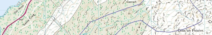
The catchment area of the proposed scheme measures 1.08 km2 and is shown in the
map extract below.
Hydro Burn catchment area
As would be expected, average rainfall levels in the area at 1300-1700 mm/year are
reasonable, being in line with the Scottish average (1436mm) and significantly above UK
average (1079mm).
Predictions of the flows in the burn have been made using LowFlows, a software
package widely used throughout the industry, including by SEPA. LowFlows calculates
predicted flow levels based on historic rainfall levels and data on the local
geology/geography which influences the amount of rainfall that runs off into
watercourses.
LowFlows analysis gives the following data for the catchment area outlined above:
Basin area 1.08
Annual average runoff (mm) 1509
Base flow index 0.16
Mean annual flow (l/s) 52
Qn90 flow (l/s) 5
Qn95 flow (l/s) 3
Page 2 of 10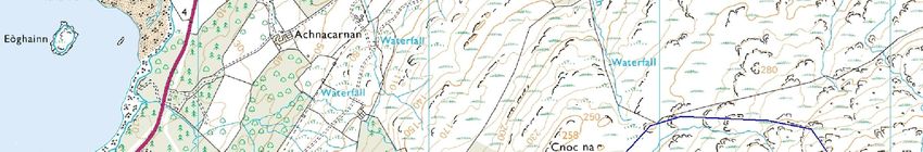
The runoff figure is the annual amount of rainfall flowing out of the catchment as
surface water and is a factor of rainfall levels and the effect the local terrain & geology
has on water retention/dispersal. It is useful as a relative measure of flow for different
sized catchment areas. The predictions in excess of 1500mm are significantly above
both the Scottish (1049mm) and UK (645mm) averages.

The base flow indexes are an indication of how quickly the rainfall would flow in to the
burns and is based on the local geology. Potential values range from 0.1 to 1.0 with
lower values representing catchments that are ‘flashy’, i.e. rainfall will run off very
quickly. The low base flow index indicates that water levels will fluctuate very quickly.
Whilst this will give rise to some very high spate flows of water, it is not beneficial to a
hydro scheme as the system will need to be sized on the longer term flow of water and
will not be able to make additional utilisation of very high flow levels.

LowFlows also predicts the flow levels across the year and these are expressed as
exceedence percentiles. The Qn90 figure shown above is the flow level that is exceeded
90% of the year, i.e. for 90% of the year the flow is above 5 l/s. Qn95 is the flow
exceeded 95% of the year. These figures are important as they are commonly used by
SEPA to set the level of compensation flow. This is the flow which must be left in the
river at all times (subject to sufficient natural flow) and cannot be abstracted for
generation purposes. In the case of Hydro Burn it is expected that SEPA would require
the higher Qn90 figure as the compensation flow since the catchment area is under 10
km2.

The performance of hydro schemes is impossible to predict with certainty due to
variations in rainfall levels and therefore watercourse flows. These figures are based on
a widely utilised method of predicting flow levels but are given as guidance only and
should not be considered as a guarantee. Further flow analysis to validate these figures
would be undertaken during the ensuing stages of the project.

Scheme design overview

Over much of its length the burn has eroded a deep gorge in which it now runs. These
gorges prevent the use of large sections of the burn for the construction of both the
intake structure and the outfall from a turbine house. The cost effectiveness of any
hydro scheme has a close correlation to the steepness on the section of watercourse
involved. Therefore the steeper section of the burn upstream from the access track
bridge is favoured for the proposed scheme. It would be normal to site the turbine
house as low as possible on the burn, while within the boundary of the property.
However, below this section, the burn below the bridge quickly enters a narrow gorge,

                                          Page 3 of 10
around 10 metres deep, which would make the construction of a turbine house on this
stretch very difficult and costly.
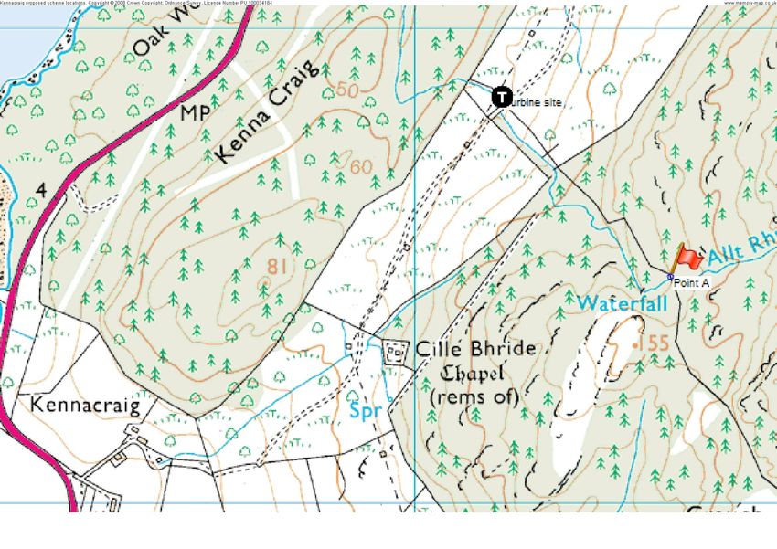
Glen Water proposed scheme, location of turbine house and intake
Above the bridge, the hillside soon starts to rise steeply towards the wooded section
above. Once the steeper gradient is reached, the burn again runs in the bottom of a
deep gorge. This section of the watercourse is currently on land belonging to a
neighbouring estate.
Approximately 500m upstream of the bridge, there is a large waterfall (marked on the
1:25000 OS map). 60m upstream of this waterfall, the burn re-joins the client’s march,
with its northern bank being part of the Glen Water Estate (point A on the map above).
Above this point the gradient of the burn becomes markedly reduced, meaning that it
would not be cost effective to take the site of the intake much farther upstream.
The geological features of this small area of land mean that there are two possible sites
for an intake structure. The lower of these is just above the large waterfall and
downstream of point A. From here the penstock would run down through the conifer
forest requiring a significant amount of deforestation. The second, higher, option for an
intake would be around 40 meters upstream of point A. An intake located here would
enable the penstock to be run down the northern side of the forest. With either intake,
Page 4 of 10
elements of the scheme would involve land owned by the neighbouring estate and a
suitable agreement should be reached with them prior to any development.

The intake design would consist of a concrete weir constructed in the burn bed and
include a screen to filter out debris in the water (which can damage some types of
turbine if not removed). This screen would be a Coanda type which achieves a high
degree of filtration and minimises maintenance. The intake structure would also include
a large settling tank, which would allow any air introduced by the Coanda screen to be
removed from the water prior to it being introduced to the penstock.

The proposed pipeline route is on the north bank of the burn. The penstock pipe would
need to be buried beneath ground to comply with planning requirements and to provide
support and protection for the pipe. Site access would be gained from a temporary
track formed close to the march fence on the north side of the burn. The total penstock
length would be around 500 meters.

The proposed turbine house would be sited close to the burn in the area immediately up
or downstream from the wooden bridge. The exact location would need to be
determined taking into consideration the maximum flood level of the burn. Connection
to the 11kV line would be relatively straightforward.

The gross head (height difference between intake and turbine) of the scheme is 60m if
the lower of the two possible intake sites is used, or 64m for the upper intake. There
are many varying types of turbine capable of generating hydro power and the type of
turbine selected depends on both the head and flow of the system. This site would suit
a Pelton wheel turbine, which is ideally suited to sites of low flow and high head.

Electricity generated by the system can either be connected direct to the grid for export
or via a property where it may be utilised to offset current electricity purchased (with
any excess being exported). The latter has financial benefits in that the cost of the
electricity saved is far in excess of that paid for exported electricity. However, to run a
cable to the Glen Water buildings would require a cable over a kilometre long. This
would result in a considerable voltage drop, which in turn would necessitate a large
cross sectional area of copper in the cable to minimise the drop. Therefore this solution
would be prohibitively expensive and far outweigh any benefits from offsetting current
electricity cost. Therefore direct connection to the grid is proposed.

                                         Page 5 of 10
Scheme power generation
Gross head (m) 60
Estimated net head (m) 52
Turbine rated flow (l/s) 46
Turbine capacity (kW) 15
Capacity factor 49.97%
Annual power generation (MWh) 65.7
The net head available for generation is lower that the gross head (or actual height
difference in water levels) due to the falls required in the system design to allow flow of
water and pressure losses in the pipe.
The capacity factor is the actual generated power expressed as a percentage of the
power that would be generated if the turbine were running at full power throughout the
year. Obviously there are times when the water flow levels are not sufficient to run the
turbine at full power and indeed some periods when generation will stop completely.
Should the higher intake be utilised, the head will be marginally greater. It is likely that
the turbine would still be rated at 15 kW as this is a step in the level of FITs payments
(see below). However the rated flow would decrease slightly and the capacity factor
improve leading to a slight overall increase in the power generated. This would in turn
improve the income and return figures later in this report. We have opted to present
the (slightly) more pessimistic option subject to further detailed design.
Environmental and planning considerations
Any hydro scheme requires an abstraction licence from SEPA. In general SEPA are less
favourable to schemes under 100 kW and have issued guidance outlining the factors to
be considered. Key within these is the steepness or slope of the watercourse and the
length affected. Steeper watercourses are more favoured with a gradient of 1 in 10 or
10% being a critical threshold with the guidance. The average slope of the section of the
Hydro Burn under consideration is very close to 10% (taking the height loss over the
length of the course of the burn). This will need to be validated by detailed survey, but
it is hoped that the Hydro Burn is unlikely to be considered by SEPA as a significant fish
Page 6 of 10habitat and a scheme could be considered favourably for an abstraction licence. The
end decision is a result of consultation with the local SEPA officials and our experience is
that their approach can vary significantly between different SEPA offices. Were the
client to choose to proceed with the scheme, we would recommend early consultation
with SEPA.
Planning permission is likely to be required, particularly for the turbine house or shelter
and this will probably require a design that is sympathetic with the surrounding
environment.
Revenue generation
The new government feed in tariffs (FITs) guarantee a revenue for each kWh of
electricity generated regardless of whether it is used locally or exported to the grid. The
feed in tariff is guaranteed for twenty years from the start date and will increase at the
rate of inflation (RPI). The tariff rate declines with higher levels of generation as
detailed in the table below. This is reflective of the reduced capital costs per kW of
larger schemes.
Generation capacity Revenue p/kW h
≤15 kW 20.9
>15 - 100kW 18.7
>100kW - 2MW 11.5
>2MW - 5MW 4.7
Tariff levels April 2011 – March 2012
It will be noted that the scheme (utilising either intake) would be sized at 15 kW to
maximise the FITS rate per kW h. Though not applicable in the proposed scheme, where
the generated electricity is used to replace power previously purchased there is a saving
of approximately 12p per kWh. Electricity exported to the grid is guaranteed a revenue
at a minimum of 3p per kWh and may be higher if market conditions dictate.
The revenue generation figures below presume that the system would be connected to
the grid at the turbine house and that there would be no savings on current electricity
bills. Should the higher intake be used, revenues would be approximately 2.5% higher.
Page 7 of 10Annual power generation (MWh) 65.7
Feed in tariff £13,724
Saving on current electricity bills n/a
Exported electricity £1,970
Gross revenue £15,694
Capital costs
The terrain on which the penstock would be installed is rugged and contains an
unknown amount of rock. Some form of access track would have to be constructed over
this terrain to allow the necessary machinery access for the construction of the intake
and burying of the penstock pipe. These aspects of the scheme are harder to estimate
without visiting the site with a contractor or a construction consultant, which would be
done at the feasibility study stage of the project development.
It is nevertheless estimated that the scheme would cost in the region of £154,000. This
cost is based on the construction of a scheme designed and built to current industry
best practices. Such a scheme, well maintained, should have a life expectancy well in
excess of 25 years.
It should be understood that this is very much an initial estimate based on our
experience with other schemes. A significant amount of detailed site analysis,
engineering calculations and obtaining of quotes would need to be done during the next
feasibility stage to generate more accurate budget figures. At this stage we would also
get more accurate figures for the cost of grid connection to the 11kV lines, which would
be done be SSE, the Distribution Network Operator (DNO).
These costs do not take in to account any payments, either one off or ongoing to the
landowner of the adjoining estate.
Page 8 of 10Scheme returns
The FITs payments which make up the majority of the income are guaranteed by the
government for 20 years. However, the expected lifespan of a hydro scheme should be
in the region of 25 years and the scheme could go on for double this if properly
maintained. An allowance should be made for running costs and some capital
replacement in the longer term. This is expected to average £1,000 over the 20 year
period, although expenditure in the early years would be expected to be much lower.
This could be reduced if elements of the routine maintenance could be undertaken ‘in
house’.
Based on the figures above the predicted returns for the schemes would be as below.
Gross revenue £15,694
Annual costs £1,000
Net revenue £14,694
Capital cost £154,000
Rate of return* 9.54%
Payback period (years)* 10.48
*Undiscounted for future years as FITs increases by RPI.
Conclusion and the way forward
Hydro Burn has good potential for hydro power generation. The access problems for the
construction of the intake structure and the penstock mean that the construction costs
are relatively high, despite the short penstock length. The return on the capital
invested, at 9.54%, is good and above the government target of 8% targeted in setting
the feed in tariffs.
Should you wish to advance, we would recommend that before any further work is done
on the development of the schemes, discussions are held with the neighbouring
landowner in relation to the location of the scheme. Should those prove positive we
would then recommend commissioning a full feasibility study to develop the project in
detail.
Page 9 of 10The feasibility study which would include the following steps:
• Detailed design & method statement
• Contractor and equipment estimates/quotes
• Detailed capital cost breakdown
• Consultation with the SEPA to initiate the approvals process, identify areas of
concern and potential solutions
• Seasonal flow/power/revenue model
• In river flow spot monitoring
• Grid connection costing and consultation with the DNO
Completion of the feasibility report would allow you to decide whether to proceed to
apply for an abstraction licence and planning permission. Our charge for the full
feasibility study is £xxxx (inclusive of all expenses) ex VAT. Charges for later stages of
the project (as detailed at the end of this report) would be identified during the
feasibility stage.
We trust this report is helpful. Please do not hesitate to contact me if you have any
queries or would like to discuss this report further.
Richard Haworth
Glen Hydro
Email: richard@glenhydro.co.uk
Office: 01250 881732
Mobile: 07971 577320
Page 10 of 10You can also read