SavariaTM rear entry Wheelchair Accessible Vehicle - Owner's Manual
←
→
Page content transcription
If your browser does not render page correctly, please read the page content below

Savaria      rear
            TM
                     entry
 Wheelchair Accessible Vehicle

        Owner’s Manual
                                 1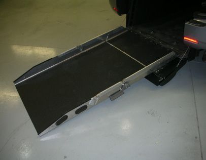
table of contents

    1   Introduction

    2   Ramp Operation
        2.1 Deploying Ramp
        2.2 Stowing the Ramp
        2.3 Flat-Floor Ramp

    3   Securement of Wheelchair
        3.1 Boarding the Wheelchair Passenger
        3.2 Securing the Wheelchair
        3.3 Occupant Restraint System
        3.4 Electric Retractors

    4 Vehicle Seating
      4.1 Dodge Grand Caravan
    		    4.1.1 2nd Row Fixed Bucket Seats
    		    4.1.2 2nd Row Flip Bucket Seats
    		    4.1.3 2nd Row Flip-Assisted Bench Seat
    		    4.1.4 2nd Row Removable Bench Seat
    		    4.1.5 3rd Row Flip Bench Seat
    		    4.1.6 2nd Row Footplate/Storage Bin
      4.2 Toyota Sienna
    		    4.2.1 3rd Row Flip Bench Seat

    5   Emergency and Maintenance
        5.1 Spare Tire Removal
        5.2 Routine Maintenance
        5.3 Towing

2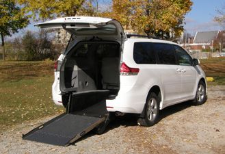
section 1

Congratulations on the purchase of your SavariaTM rear entry wheelchair
accessible vehicle! Savaria has developed this conversion with your
safety and satisfaction in mind. This owner’s manual will assist you in
operating your converted vehicle safely.

Please be sure to read this manual thoroughly before operating your
Savaria accessible vehicle. Ensure that you are familiar with all controls
and understand how to properly use the supplied equipment.
Your Savaria accessible vehicle is a quality product designed to provide
many years of dependable service when properly operated and
maintained. Improper use or abuse of the conversion may cause severe
injury or death.

It is important that any replacement parts used are authorized by
Savaria. Do not attempt to modify, change, replace, remove or alter the
conversion in any way, as this may render the vehicle unsafe and void
any replacement warranties. Always ensure that anyone operating this
accessible vehicle is fully capable and has a thorough understanding of
all aspects of the vehicle, ramp and tie-down system. Anyone using the
conversion must understand the information in this manual.

Safe operation of the vehicle requires complete and unimpaired
attention at all times. As with all motor vehicles, do not attempt to
operate this vehicle during or after consumption of medication, drugs
or alcohol.

For information that is not addressed in this manual, please refer to your
factory Owner’s Manual. Thank you for giving Savaria the opportunity to
help you achieve better mobility for life!

                                                                             3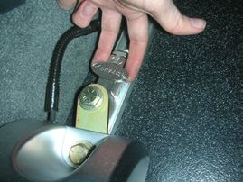
section 2

    Ramp Operation
    2.1 Deploying the Ramp

     1. Ensure your vehicle is on level ground, the transmission is in park
        and the ignition is off. Open the rear liftgate.

     2. Place one hand at the top of the ramp and push inward, while
        using your other hand to turn the latch release handle in the
        clockwise direction to disengage the ramp latches.

     3. Using either of the handles located at the sides of the ramp,
        carefully pull the ramp out. Unfold the ramp as you continue to
        lower it to the ground.

    1                                      2

    3                                      4
4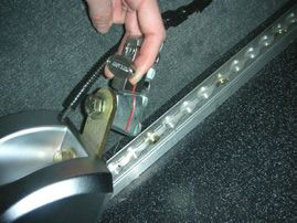
2.2 Stowing the Ramp

 1. Ensure ramp and hinge points are clear of debris.

 2. Using the handles located at the sides of the ramp, carefully lift the
    ramp.

 3. Guide the ramp to its folded position by rotating the smaller panel
    so that it is flat against the larger panel. A magnet will hold the
    ramp in this position.

 4. Firmly push the ramp towards the vehicle until it is in the latched
    position. Keep hands in the anti-slip area to avoid potential
    injuries. If the ramp is not completely latched, rotate the ramp
    latch release handle clockwise to release the ramp, and push the
    ramp towards the vehicle with more force. Repeat as necessary. If
    difficulties arise, please contact SavariaTM Vehicle Group for further
    assistance.

                                                                             5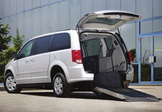
2.3 Flat-Floor Ramp (if equipped)

    If your accessible vehicle is equipped with a Flat-Floor ramp, you are
    able to create an entirely flat floor in the cargo area. The Flat-Floor
    Ramp has three panels separated by hinges; the main panel, the mid
    panel, and the end panel. The locations of the three panels are shown
    below.

                                               main panel

                                   mid panel

                     end panel

    Deploying the Flat-Floor:
     1. Ensure that the ramp is in the closed and locked position (please
        refer to section 2.2 for instructions).

6
2. Release the locking handles at the sides of the ramp by rotating
   them outward as shown. Be sure to hold the top of the ramp
   steady while doing this, so the mid-panel does not fall forward.

3. Rotate the mid-panel down, and then flip the locking handles back
   down out of the way.

4. Use the cut-out handles located on the side barriers of the end-
   panel to fold the end-panel out to create a fully flat floor.

1                                      2

3                                      4

                                                                       7
Stowing the Flat-Floor:
      1. Carefully reach into the vehicle and use the cut-out handles to pull
         the end-panel back, and lay it flat on the mid-panel.

     2. Rotate the locking handles, located on the sides of the ramp, to sit
        vertical against the backstop.

     3. Use the cut-out handles to firmly pull the mid panel to the vertical
        position. The locking handles will hook onto the ramp to hold it
        temporarily in the stowed position. While holding the top of the
        ramp and pulling it outward, re-engage the locking handles by
        rotating them upward to be parallel with the sides of the ramp.

        1                                    2
                                           Always hold the top of the ramp while
                                           operating the locking handles. Failure to do
                                           this may lead to the ramp falling forward.

                                           Do not use the Flat-Floor ramp or operate the
                                           Flat-Floor ramp handle mechanism when
                                           there is a wheelchair occupant inside the
                                           vehicle.

        3
8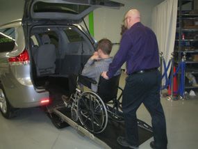
section 3

Securement of Wheelchair in Vehicle
3.1 Boarding a Wheelchair Passenger

 1. Deploy the ramp (please refer to Section 2 for instructions).

 2. Guide the wheelchair passenger up the ramp and into the vehicle.
    Wheelchair occupants must not attempt to enter or exit the vehicle
    unassisted.

 3. Ensure the wheelchair passenger is seated in a forward-facing
    direction, in the centre of the vehicle.

 4. Once the wheelchair passenger has been safely positioned, lock
    the wheelchair in place by applying the wheelchair brakes.

   Maximum allowable weight on ramp is 1000 lbs.

   Never attempt to enter the vehicle in a wheelchair unless being assisted by someone who is
   capable of guiding the wheelchair up the ramp and into position for safe transportation.

                                                                                                9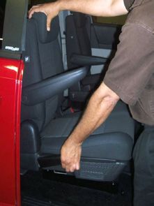
3.2 Securing the Wheelchair

     1. Locate the wheelchair in the van to optimize the wheelchair user’s
        comfort while keeping the retractor webbing and seatbelts within
        the safe operating angles. Utilize the alternative rear Slide ‘N Click
        tie down locations and the forward track to achieve this goal. See
        the picture below illustrating the safe webbing angles, or refer to
        the Q’Straint user guide.

                     WHEELCHAIR REFERENCE PLANE                 WHEELCHAIR REFERENCE PLANE

                                             REAR                     FRONT
                                      SECUREMENT                      SECUREMENT
                                           POINTS                     POINTS

                                         30˚                            40˚

                                45˚                                           60˚

                 0                                                                            0
       10˚                10˚                                                       25˚                25˚
                                                    SIDE VIEW
             REAR VIEW                                                                    FRONT VIEW
                                 Preferred angles and location of tiedown
                                 straps from wheelchair securement points to
                                 vehicle anchor points. Angle front tie downs
                                 out for lateral stability when possible.
                                 D=12˚ (300 mm)

       Failure to maintain the angles shown in the above diagram will prevent the restraints from
       functioning as intended, which could result in serious injury during a vehicle collision.

10
2. Fasten the front retractors to the tracks (L-track rails in the Caravan,
and L-track oval pockets in the Sienna) located on either side of
the floor as shown in the image below. To attach a retractor to the
track, push down and slide the retractor fitting along the track until
the spring-loaded plunger is locked in place. For the Caravan (1),
both left and right retractors should be located the same distance
from the front of the lowered floor. For the Sienna (2), both front
retractors should be located the same distance from the sides of
the lowered floor.
1 2
Pull firmly on the fitting to ensure that the plunger is properly
seated and locked in the track.
11To remove the front retractor, lift the lock plunger and slide the
fitting in either direction along the track while lifting the assembly
out of the track.
3. Once the retractors have been fastened to the track, attach the
J-hook on the retractor webbing to the front of the wheelchair
frame. The front securement point should be positioned as
high as possible on the wheelchair frame for maximum safety as
recommended by the wheelchair manufacturer. Refer to your
Q’Straint Instruction Guide for ideal fastening geometry.
Refer to your wheelchair manual for instructions on selecting the most appropriate
wheelchair securing locations.
124. Allow the retractor to spool in and remove excess slack in the tie
down once the J-hook has been attached. Two front retractors are
required per wheelchair.
5. Attach the Q’Straint rear Slide ‘n Click retractors by sliding the
anchor of the retractor over the appropriate disk on the floor until
it clicks in place. Rotate the assembly until it faces the front of the
vehicle.
To remove the rear retractor, lift the lock plunger at the back of the
retractor and slide the assembly rearward off of the disk in the floor
as shown below.
136. The rear of the wheelchair may now be secured to the rear
retractors. Attach the J-hooks to the rear of the wheelchair frame
in the locations outlined in your wheelchair manual. Refer to the
Q’Straint Instruction Guide for ideal fastening geometry. Allow
the retractor to spool in and remove excess slack in the tie-down
once the J-hook has been attached. The tie down can be tightened
further by rocking the wheelchair back and forth or by turning the
knob on the side of the retractor. Two rear retractors are required
per wheelchair.
Refer to your wheelchair manual for instructions on selecting the most appropriate
wheelchair securing locations.
Be careful to keep straps away from sharp edges or corners.
All Q’Straint automatic retractors have a red tab located at the rear of
the unit. This tab is used to release the locking mechanism within the
retractor allowing the user to either extend the tie down or release the
wheelchair from its restrained position.
14Where attachment to the wheelchair is not possible with the J-hooks,
the use of an optional webbing loop is acceptable if affixed by either
method to the wheelchair as shown in the diagram.
or
It is recommended that the front retractors are stored on the L-track rails
or oval pockets, and the rear retractors are anchored to the Slide ’N Click
fittings when not in use.
It is not recommended to store retractors in the rear storage bin or the spare tire
cover pocket.
153.3 Occupant Restraint System
1. The supplied Q’Straint occupant restraint system is made up
of three parts: a lap belt, a belt buckle and a shoulder belt. The
system should only be used on the vehicle with which it was
supplied, and only as a complete unit. The system is not deemed
safe for use if any one or more parts are not available, or are not
used correctly.
2. The D-rings on the lap and buckle belts attach to the anchor pin
located on the top of each rear retractor. Attach these D-rings as
illustrated in the image below. The lap belt section attaches to the
driver’s side rear retractor, and the buckle section attaches to the
passenger’s side rear retractor.
lap belt
shoulder belt belt buckle
lap belt
belt buckle
1 2
3. Pass the free ends of the belt buckle and the lap belt through the
right and left sides of the wheelchair, where they will be positioned
as low as possible across the pelvis of the wheelchair occupant.
164. Attach the shoulder belt anchor pin to the D-ring connection at the
rear roofline of the vehicle.
5. Pass the free end of the shoulder belt over the passenger’s left
shoulder. Connect the belts together using the D-ring end of the
shoulder belt and the anchor pin on the lap belt. Clip the lap belt
assembly to the belt buckle at the passenger’s right hip. Remove
slack from the belts and ensure the occupant is comfortable.
When the occupant restraints are not in use, the spare tire cover pocket
and/or the rear storage bin provides a convenient storage area.
173.4 Electric Retractors
Refer to www.savaria.com/video/retractors for an instructional video on the
procedure and tips for safely securing the wheelchair in your vehicle using
electric retractors.
Boarding the Wheelchair Passenger:
1. Secure the front retractors. Ensure that they are located the same
distance from the front of the lowered floor. The front electric
retractors can be locked into the most forward position on the
L-track, approximately 30 inches from the front as provided by the
length of the electric cable. Choose the optimum position for the
electric retractors based on the intended position of the wheelchair
occupant and the Q’Straint user guide.
2. Guide the wheelchair occupant to the base of the ramp and lock
the wheelchair.
3. Press the red “unlock” button on the black control box located on
the passenger side at the rear of the vehicle.
4. Hook both front retractors to the wheelchair frame.
185. Press the black “lock” button on the black control box.
lock
unlock
6. Unlock the wheelchair and guide the wheelchair occupant into the
van, pulling back as you go to take up slack as the webbing spools
in the retractor. Failure to tighten the webbing in this manner may
result in the wheelchair user rolling back a few inches when the
vehicle is in motion.
7. When the wheelchair passenger is in the desired location, lock the
wheelchair.
8. Secure the Q’Straint Slide ‘N Click rear retractors to the discs fixed to
the floor (please refer to section 3.2.4 for instructions).
9. Connect the Occupant Restraint System (please refer to section 3.3
for instructions).
19Deboarding the Wheelchair Passenger:
1. Disconnect the Occupant Restraint System.
2. Remove the rear retractors. Don’t forget to press the red release
button on the rear retractor to release the lock and provide slack in
the webbing.
3. Press the red “unlock” button on the black control box.
4. Unlock the wheelchair and push it slightly forward to release
tension in the webbing.
5. Guide the wheelchair passenger out of the van and down the ramp.
6. Lock the wheelchair.
7. Remove the webbing hooks from the front of the wheelchair frame
and reattach them to the D-rings on the rear panels.
20section 4
Vehicle Seating
4.1 Dodge Grand Caravan
2nd and 3rd Row Seating Configuration Passenger Total Cap Max.
Description (Passengers Remaining
2nd Row 3rd Row + Cargo) Cargo Cap*
Bench Savaria 524 kg 42 kg
Original bench (1155 lb) (91 lb)
Equipment 2 person
7 0
Bench Savaria 524 kg 111 kg
Original stowed (1155 lb) (243 lb)
Equipment bench
5 1
Bench -- 559 kg 146 kg
Original (1231 lb) (319 lb)
Equipment
5 1
Buckets Savaria 556 kg 142 kg
Original bench (1225 lb) (313 lb)
Equipment 2 person
6 0
Buckets Stowed 556 kg 211 kg
Original bench (1225 lb) (465 lb)
Equipment
4 1
Stowed Stowed 556 kg 280 kg
Buckets bench (1225 lb) (617 lb)
Original
Equipment 2 2
Buckets -- 631 kg 286 kg
Original (1389 lb) (629 lb)
Equipment
4 1
Stowed -- 631 kg 355 kg
Buckets (1389 lb) (781 lb)
Original
Equipment 2 2
21* Calculation in previous table assumes all usable seats are occupied and each passenger weighs 150 lbs.
Passenger weight does not include weight of wheelchair; wheelchair weight must be included as cargo.
Be cautious when lifting seats. Never attempt to lift a bench unless there are at least two
people involved who are capable of heavy lifting. Always use proper lifting techniques to
avoid injury
Lowering the Bucket Seat Backrest & Headrest:
1. Pull the lever on the outboard side of the bucket seat while holding
the backrest.
2. Gently lower the backrest while standing clear of the headrest.
In 2008-2010 Grand Caravan models, the headrest must be manually lowered prior to
folding the backrest.
In 2011 and newer Grand Caravan models, the headrest automatically flips down when
the lever is pulled for the backrest. Use caution when folding the backrest down, as the
mechanism is under extreme tension. The headrest will flip down quickly as the backrest is
released, so stand clear of the headrest when pulling the lever.
22Lowering the Bench Centre Seat Backrest and Headrest:
1. Pull upward on the black nylon strap beside the headrest at the top
of the seat.
2. Press downward on the lever located at the back of the middle seat,
and fold the backrest forward.
1 2
4.1.1 2nd Row Fixed Bucket Seat
Removal:
1. Lower the backrest and headrest.
2. Locate the black thumb screw handle located at the front near
the bottom of the seat base, and twist it in the counter-clockwise
direction until it is completely removed. Put this handle in a safe
place, such as the storage bin at the rear of the van or the spare tire
cover pocket.
233. Slide the base towards the rear of the vehicle until the three black
seat anchors are aligned with the larger end of the corresponding
keyholes.
4. Carefully lift the base and remove it from the vehicle through the
side door.
Remove thumbscrew
Locked
Black anchor bolts
Slide base rearward
Claw on base to unlock
Locked
Unlocked
Thumb screw Unlocked
Installation:
1. Lift the seat into the vehicle. The larger end of the three keyholes
on the bottom of the base should line up with the bolt pattern on
the vehicle floor.
2. While ensuring the rear claw is lined up with the hook in the floor,
slide the base in the forward direction until the black anchor bolts
bottom out against the end of the keyhole. The front thumb screw
hole will not line up unless the three black anchor bolts are fully
positioned, and the rear claw and hook are fully engaged.
3. Install the front thumb screw by lining up the screw post with the
front threaded hole and turning it in a clockwise direction while
firmly pressing downward. Thread it all the way down, and ensure
it is hand-tight.
244. Raise the backrest and headrest.
It is not safe to drive the vehicle if the thumb screw in the seat base is not installed.
4.1.2 2nd Row Flip Bucket Seats
For removal and installation, follow the steps outlined in Section 4.1.1.
Flipping the seat to the side (from the driver’s side):
1. Lower the backrest and headrest.
2. Locate the black release handle underneath the seat as shown, and
pull it upward. If the handle seems difficult to pull, try pushing
down on the inboard side of the seat while pulling up on the
release handle. This will relieve pressure on the locking pin.
1 2
253. While holding the release handle in the up position, use the other
hand to pull upward on the inboard side of the seat, allowing the
seat to flip to the side.
4. A click will be heard when the seat is in the “up and locked”
position. Verify this by ensuring that the pin at the rear of the seat
base is through the top hole.
26Flipping the seat down (from the driver’s side):
1. Place one hand on the top of the seat, and one hand on the black
release handle. Push the seat inward slightly, and then pull the
release handle outward all the way. Flip the seat down with a
generous amount of force.
2. Check to make sure the locking pin is all the way through the hole
at the back (see below). If the pin is not through the hole, pull the
seat back up and push it down once again with more force. Repeat
as necessary. If further assistance is required, contact SavariaTM
Vehicle Group.
3. Raise the backrest and headrest.
1 2
The pin must be fully engaged in
the “down and locked” position
before it is used by a passenger.
If the vehicle is driven with an
occupant sitting in a flip seat which
is not locked, serious injury or death
may result.
3
274.1.3 2nd Row Flip-Assisted Bench Seat
This bench is equipped with two black release levers to release the rear
latches, accessible from either side of the bench. A single lever will
release both rear latches.
Flipping the bench up (from the driver’s side):
1. Ensure all backrests are folded down, and all headrests are in the
lowered position.
2. Locate the black release lever and pull it in the upward direction to
release the rear latches.
1 2
283. Slowly pivot the bench about the front anchorages until it stops.
The locking tether on the passenger side should automatically
engage when the bench is at 60 degrees (see “1” below). Check
that the bench is locked by attempting to pivot the bench back
down. If the tether is not locked, try firmly pressing the hinge
point until it makes contact with the frame (see “2” below). When
the locking tether is in this position, the bench should not fall
down until the locking tether is released.
Flipping the bench down (from the driver’s side):
1. Release the locking tether by pulling the black strap (located at
the hinge point) in the rearward direction.
292. Using a generous amount of force, pivot the rear of the bench
downward until the rear latches engage with the hooks in the floor.
If one or both latches fail to engage, pull the black release lever at
the side of the bench and pivot it downward once again with more
force. If difficulties arise, contact SavariaTM Vehicle Group.
3. Flip the backrests and headrests up.
Removal:
It takes a minimum of two people to install/remove this bench seat.
1. Lower the backrests and headrests.
2. Locate the black thumb screw handles and twist them in the
counter-clockwise direction until both are completely removed.
Put them in a safe place, such as the storage bin at the rear of the
van or the spare tire cover pocket.
303. Flip the bench forward (see “Flipping the bench up”, above).
4. With one person standing at the driver’s side and one at the
passenger side, slide the bench towards the rear of the vehicle until
the three black seat anchors are aligned with the larger end of the
corresponding keyholes.
Locked
Thumb Screw
Large end
of keyhole
Remove Anchor
thumb screw bolt head
Slide plates
rearward to
align anchor
Rearward
bolt heads
with large end
of keyholes
Unlocked
(Top view of passenger side plate)
5. With the holes aligned, carefully lift the bench up out of the van
and set it down out of harm’s way. Do not store the bench in the
upright position as it may fall and cause injury.
Installation:
1. Lift the bench into the van while lining up the large end of the
keyholes in the plate with the black seat anchors in the floor.
2. Slide the bench forward until the black seat anchors are bottomed
out against the small end of the keyholes in the plate. When the
plates are in the correct position, the hole at the front will be lined
up with the threaded bushing underneath.
313. Insert the thumb screws into the threaded hole at the front of the
keyhole plate.
4. Release the locking tether (see “Flipping the bench down”, above
5. Ensuring the rear latches are in the open position, flip the rear of
the bench down with sufficient force to engage the rear latches
with the hooks in the floor. If one or both of the rear latches does
not engage, pull the black release lever and try again with more
force. If difficulty arises, contact SavariaTM Vehicle Group.
6. Flip the backrests and headrests up.
4.1.4 2nd Row Removable Bench Seat
This bench is equipped with a black release strap (located at the rear
of the bench) to temporarily pivot forward for removal or to allow
passengers to enter/exit through the side doors.
Since there is no safety tether on this bench, the vehicle should not be driven if the rear
latches are disengaged as the bench could fall down and cause serious injury.
It takes a minimum of two people to install/remove this bench seat.
32Flipping the bench up (from the driver’s side):
1. Ensure all backrests are folded down, and all headrests are in the
lowered position.
2. Locate the black release strap and pull it in the rearward direction
to release the rear latches.
3. Slowly pivot the bench about the front anchorages until it stops.
Flipping the bench down (from the driver’s side):
1. Using a generous amount of force, pivot the rear of the bench
downward until the rear latches engage with the hooks in the floor.
If one or both latches fail to engage, pull the black release lever at
the side of the bench and pivot it downward once again with more
force. If difficulties arise, contact SavariaTM Vehicle Group.
2. Flip the backrests and headrests up.
For removal and installation, see section 4.1.3 as well as the instructions
above for flipping this bench up/down.
334.1.5 3rd Row Flip Bench Seat
Note: There are variations of the third row bench, and although the one
in your vehicle may not look identical to the one in the pictures below, it
operates the same way.
Flipping the bench down:
1. Disengage the rotational lock by twisting it counter-clockwise.
2. Press the lock lever and lower the bench. If the latch re-engages,
press the lever again and lower the bench at the same time.
1 2
343. Once the bench is lowered all the way, ensure the lock lever is
engaged by attempting to pivot the bench back up. If it moves
up without locking, push the bench back down with more force
and try lifting it again. If difficulty arises, contact SavariaTM Vehicle
Group
4. Raise the backrest by pressing the red lever located at the rear of
the bench on the driver’s side and lifting it into position.
35Flipping the bench sideways:
1. Fold the backrest down by pressing downward on the red lever
located at the rear of the bench on the driver’s side.
2. Push upward on the lock lever underneath the bench while
pivoting the bench to the side.
3. Lift the bench to the vertical position until the primary lock
engages.
4. Engage the secondary rotational lock by turning it clockwise over
the vertical bar.
4.1.6 2nd Row Footplate/Storage Bin
Some Grand Caravan conversions are equipped with a footplate to
cover the front of the lowered floor for the comfort of the second
row seat occupants. This footplate also acts as the lid to the storage
bin underneath, and system can be completely removed to allow a
wheelchair passenger to be situated in the second row position.
36Removal:
1. Open the storage bin by rotating the footplate upward as shown.
2. When the footplate is in the vertical position, slide it rearward
to line up the slots in the footplate tabs with the studs as shown
below. Remove the footplate by lifting it upward.
unlock
1 2
3. Remove the black partition by lifting it up and out of the vertical
slots in the floor wall.
Installation is the opposite of removal.
374.2 Toyota Sienna
2nd and 3rd Row Seating Configuration Passenger Total Cap. Max.
Description (Passengers + Remaining
2nd Row 3rd Row Cargo) Cargo Cap.*
3 Buckets Savaria 524 kg 42 kg
Original bench (1155 lb) (91 lb)
Equipment 2 person
7 0
3 Buckets Stowed 524 kg 111 kg
Original bench (1155 lb) (243 lb)
Equipment
5 1
2 Buckets Savaria 524 kg 133 kg
Original bench (1155 lb) (293 lb)
Equipment 2 person
6 0
2 Buckets Stowed 524 kg 202 kg
Original bench (1155 lb) (445 lb)
Equipment
4 1
3 Buckets -- 598 kg 184 kg
Original (1319 lb) (407 lb)
Equipment
5 1
2 Buckets -- 598 kg 276 kg
Original (1319 lb) (609 lb)
Equipment
4 1
* Calculation assumes all usable seats are occupied and each passenger weighs 150 lbs. Passenger
weight does not include weight of wheelchair; wheelchair weight must be included in cargo weight.
For operating instructions for the Sienna 2nd row seats, please refer to
your original manufacturer Owner’s Manual.
38section 5
4.2.1 3rd Row Flip Bench Seat
For instructions on how to operate this seat, please refer to section 4.1.5.
Emergency and Maintenance
5.1 Spare Tire Removal
1. Remove the vinyl cover to access the spare tire.
2. Remove the spare tire handle by turning it in the counter-clockwise
direction to unthread it completely. Set the handle and the washer
in a secure place.
393. Remove the jack cover and the jack, and follow the procedure for
spare tire replacement as outlined in your original manufacturer
Owner’s Manual.
5.2 Routine Maintenance
Routine inspection for obvious signs of damage is all that is required to
ensure the safe operation and long life of your conversion. The SavariaTM
rear entry conversion is designed to be maintenance free for the life of
the vehicle.
5.3 Towing
Due to the lowered floor design of the Savaria rear entry conversion,
there is an increased risk of damage to the rear of the vehicle as a result
of towing. In the event that your vehicle requires towing, it is recom-
mended that a flatbed tow truck be used.
40Tips
Please familiarize yourself with the SavariaTM warranty. It is important to
understand what is covered and how to proceed should you encounter any
issues with your Savaria van conversion.
Be sure to register your vehicle within 30 days of purchase using the
registration information provided by your dealer, or on our web site.
Regular maintenance is important! Be sure to have your vehicle serviced as
indicated by the original manufacturer of your van.
For proper use of your Q’Straint restraint system, please watch the video
online at:
http://www.savaria.com/video/retractors
41elevators | wheelchair lifts | stairlifts | accessible vans
1.855.Savaria
www.savaria.com
SAVARIA VEHICLE GROUP 2 Walker Drive Brampton ON L6T 5E1
©2012 Savaria CorporationYou can also read