Source Water Protection Plan - City of Santa Fe Water System - DRAFT April 2021
←
→
Page content transcription
If your browser does not render page correctly, please read the page content below
City of Santa Fe Water System

Source Water Protection Plan
              DRAFT

             April 2021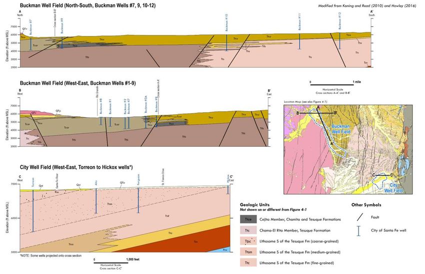
DRAFT Source Water Protection Plan
                     for the City of Santa Fe Water System
                                    Santa Fe, New Mexico
                                        PWS #3505126

                                     Prepared in coordination with

                            New Mexico Environment Department
                                       Drinking Water Bureau
                                         1190 S St Francis Dr
                                         Santa Fe, NM 87505

                                                DRAFT
                                               April 2021

                                     CONTACTS & RESOURCES
City of Santa Fe – Water Division
Alan Hook, Water Resources Coordinator Assistant / 505-955-4205 / aghook@santafenm.gov
https://www.santafenm.gov/water_division
New Mexico Environment Department – Drinking Water Bureau – Sustainable Water Infrastructure Group
Lena Schlichting, Source Water Protection Program Manager / 505-660-3391 / lena.schlichting@state.nm.us
https://www.env.nm.gov/drinking_water/source-water-protection/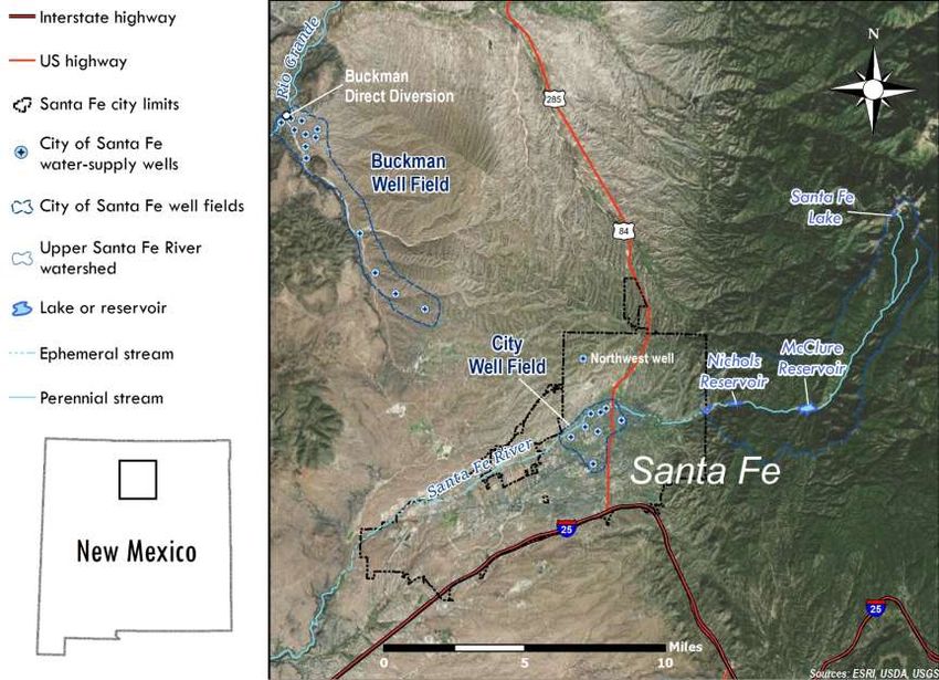
DRAFT
City of Santa Fe Water System                                                                                                                    April 2021
Source Water Protection Plan                                                                                                                        3 of 66

TABLE OF CONTENTS
  EXECUTIVE SUMMARY .............................................................................................................................. 5
  1.0   INTRODUCTION ............................................................................................................................. 6
      1.1        Protecting Your Drinking Water through Source Water Protection Planning .......................... 6
      1.2        Source Water Protection Program for Public Water Systems .................................................. 6
   2.0        SOURCE WATER PROTECTION PLANNING TEAM AND STAKEHOLDERS ....................................... 7
   3.0        WATER SYSTEM INFORMATION .................................................................................................... 7
      3.1        Historical Water Infrastructure ................................................................................................. 7
      3.2        Modern Water System .............................................................................................................. 9
   4.0        SETTING ....................................................................................................................................... 13
      4.1        Source Water Protection Area: City Well Field ....................................................................... 13
          4.1.1          Physical Geography and Geology .................................................................................... 13
          4.1.2          Climate and Hydrology .................................................................................................... 18
          4.1.3          Land Use and Population ................................................................................................ 18
      4.2        Source Water Protection Area: Buckman Well Field .............................................................. 18
          4.2.1          Physical Geography and Geology .................................................................................... 19
          4.2.2          Land Use .......................................................................................................................... 19
      4.3        Source Water Protection Area: Upper Santa Fe River Watershed ......................................... 19
          4.3.1          Physical Geography and Geology .................................................................................... 19
          4.3.2          Climate and Hydrology .................................................................................................... 21
          4.3.3          Land Use .......................................................................................................................... 22
   5.0   SOURCE WATER ASSESSMENT: POTENTIAL CONTAMINANT SOURCES AND OTHER THREATS .. 24
   6.0   RECOMMENDED ACTION ITEMS AND STRATEGIES .................................................................... 35
   REFERENCES ............................................................................................................................................ 59
   APPENDIX I Upper Santa Fe River Geomorphic Units ............................................................................. 63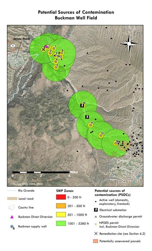
DRAFT
City of Santa Fe Water System                                           April 2021
Source Water Protection Plan                                               4 of 66

ABBREVATIONS AND ACRONYMS
ac-ft       acre-foot
BDD         Buckman Direct Diversion
bgs         below ground surface
BMP         best management practice(s)
BTEX        benzene, toluene, ethylbenzene, total xylenes
CAF         Corrective Action Fund
cfs         cubic feet per second
CSF         City of Santa Fe
CWA         Clean Water Act
DRO              diesel range organics
DWB              Drinking Water Bureau (NMED)
EDB              1,2-dibromoethane (ethylene dibromide)
EDC              1,2-dichloroethane (ethylene dichloride)
EPA              United States Environmental Protection Agency
gpm              gallons per minute
GRO              gasoline range organics
LANL             Los Alamos National Laboratory
LNAPL            light non-aqueous phase liquid
LUST             leaking underground storage tank
MCL              maximum contaminant level
MS4              Municipal Separate Storm Sewer System (NPDES permit)
NEPA             National Environmental Policy Act
NMAC             New Mexico Administrative Code
NMED             New Mexico Environment Department
NMWQCC           New Mexico Water Quality Control Commission
NPDES            National Pollutant Discharge Elimination System
ORO              oil range organics
PAH              polycyclic aromatic hydrocarbons
PCE              tetrachloroethylene
PNM              Public Service Company of New Mexico
PSOC             potential source of contamination
PSTB             Petroleum Storage Tank Bureau (NMED)
PWS              public water system
QWEL             Qualified Water Efficient Landscape
RCRA             Resource Conservation and Recovery Act
SCP              State Cleanup Program
SOC              source of contamination (implies actual source)
SWP              source water protection
SWPA             source water protection area
SWPP             source water protection plan
TCE              trichloroethylene
TPH              total petroleum hydrocarbons
TSCA             Toxic Substances Control Act
USFR             Upper Santa Fe River
USFS             United States Forest Service
USGS             United States Geological Survey
UST              underground storage tank
VOC              volatile organic compound
VRP              Voluntary Remediation Program

DRAFT
City of Santa Fe Water System                                                                     April 2021
Source Water Protection Plan                                                                         5 of 66

EXECUTIVE SUMMARY
The City of Santa Fe Water System is dedicated to providing a safe, reliable, and resilient water supply to
meet the community’s needs. Source waters that are secure both in quality and quantity are essential
for a high quality of life and the prosperity of the City and its residents. The purpose of this Source
Water Protection Plan is to provide an effective planning tool for the City of Santa Fe to protect its
sources of drinking water.

The City of Santa Fe Water System is unique among public water systems in the Southwest due to its
diverse portfolio of source waters, including two groundwater well fields, surface water from the Santa
Fe River stored in two reservoirs, and surface water from the San Juan-Chama Project obtained from the
Rio Grande at the Buckman Direct Diversion. The City purchases water from the latter, a separate public
water system, and only the groundwater and Santa Fe River source waters are discussed in this plan.

Organized municipal water use in Santa Fe has a long history that stretches back to the 17th century.
Population growth in the mid- to late 20th century required vast upgrades to the City’s water system,
which previously depended on water from the Santa Fe River only. The City and Buckman well fields
were developed in the 1950s and 1970s, respectively, and were used so extensively that groundwater
depletion was evident within only a few decades. More recently, the City has shifted back to using more
surface water, both from the Santa Fe River and the Rio Grande, greatly decreasing pumping pressure in
the well fields. This is the cornerstone of a more sustainable and resilient drinking water portfolio under
changing climatic conditions.

The New Mexico Environment Department (NMED) conducted an initial source water assessment for
Santa Fe in 2003 that was later revised by NMED’s contractor, Daniel B. Stephens & Associates Inc. The
current plan includes a source water assessment and contaminant source inventory that is up to date as
of spring 2021.

Source water areas are defined for each of the Santa Fe Water System’s 20 active groundwater wells
using either 15- or 35-year modeled capture zones (City Well Field) or a fixed-radius method (Buckman
Well Field) based on available data. The entire Upper Santa Fe River watershed above Two Mile
Reservoir is considered a source water protection area, within which sub-catchments have been
identified as having low to high post-fire threats, such as debris flows, capable of impacting the City’s
source water storage in McClure and Nichols reservoirs.

Existing and potential sources of contamination were identified and assessed for the level of risk (very
low to very high) they pose to the water supply within each source water protection area based on the
potential or actual impact to the water system and the probability of that impact occurring. The primary
risks to the City’s water supplies include contamination at the former Santa Fe Generating Station and
several leaking underground petroleum storage tank sites in the City Well Field; naturally occurring
arsenic and uranium in the Buckman Well Field; and potential wildfire-related threats in the Upper Santa
Fe River Watershed. Other risks are typically lower and include non-leaking underground petroleum
storage tanks, stormwater pollutants, arroyos and acequias, commercial enterprises such as automotive
facilities, private domestic or irrigation wells, and septic systems.

The City of Santa Fe Source Water Protection team has identified a series of action items and
recommendations key to preserving the quality and quantity of the City’s source waters. These include
improvements to ongoing water conservation programs, expanded outreach opportunities, regulatory
actions through ordinances, and additional monitoring and modeling efforts. This Source Water
Assessment and Protection Plan should be updated every two years with technical and public input.
DRAFT
City of Santa Fe Water System                                                                 April 2021
Source Water Protection Plan                                                                     6 of 66

1.0     INTRODUCTION

1.1     Protecting Your Drinking Water through Source Water Protection Planning

Access to safe, clean drinking water is a right to every New Mexican and is a key component in
maintaining a healthy and viable community. All drinking water sources are vulnerable to contamination
from a variety of human activities. Without attention to managing these potential sources of
contamination, communities will be faced with increased costs and potential loss of their drinking water
sources. Water sources in New Mexico are also highly vulnerable to depletion through unsustainable use
and drought. Careful planning for and monitoring of source water supplies are invaluable.

Applying proactive measures through source water protection planning is less expensive than
remediation and more reliable over the long term. If an aquifer that supplies drinking water to a
community becomes contaminated, the cost of restoring clean drinking water far exceeds the costs of
water treatment alone. The underlying principle in Source Water Protection (SWP) is that prevention is
the most effective and efficient method to assure long-term safe drinking water.

Source Water Protection Plans (SWPPs) go beyond a basic source water assessment to create an
effective management tool with strategies for protecting a community’s source of drinking water.
SWPPs not only provide a source water contaminant inventory and risk assessment, but include water
system and hydrogeologic information, source water area maps, best management practices, and action
items developed by the public water system through a public participation process.

The purpose of this document is to provide an effective planning tool for the City of Santa Fe Water
System to protect its sources of drinking water. This Source Water Protection Plan has been developed
in coordination with the New Mexico Environment Department (NMED) following standard guidelines
for source water plans developed by the U.S. Environmental Protection Agency (EPA) and NMED. This
document is designed to provide relevant information that informs sustainable source water
management and that can be easily updated.

1.2     Source Water Protection Program for Public Water Systems

The U.S. Congress amended the Safe Drinking Water Act in 1996 to provide for the assessment and
protection of sources of public water supply. The EPA provides guidance and encourages partnerships
for the voluntary process of source water protection planning. States, including New Mexico, completed
source water assessments between 2002 and 2006 for all public water systems and are now
implementing strategies to help local communities use and update the information obtained from these
assessments.

Source water protection plans are living documents designed to be updated and improved as a water
system acquires greater data and understanding of potential threats to its source water. This is
accomplished through multiple phases broadly categorized as assessment as described above
(determining contamination threats) or protection (planning and mitigation against those threats).
Figure 1-1 shows the basic components of source water protection.

DRAFT
City of Santa Fe Water System                                                                                 April 2021
Source Water Protection Plan                                                                                     7 of 66

                                                                   NMED Drinking Water Bureau’s Source Water
                                                                   Protection Program works with individual
                                                                   water systems, such as the City of Santa Fe
                                                                   Water System, with input from the
                                                                   community and other interested parties. The
                                                                   program assists in the development of a
                                                                   Source Water Protection Plan that is unique
                                                                   to each individual system and offers ways to
                                                                   identify potential sources of contamination
                                                                   and other threats to drinking water, while
                                                                   designing a plan that will protect water
                                                                   systems.

                                                                   2.0 SOURCE WATER PROTECTION
                                                                   PLANNING TEAM AND
                                                                   STAKEHOLDERS
                                                         The Source Water Protection Team (Table 2-
Figure 1-1 Elements of source water protection programs. SWAP =
source water assessment plan; SWPP = source water protection
                                                         1) plays a critical role in the development of
plan. Modified from Colorado Department of Public Health &
                                                         the source water assessment and protection
Environment – Water Quality Control Division.
                                                         plan as well as implementing
                                                         recommendations outlined in the plan.
Collaboration with water system representatives, water consumers, and community stakeholders will
ensure the success of the City of Santa Fe SWPP.

Table 2-1 City of Santa Fe Source Water Protection team
Name                  Title                                       Affiliation
 Alan Hook            Water Resources Coordinator Assistant       City of Santa Fe, Water Division
 Zoe Isaacson         River and Watershed Project Admin.          City of Santa Fe, Public Works-Engineering
 Melissa McDonald River and Watershed Manager                     City of Santa Fe, Public Works-Engineering
 Alex Puglisi         Environmental Compliance Specialist         City of Santa Fe, Water Division (former)
 Andy Jochems         Source Water Specialist                     NMED DWB Source Water Protection Program
 Lena Schlichting     Program Manager                             NMED DWB Source Water Protection Program
 Jill Turner          Group Manager                               NMED DWB Sustainable Water Infrastructure

3.0      WATER SYSTEM INFORMATION

3.1      Historical Water Infrastructure

Spanish expeditions to the Santa Fe area in 1590 and 1591 reported Tewa pueblo fields irrigated by
canal systems (Hammond and Rey 1966). The antiquity of these water systems is not well constrained,
but they were certainly front-runners to the numerous acequias found throughout northern New
Mexico, including two acequia madres constructed around the time that the Villa de Santa Fe was
established by royal charter in 1610. A 1776 report attests to the struggles of Santa Fe’s expanding
irrigation system (Adams and Chavez 1956):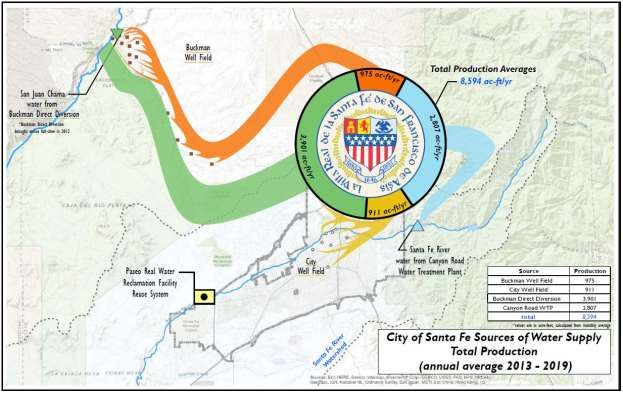
DRAFT
City of Santa Fe Water System                                                                           April 2021
Source Water Protection Plan                                                                               8 of 66

        Indeed, it [the Santa Fe River] is usually insufficient, at the best season for irrigating the
        farms, because there are many of them [acequias] it does not reach the lowest ones, for the
        first, being higher up, keep bleeding it off with irrigation ditches, and only in a rainy year is
        there enough for all.

By the late 19th century, Santa Fe’s expanding population and agricultural practices warranted new
efforts to boost the area’s water supply (Figure 3-1). Stone Dam was built by the Santa Fe Water and
Improvement Company on the Santa Fe River in 1881, creating a reservoir storage of about 25 acre-feet
(ac-ft). A 10-inch cast-iron pipe delivered water from the dam to Santa Fe Plaza with service lines for
residents along its 16,450-foot length (Smith 1957).

The City of Santa Fe was incorporated in 1891 and authorized Santa Fe Water and Improvement
Company to construct a new dam a half-mile downstream of Stone Dam on the Santa Fe River. Two Mile
Reservoir, so named for its location two miles from Santa Fe Plaza, was completed in 1893, breaching
and covering Stone Dam in the process (Duran and Thomas 2020). Two Mile Reservoir had a storage
capacity of 500 ac-ft. The New Mexico Office of the State Engineer and the Army Corps of Engineers
decommissioned the reservoir in 1992 due to hazardous and unstable conditions, and indeed the dam
was breached two years later (Lewis 1996).

                                                      Poor water pressure in the South Capital District led
                                                      the City to construct Atalaya Hill Reservoir in 1895.
                                                      This reservoir improved water pressure for residents
                                                      for more than 75 years before it was decommissioned
                                                      when a pump station was built at Canyon Road and
                                                      Camino Cabra (Duran and Thomas 2020).

                                                      The City relied solely on Santa Fe River water before
                                                      rapid population growth in the mid- to late 20th
                                                      century (Figure 3-2). The City Well Field began
                                                      operation in the late 1940s to early 1950s, coinciding
                                                      with a period of drought that lasted until about 1960.
                                                      Drilling in the Buckman Well Field began in the early
                                                      1970s, initiating several decades of increasing reliance
                                                      on groundwater that culminated with significant over-
                                                      pumping in the mid-1990s. The City purchased the
                                                      Sangre de Cristo Water Company from the Public
                                                      Service Company of New Mexico (PNM) in 1995.

                                                           The completion of Buckman Direct Diversion (BDD;
                                                           NM3502826) in 2011 represented a critical expansion
                                                           of the City’s drinking source water portfolio. This
                                                           marked the first diversion of San Juan-Chama Project
Figure 3-1 One of two original acequia madres in Santa Fe, surface water (via the Rio Grande) to Santa Fe.
New Mexico, ca. 1890. Photographer unknown. Courtesy       Vigorous conservation measures and initiatives paired
of Palace of the Governors Photo Archives (NMHM/DCA,
                                                           with this newly available source water have
Negative No. 055021).
                                                           diminished the City’s reliance on groundwater,
providing optimism for safer and more sustainable water resources under a changing climate in the 21st
century.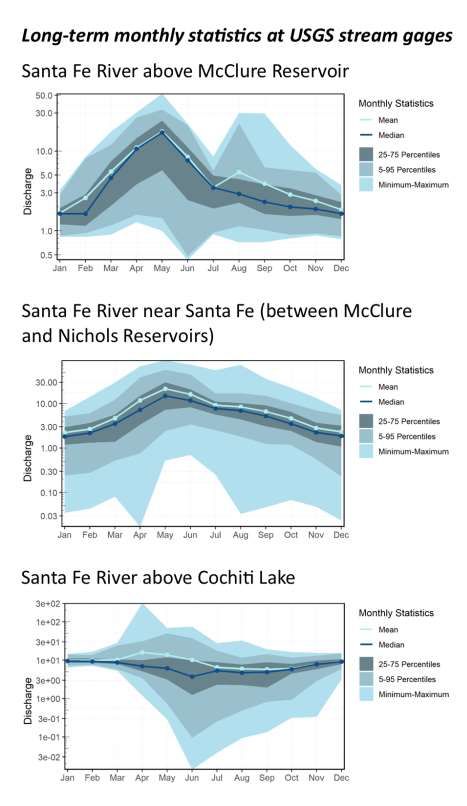
DRAFT
City of Santa Fe Water System                                                                                 April 2021
Source Water Protection Plan                                                                                     9 of 66

3.2      Modern Water System

The City of Santa Fe Water System is a public, community water system as defined by the New Mexico
Drinking Water Regulations 20.7.10 NMAC (New Mexico Administrative Code). The system directly
serves approximately 78,200 customers through 33,297 metered connections and sells water to four
public water systems:

      • Christus St. Vincent Medical Center (NM3580026)
      • Las Campanas Water System (NM3500626)
      • Santa Fe County South Sector (NM3500826)
      • Santa Fe County West Sector (NM3500926)

In total, the City of
Santa Fe system
serves a population
of 90,810, making it
the fourth-largest
system in New
Mexico.

The City of Santa Fe
Water System is
comprised of four
sources: surface
water from the
upper Santa Fe River
watershed, San Juan-
Chama surface water
purchased from BDD,
and groundwater
pumped from the         Figure 3-2 Population growth and water production for the City of Santa Fe over the period 1925-
Buckman and City        2019.
                        2019 Modified from City of Santa Fe Water Division.
well fields (Figure 3-
3). From 2013 to 2019, the approximate average contributions of Santa Fe River surface water, Rio
Grande surface water, and ground water were 35%, 45%, and 20%, respectively (Figure 3-4). However,
as much as 80% of the City’s water is derived from BDD at certain times of the year. The 2013-2019
average annual production from all sources was 8,600 ac-ft.

The City of Santa Fe Water System consists of the following infrastructure (NMED 2018):

      • 20 active production wells (13 Buckman Well Field, 7 City Well Field)
      • 2 surface water reservoirs
      • 1 connection to the Buckman Regional Water Treatment Plant where BDD water is treated
      • 8 consecutive connections (4 each to the Santa Fe County South and West Sector systems)
DRAFT
City of Santa Fe Water System                                                                     April 2021
Source Water Protection Plan                                                                        10 of 66

                                Figure 3-3 Geographic setting of City of Santa Fe water system.
DRAFT
City of Santa Fe Water System April 2021
Source Water Protection Plan 11 of 66
Table 3-1 Well information for the Buckman and City well fields
Static Date of Pump
Well Casing Casing 2017 Pump Depth to
Drill Water Static Rated Depth to Top of
Name Depth Depth Diameter Production Setting Bottom of
Date Level Water Capacity Screen (ft bgs)
(ft) (ft) (in) (ac-ft) (ft) Screen (ft bgs)
(ft bgs) Level (gpm)
Buckman – Active Wells
Well 1 1977 1,108 1,093 16 188.50 2015 95.16 546 840 257 1,093
Well 2 1977 1,593 1,473 16 107.12 2015 0.16 534 680 234 1,578
Well 3A 1995 1,500 1,490 1 138.67 2015 21.35 350 350 500 1,490
Well 4 1972 1,219 1,219 16 73.65 2015 — 374 750 454 1,214
Well 5 1972 1,182 1,182 16 154.51 2015 16.83 294 750 244 1,170
Well 6 1972 1,154 951 16 136.45 2015 1.81 766 730 291 1,148
Well 7 1990 1,415 700 16 167.06 2015 2.33 700 800 700 1,400
Well 8 1990 910 380 16 30.95 2015 63.91 530 620 380 900
Well 9 2002 1,363 1,336 16 / 12 181.10 2015 1.03 390 — 320 1,320
Well 10 2003 2,016 2,000 18 / 14 334.97 2015 47.21 1,100 — 500 1,980
Well 11 2003 2,020 — 18 / 14 396.41 2015 0.16 950 — 450 1,980
Well 12 2003 1,930 1,920 18 / 14 399.85 2015 0.12 850 — 400 1,900
Well 13 2003 2,018 2,000 18 / 14 315.41 2015 9.84 1,250 — 500 1,980
Buckman – Inactive Wells
Well 3 1972 1,500 — 16 — — — — — 500 1,480
City – Active Wells
Agua Fria 1951 740 740 16 174.80 2018 2,565.10 800 400 201 740
Alto 1968 741 725 12.75 201.00 2019 0.01 250 609 226 720
Ferguson 1970 826 750 14 227.00 2019 4.88 270 610 175 246
Northwest* 1998 2,000 500 14.625 475.87 2019 112.21 960 760 500 2,000
Osage 1971 809 770 — 116.80 2019 1.59 500 428 210 760
St. Michaels 1983 800 797 16 250.70 2018 0 490 714 382 782
Torreon 1997 1,230 1,230 16 103.70 2019 19.90 400 504 400 1,200
City – Inactive Wells
Acres Estates* 1947 410 — — — — — — — — —
Country Club* 1973 493 — — 303 2007 — — — — —
Hickox 1946 255 217 8 212.60 2019 — — — 76 210
Santa Fe 1951 1,523 725 16 308.60 2019 124 220 550 200 725
*These wells are not part of the City Well Field but are categorized as such for convenience.
ac-ft acre-feet (the volume needed to cover one acre in one foot of water; 1 ac-ft = 325,851 gallons)
bgs below ground surface
gpm gallons per minute
— not availableDRAFT
City of Santa Fe Water System April 2021
Source Water Protection Plan 12 of 66
• 7 treatment plants/units
• 12 booster/pump stations
• 9 storage tanks (combined storage volume of 35 million gallons)
• 12 pressure zones
• Approximately 565 miles of water mains
Figure 3-4 Average annual potable water production, 2013-2019. Modified from City of Santa Fe Water Division.
If needed, the City can move water between the pressure zones according to customer demand and
distribution pressures. Several zones include parts of Santa Fe County water systems.
Table 3-1 provides well construction and water level information for the Buckman and City well fields.
The City’s annual groundwater rights for the Buckman and City well fields are 10,000 ac-ft and 4,865 ac-
ft, respectively. In 2019, groundwater accounted for
only 7% of the City’s total production following a
robust winter snowpack (CSF 2020).
The City maintains two reservoirs, McClure and
Nichols, in the Upper Santa Fe River (USFR)
watershed with a combined storage capacity of
nearly 4,000 ac-ft. McClure Reservoir, originally
called Granite Point Reservoir, was completed in
1929 with a dam constructed of earth and concrete
(Figure 3-5). The dam was raised in 1935, 1947, and
Figure 3-5 Draining of McClure Reservoir in preparation for
again in 1995 when 500 ac-ft of storage rights
renovations, November 30, 1946. Photograph by T.H.
previously assigned to Two Mile Reservoir were Parkhurst. Courtesy of Palace of the Governors Photo
transferred for a total of 3,255 ac-ft (Lewis and Archives (NMHM/DCA, Negative No. 068847)
Borchert 2009). Granite Point Reservoir wasDRAFT
City of Santa Fe Water System April 2021
Source Water Protection Plan 13 of 66
renamed to McClure Reservoir in 1946 for Thomas M. McClure, New Mexico State Engineer in the 1930s
and 1940s (Townsend 2015).
After renovating Granite Point Reservoir in 1935, New Mexico Power Company applied for the
construction of Four Mile Reservoir which was completed in 1943 with a storage capacity of
approximately 775 ac-ft. Four Mile Reservoir was constructed in a similar fashion as McClure Reservoir
(earth and concrete) and its crest and spillway were renovated in 1995 and the early 2000s (Lewis and
Borchert 2009). It was renamed for C.H. Nichols, a major investor in the development of the upper Santa
Fe River watershed (Duran and Thomas 2020). Further information about McClure and Nichols
Reservoirs is provided in Table 3-2.
Table 3-2 McClure and Nichols Reservoir details
Maximum Maximum Normal USFR
Year Dam Dam
Name Discharge Storage Storage Drainage
Completed Length (ft) Height (ft)
(cfs) (ac-ft) (ac-ft) Area (mi2)
McClure Reservoir 1929 759 126 17,980 4,278 3,282 17.5
Nichols Reservoir 1943 622 91 19,690 1,234 679 22
NOTE: Information from New Mexico Office of the State Engineer
cfs cubic feet per second.
The City’s annual water right for McClure and Nichols Reservoirs is 4,000 ac-ft. Of this, 2,939 ac-ft are
subject to regulations of Rio Grande Compact Article VII, meaning that some or all of this amount may
be released from storage as part of New Mexico’s downstream obligations to Texas (Lewis and Borchert
2009). To date, the City has avoided this tenuous situation by utilizing relinquishment credits granted
when New Mexico delivers more than its annual obligation. The amount of water stored in the
reservoirs is monitored by U.S. Geological Survey (USGS) gaging stations 0831550 at McClure Reservoir
and 08316500 at Nichols Reservoir.
Additional information on the Santa Fe system, including water quality testing data, can be found on the
NMED’s Drinking Water Watch website at https://dww.water.net.env.nm.gov/NMDWW/ and the City of
Santa Fe Water Division website at https://www.santafenm.gov/water.
4.0 SETTING
4.1 Source Water Protection Area: City Well Field
4.1.1 Physical Geography and Geology
The City of Santa Fe is located in the southern Española Basin, a structural and hydrogeologic basin in
the Rio Grande rift region of the Basin and Range physiographic province. Most of the City lies on a low-
gradient piedmont plain formed where the ancestral Santa Fe River and smaller streams exited their
headwaters in the southern Sangre de Cristo Mountains, also known as the Santa Fe Range (Spiegel and
Baldwin 1963). The Santa Fe Range is the southern terminus of the Rocky Mountains.
North of Agua Fria Street and west to the village of Agua Fria, the Santa Fe River defines an approximate
boundary between a relatively flat but subtly terraced landscape to the south where most of the City of
Santa Fe is located and an upland area to the north known as Tano Ridge. The seven water-supply wells
of the City Well Field are located in the piedmont slope area except for the Northwest Well in the
upland Tano Ridge area.DRAFT City of Santa Fe Water System April 2021 Source Water Protection Plan 14 of 66 Both Tano Ridge and the gentle plain on which Santa Fe is located are underlain by sediments deposited in a Rio Grande rift basin that has gradually subsided over the last 30 million years (Koning et al. 2013). In a seminal study on the geology and hydrology of the Santa Fe area, Zane Spiegel and Brewster Baldwin of the U.S. Geological Survey named this basin-fill sediment the Santa Fe Group (Spiegel and Baldwin 1963). The Santa Fe Group is 2,500-3,000 feet thick in the vicinity of the City Well Field (Grauch et al. 2009). Certain formations within the Santa Fe Group host aquifers of varying area and depth. Of particular interest is the Tesuque Formation (Figure 4-1), a collection of channel, floodplain, and piedmont sediments deposited by the ancestral Santa Fe River and other streams on alluvial fans emanating from the Santa Fe Range mountain front (Smith 2000). Local geologic units, including the Tesuque Formation, are described in Table 4-1. It is important to distinguish between the different Tesuque Formation deposits in the subsurface because they have different aquifer properties. For example, one lithosome (a body of rock with uniform lithologic character) within the Tesuque Formation consists of permeable sandstones deposited in former channels of the ancestral Santa Fe River (Koning and Read 2010). The percentage of these channel deposits increases upward in the Tesuque Formation, and it is this lithosome that hosts the regional aquifer tapped by the City’s production wells. Beds of the Tesuque Formation are tilted 10-15° to the west (Hawley 2016), and the wells of the City field are therefore completed in different intervals of the formation (Figure 4-2). A thin (less than 75 ft) package of deposits overlying the Tesuque Formation is mostly unsaturated, but older homes and businesses in the City produced water from wells hand-dug to a shallow aquifer at the base of this zone (Lazarus and Drakos 1995). These sediments consist of permeable sand and gravel deposited again by an ancestral Santa Fe River and smaller tributaries exiting the Santa Fe Range but at a later time than the Tesuque Formation. The post-Tesuque deposits are grouped into: (1) the approximately 3.5- to 1-million-year-old Ancha Formation, the uppermost unit of the Santa Fe Group (Koning et al. 2002); and (2) three younger inset stream terrace deposits ranging in age from hundreds of thousands to only a few hundred years old (Hawley 2016). Santa Fe Plaza is located on the youngest terrace surface and the State Capitol is located on the oldest, although the elevation change between their surfaces is largely obscured by development. The shallow aquifer is primarily recharged along the Santa Fe Range mountain front. Some of this recharge water migrates to the deeper regional aquifer (Tesuque Formation) through seasonal infiltration along streambeds of modern arroyos and unlined acequias crossing the surfaces of older terrace deposits (Lazarus and Drakos 1995). Infiltration is especially focused at high-permeability fractures, faults, or bedding planes acting as conduits between the Tesuque Formation and younger deposits above it. As a result, the shallow aquifer is typically not observed in wells located more than 1.5 miles from the mountain front, and nowhere does it produce sufficient water for municipal use. The role of soils in infiltration and other processes of the hydrologic cycle is diminished in the City Well Field due to the prevalence of paved, impermeable surfaces.
DRAFT
City of Santa Fe Water System                                                                                                                                April 2021
Source Water Protection Plan                                                                                                                                   15 of 66

             Figure 4-1 Generalized geologic map of the Santa Fe area encompassing the Buckman and City well fields. Modified from Koning and Read (2010).
DRAFT
City of Santa Fe Water System April 2021
Source Water Protection Plan 16 of 66
Table 4-1 Descriptions for lithologic units in the Santa Fe area as shown in Figure 4-1 (modified from Koning and Read 2010)
Abbreviation Unit Name Brief Description
afe Artificial fill or excavations Deposits under highways or in landfills
Qva* Valley-fill alluvium Sand and gravel deposited in valley floors and often cut by arroyos
Qfa Alluvial fan deposits Gravel and sand deposited in fan-shaped lobes at the mouths of drainageways
Qms Mass-wasting, colluvial, and sheetwash deposits Sheetflood sand, coarse landslide or slump deposits, and gravelly talus or colluvium
Qst Stream-terrace deposits Sand and gravel underlying terraces perched above active drainageways
Ash and ash-flow tuffs resulting from powerful eruptions of the Valles caldera over the
Qvc Volcanic rocks originating from the Valles caldera
last 1,600,000 years
QTo Other Quaternary-Tertiary deposits (sand or gravel) Gravel and sand consisting of volcanic rocks deposited east of the Caja del Rio Plateau
Sandy gravel underlying terraces on Tano Ridge and north of the Río Tesuque that are
QTgo Older high-level stream gravel deposits
perched higher above active drainageways than those of unit Qst
Basaltic to andesitic rocks capping the Caja del Rio Plateau or monzonitic intrusive
QTv Volcanic rocks originating from east of the Rio Grande
rocks near La Cienega
Santa Fe Group
Sand and gravel derived from the southwestern Sangre de Cristo Mountains and
QTa* Ancha Formation
deposited on alluvial slopes
Volcanic-rich gravel, sand, and silt deposited by streams and debris flows west of the
QTp Puye Formation
Rio Grande
Tcar* Axial-river deposits of the Chamita Formation Sandstones deposited by the ancestral Rio Grande
Ttcu Cuarteles Member of the Tesuque Formation Conglomerate and sandstone deposited on alluvial slopes
Tcarc Interfingering Chamita Fm and Cuarteles Mbr Complexly interfingering conglomerate and sandstone of units Tcar and Ttcu
Sandstone and subordinate mudstone deposited on alluvial slopes that complexly
Tta Lithosome A of the Tesuque Fm
interfingers and grades laterally or vertically into units Ttb, Tts, and Ttcu
Ttb Lithosome B of the Tesuque Fm Claystone, siltstone, and sandstone deposited on floodplains in a basin-floor setting
Pebbly sandstone, siltstone, and mudstone deposited by the ancestral Santa Fe River
Tts* Lithosome S of the Tesuque Fm
in its channel or on its floodplain
Ttas Mixed lithosomes A and S of the Tesuque Fm Gradational zone between units Tta and Tts northwest of the Pueblo of Tesuque
Older Rocks
Includes ash-rich sandstone and siltstone of the Abiquiu Formation, alluvial-fan
sandstone and conglomerate or tuffaceous sandstone of the Espinaso Formation,
Tos Sedimentary, volcaniclastic rocks under the Santa Fe Group
stream-deposited sandstone of the Galisteo Formation, and limestone- to granite-
bearing sandstone and conglomerate near Bishops Lodge
Pzu Paleozoic rocks Limestone, siltstone, shale, and sandstone
XYu Proterozoic rocks Granite, pegmatite, and amphibolite of the southern Sangre de Cristo Mountains
*Unit known to host either shallow or deep aquifers.DRAFT
City of Santa Fe Water System April 2021
Source Water Protection Plan 17 of 66
Figure 4-2 Geologic cross sections through the
Buckman and City well fields, showing key
hydrostratigraphic units. The Tesuque Formation
hosts the regional aquifer tapped by Santa Fe’s
water-supply wells but its lithology varies from
place to place (e.g., coarse- versus fine-grained
sub-units).DRAFT
City of Santa Fe Water System April 2021
Source Water Protection Plan 18 of 66
4.1.2 Climate and Hydrology
The average annual temperature for the City
of Santa Fe over the years 1981-2010 is 51°F
with highs reaching into the mid-90s and lows
in the mid-teens (WRCC 2020). The average
annual precipitation in the City is 14.2 inches,
most of which occurs as summer monsoon
rainfall during late June to September. The
Köppen-Geiger climate classification, a
commonly used climate index, places Santa
Fe in class Bsk indicating a semi-arid, steppe-
like climate with cold winters.
4.1.3 Land Use and Population
The City of Santa Fe was established in 1610
and has served as New Mexico’s capital since
that time. In addition to its status as an
administrative seat, the city has long been a
center for agrarian, commercial, intellectual,
and tourism activities in north-central New
Mexico and land use in the Santa Fe area has
evolved dramatically over time.
Today, Santa Fe is the fourth largest city in
the state with an estimated 2019 population
of 84,683 (USCB 2020). The area is mostly
Figure 4-3 Zone types within the City of Santa Fe showing locations
urbanized though vestiges of the city’s past
of water supply wells in the City Well Field. Note that residential
abound in the form of historic architecture zones are grouped together based on intended density and urban
and an acequia system more than 400 years form.
old. Over 50% of the city is zoned for
residential use with another 27% for commercial, office, and retail and about 5% for industrial uses
(Figure 4-3). The seven active supply wells of the City Well Field are located in single- or multiple-family
zones, except for St. Michaels Well which is located in a general commercial district.
Older homes and businesses in Santa Fe produced water from hand-dug wells that were typically 15 to
40 ft deep. These wells depended on surface recharge to the shallow aquifer, which declined over time
due to the transfer of water rights from surface to groundwater (Lazarus and Drakos 1995). Dwindling
flows in unlined acequias, decreasing flood irrigation, and extensive paving of surface across the City led
to most shallow wells drying up after the mid-1960s.
Pumping of the City wells caused groundwater levels to fall as much as 180 feet from 1951 to the mid-
1990s as well as cones of depression (drawdown) surrounding the well field (Lazarus and Drakos 1995).
A reduction in pumping since 2011 and increases in Santa Fe River flows have helped lessen drawdown,
although cones of depression are still apparent in spatial groundwater-level patterns, particularly
around St. Michaels Well (JSAI 2019).
4.2 Source Water Protection Area: Buckman Well FieldDRAFT City of Santa Fe Water System April 2021 Source Water Protection Plan 19 of 66 4.2.1 Physical Geography and Geology The Buckman Well Field consists of 13 wells in an area of about 12 mi2 located 8-15 miles northwest of Santa Fe. Nine Buckman wells (1-8 and 3A; Table 3.1) were drilled in the 1970s to 1990s on the east side of the Rio Grande directly across from the town of White Rock. Buckman Wells 9-13 were drilled in the early 2000s. Like the City Well Field, the Buckman wells rely on a regional aquifer hosted by the Tesuque Formation of the Santa Fe Group. A key difference is that the Tesuque Formation at Buckman Wells 1-9 and 3A consists of sediments deposited in a greater diversity of environments, including distal piedmont (far from the mountain front), fluvial (river deposits of the ancestral Rio Grande), and basin floor (Figure 4-1; Koning et al. 2007). There is considerably more interfingering of sediments ranging from sand- and gravel-dominated to more impermeable muds and clay (Figure 4-2). Buckman Wells 1-8 and 3A are screened across permeable sands and gravels of the ancestral Rio Grande, whereas Well 9 is screened across finer-grained deposits and exhibits lower yield as a result (Koning et al. 2007). Artesian conditions at Wells 1-9 result from westward flow down the dip of west- northwest-tilted beds in the Tesuque Formation and deep groundwater flow that rises along fault zones (JSAI 2012). Buckman Wells 10-13 penetrate deposits of similar grain size as Wells 1-8 but belonging to the same ancestral Santa Fe River lithosome as the Tesuque Formation sediments penetrated by the City Well Field. These wells were drilled under artesian conditions that no longer exist as suggested by flattening hydraulic gradients (JSAI 2020). 4.2.2 Land Use The original portion of the Buckman Well Field (Wells 1-9, 3A) is located at and around the former settlement of Buckman, a station on the narrow-gauge Denver and Rio Grande railroad (Julyan 1998). Buckman was abandoned in the early 20th century and today the Buckman wells are located on U.S. Bureau of Land Management (BLM) or Forest Service land. Wells 1-9 and 3A are sited between the BLM Diablo Canyon Recreation Area to the south and the Rio Grande to the northwest. Scenes from several modern western movies have been filmed at the recreation area. 4.3 Source Water Protection Area: Upper Santa Fe River Watershed 4.3.1 Physical Geography and Geology The Santa Fe River watershed covers 245 mi2 in north-central New Mexico, of which 27 mi2 are located in the Upper Santa Fe River (USFR) sub-watershed above the former Two Mile Reservoir (Figure 4-4). The Santa Fe River flows approximately 44 miles from its headwaters at Santa Fe Lake in the Sangre de Cristo Mountains to the Rio Grande just below Cochiti Dam. The total relief (elevation difference) of the Santa Fe River watershed is 7,195 feet, and the relief of the USFR sub-watershed is 5,061 ft. The Santa Fe River is located in the Rio Grande rift tectonic province, except for the USFR which originates in the Southern Rocky Mountains. The geology along its course is highly variable, from crystalline igneous rocks such as granite, gneiss, and quartz pegmatite in the southern Sangre de Cristo Mountains (Bauer et al. 1996) to basin-fill sediment of the Santa Fe Group, basaltic and andesitic lava
DRAFT
City of Santa Fe Water System                                                                                     April 2021
Source Water Protection Plan                                                                                        20 of 66

              Figure 4-4 Digital shaded relief map of the Santa Fe River watershed in the vicinity of Santa Fe.

flows, and young alluvium below Two Mile Reservoir (Koning and Read 2010). Paleozoic limestone and
sandstone crop out along a short reach of the river from Two Mile Reservoir to Arroyo Saiz.

Soils play a critical role in the hydrologic cycle because their properties affect the rates at which
precipitation infiltrates into underlying aquifers or runoff travels laterally through the unsaturated zone
or along the surface toward stream channels. A number of different soil units, distinguished by their
physical characteristics such as depth, texture, and composition, are found in the USFR watershed but
only a few are common. Steep, rocky slopes in the granitic terrain are dominated by soils of the
Broadmoor family-Rock outcrop and Mirabal-Ashbray families Rock outcrop complexes (Soil Survey Staff
2020). These soil units are well-drained and characterized by their position on steep slopes (at least 15-
25°) and gravelly composition.

Floodplains of the Santa Fe River and its tributaries in the USFR watershed are characterized by three
soil complexes that cover a much smaller surface area than the Broadmoor-Mirabal-Ashbray-Rock
outcrop complexes. These include the Morenda-Fiesta-Dula, Riomedio stony-Tricorner families, and
Riomedio-Uwing complexes (Soil Survey Staff 2020). These units are somewhat poorly to well-drained
and are found on flat ground to moderate slopes (0-35°). Their parent material is mixed stream alluvium
and as a result their composition ranges from clayey or loamy to sandy or gravelly. The water table often
lies no more than 1-3 ft below the surface of these valley-floor soils.
DRAFT
City of Santa Fe Water System April 2021
Source Water Protection Plan 21 of 66
4.3.2 Climate and Hydrology
There are no climate stations in the USFR watershed with records comparable to those for the City of
Santa Fe. However, the Gascon station (293488) in Mora County approximately 25 miles northeast of
McClure Reservoir has a representative climate because it is located in the Sangre de Cristo Mountains
at an elevation of 8,250 feet above sea level. The 1981-2010 average annual temperature at Gascon is
44° with highs in the high-70s to low-80s and lows in the mid-teens (WRCC 2020). The average annual
precipitation at Gascon is 26 inches, much of which falls as summer monsoon rainfall but includes a
greater amount of snowfall than lower-lying areas. The Köppen-Geiger climate classification places most
of the USFR watershed in class Dfb indicating a cold, continental climate with cool summers and no
distinct dry season (Beck et al. 2018).
The Santa Fe River crosses three hydrogeologic basins: a mountainous basin confined to relatively
narrow canyon floors in the southern Sangre de Cristo range, the Española Basin from Santa Fe to La
Bajada Hill, and the Santo Domingo Basin in its reach below La Bajada. The river flows perennially (year-
round) in the mountainous USFR watershed but is ephemeral (flows only in response to runoff from
precipitation) in its lower reaches (Figure 4-5). However, the City holds a discharge permit at its
wastewater treatment plant near Santa Fe Regional Airport and the Santa Fe River flows downstream to
La Bajada for part of the year as a result. Discharge (flow) data for the Santa Fe River is shown in Table 4-
2.
Table 4-2 Select USGS stream gages and flow statistics on the Santa Fe River listed upstream to downstream
Max Min Mean Mean
Gage Name
Period of Record1 Discharge Discharge Discharge Discharge (cfs)
USGS No.
(cfs) (Year) (cfs) (Year) (cfs) 2010-2019
Above McClure
Reservoir (8 ft flume) 7/1998 – 10/2020 199 (2013) 0.05 (2002) 5.59 5.48
083154802
Above McClure Reservoir
(1.5 ft flume) 9/2001 – 9/2007 16.5 (2004) 0 (mult) 1.55 --
2
08315479
Near Santa Fe (between
McClure and Nichols) 2/1913 – 10/2020 378 (1929) 0 (mult) 7.81 5.84
08316000
Above Cochiti Lake
3/1970 – 10/2020 1000 (1992) 0 (mult) 9.35 4.91
08317200
1Allgages have period of record gaps of varying duration.
2The flumes above McClure Reservoir were replaced with a Replogle flume (broad-crested weir) in 2012. Measured flows
before and after 2012 may not be directly comparable.
A changing climate may hold potentially serious consequences for dependable flow in the Santa Fe River
watershed and other basins of the Southwest. Stream flows above McClure Reservoir have been
projected to decrease by 11-18% of their 1950-1999 levels by the year 2060 (Cox et al. 2011). Decreased
snowpack and earlier spring runoff along with increased drought and wildfire frequency are all possible
effects of climate change that can impact the quality and quantity of surface water flows, even if
scenarios of lower greenhouse gas emissions are achieved (Figure 4-6).DRAFT
City of Santa Fe Water System April 2021
Source Water Protection Plan 22 of 66
4.3.3 Land Use
The USFR watershed is
located in the Santa Fe
National Forest but is
closed to the public to
protect the Santa Fe
River source waters.
The upper 10,000 acres
of the watershed are
located in the Pecos
Wilderness Area.
Archeological sites and
historic properties in
the USFR watershed
suggest that people
have used the Santa Fe
River and its environs
since prehistoric times
(Duran and Thomas
2020). Homesteaders,
ranchers, and farmers
visited and lived in the
area during the 17th
and 18th centuries
raising livestock,
cutting timber, and
acquiring water from
the Santa Fe River.
Small check dams
constructed for
watering livestock are
found in certain high
drainages such as the
sub-catchment directly
to the north of McClure
Reservoir.
Significant
development of the
USFR watershed began
in the late 1800s with
the establishment of
labor camps for
Figure 4-5 Monthly statistics for flow on the Santa Fe River at three stream gages (period of prisoners of the New
record; see Table 4-2). Discharge is in cubic feet per second (cfs).DRAFT
City of Santa Fe Water System April 2021
Source Water Protection Plan 23 of 66
Figure 4-6 Historical and projected average daily maximum temperatures in Santa Fe
based on low- and high-emission scenarios. Data from NOAA ClimateExplorer.
Mexico Territorial Penitentiary (Torrez 2004). A ranger station operated in the lower canyon during the
early 1900s and the High Line Ditch was constructed to transmit water from below the location of
modern-day Nichols Reservoir to Santa Fe’s
first hydroelectric power plant built in 1895 on
Canyon Road. The USFR has been closed to
unauthorized access since 1932 to protect the
City’s water supply (Figure 4-7; USDA 2001).
The City of Santa Fe has partnered with the
U.S. Forest Service and the New Mexico
Finance Authority Water Trust Board since the
early 2000s to conduct wildfire mitigation
projects in the USFR watershed. In 2001,
approximately 7,300 acres of dense
ponderosa pine forest were thinned and
treated with prescribed burns in the vicinity of
the City’s active water supply reservoirs (Lewis
Figure 4-7 The upper Santa Fe River watershed has been closed to
2018). An additional 5,500 acres were treated
public access since 1932.
in the non-wilderness portion of the USFR
between 2003 and 2009 (Margolis et al.DRAFT
City of Santa Fe Water System April 2021
Source Water Protection Plan 24 of 66
2013). Prescribed burns have been proposed for ponderosa and mixed conifer forests in the Pecos
Wilderness portion of the USFR watershed above McClure Reservoir (USDA 2014), but this work has yet
to occur. Fire mitigation is further discussed in Section 6.4.
5.0 SOURCE WATER ASSESSMENT: INVENTORY OF POTENTIAL CONTAMINANT
SOURCES AND OTHER THREATS
5.1 Overview of Potential Contaminant Sources and Risk Assessment
Potential sources of contamination (PSOCs) are defined as any possible site or event that could, under
any circumstance and time frame, lead to contamination of drinking water sources. Not all sites
identified as PSOCs pose the same level of risk. Depending on the type of PSOC, some sites may pose
little to no contamination risk, while others may pose an imminent threat. Sources of contamination
(SOCs) are considered those activities or environmental accidents that are currently threatening or
contaminating the source water.
Source water protection areas (SWPA) were delineated based on the best available data. Hydrogeologic
modeling for the City Well Field allowed for SWPAs based on 15- and 35-year capture zones, i.e.
geographic areas over which a single particle of groundwater travels over the given timeframe to the
well (CDM 1992; JSAI unpublished data). Such modeling was not available for the Buckman Well Field
and fixed radii (0-200 ft, 201-500 ft, 501-1000 ft, and 1001-5280 ft) were used instead. Finally, the Upper
Santa Fe River SWPA is considered to be the entire USFR watershed because moderate to severe
wildfires could generate sediment and other contaminants reaching the river from all portions of its
catchment.
Following the identification of PSOCs and SOCs in the City’s SWPAs, a risk assessment was performed for
each contaminant. This methodology is based on a technique developed by the Colorado Rural Water
Association (e.g., CRWA 2017) and involves estimation of risk using two parameters:
1. Probability of Impact – The risk to source waters increases as the relative probability of damage or
loss increases. The probability of impact is determined by evaluating the number of contaminant
sources, the migration potential or proximity to the water source, and the historical data. The following
descriptions provide a framework to estimate the relative probability that damage or loss would occur
within one to ten years.
Certain: >95% probability of impact
Likely: >70% to 30% to 5% toDRAFT
City of Santa Fe Water System April 2021
Source Water Protection Plan 25 of 66
Major: Substantial damage to the water source(s). This could include a loss of use for an
extended period of time and/or the need for new treatment technologies.
Significant: Moderate damage to the water source(s). This could include a loss of use for an
extended period of time and/or the need for increased monitoring and/or maintenance
activities.
Minor: Minor damage resulting in minimal, recoverable, or localized efforts. This could include
temporarily shutting off an intake or well and/or the issuance of a boil order.
Insignificant: Damage that may be too small or unimportant to be worth consideration but may
need to be observed for worsening conditions. This could include the development of
administrative procedures to maintain awareness of changing conditions.
The probability of impact and impact to the public water system parameters are then combined in a risk
assessment matrix to qualify the risk of a given contaminant (Figure 5-1).
Certain Low Moderate High Very High Very High
Probability of Impact
Likely Low Moderate High High Very High
Possible Low Moderate Moderate High High
Unlikely Very Low Low Moderate Moderate Moderate
Rare Very Low Very Low Low Low Low
Insignificant Minor Significant Major Catastrophic
Impact to Water System
Figure 5-1 Risk assessment matrix used for City of Santa Fe PSOCs and SOCs
(after the Colorado Rural Water Association’s Source Water Assessment and Protection Program).
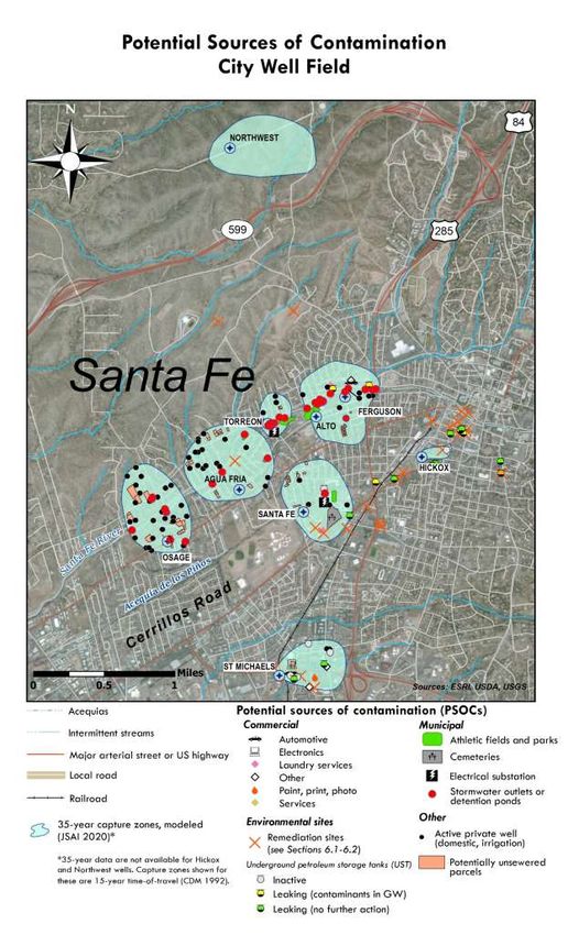
Locations of SOCs and PSOCs for the City of Santa Fe Water System are found on the following source
water protection area maps for the Buckman and City well fields (Figures 5-2 and 5-3). A full list of SOCs
and PSOCs for the City and Buckman wells and assigned risk levels are found in Tables 5-1 and 5-2. The
“Control” column refers to the level of control that the City has over a given PSOC or SOC, including
regulatory controls in conjunction with NMED.
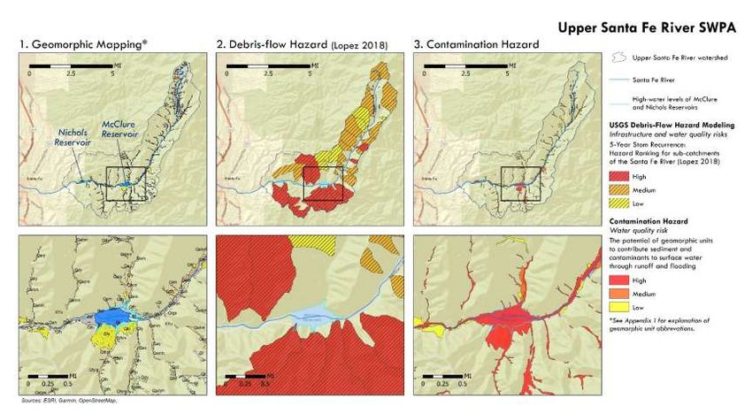
Wildfire-related impacts are considered to be the greatest threat to the Upper Santa Fe River watershed
and potential debris-flow and contamination hazards are shown at the sub-catchment scale in Figure 5-
4.DRAFT
City of Santa Fe Water System April 2021
Source Water Protection Plan 26 of 66
Figure 5-2 Source water protection areas and PSOCs for the Buckman Well Field.DRAFT
City of Santa Fe Water System April 2021
Source Water Protection Plan 27 of 66
Figure 5-3 Source water protection areas and PSOCs for the City Well Field.DRAFT City of Santa Fe Water System April 2021 Source Water Protection Plan 28 of 66 Figure 5-4 Source water protection area and hazards for the Upper Santa Fe River. PSOCs in the watershed include excess sedimentation, ash, and trace metals generated during runoff and debris flows following potential stand-replacing wildfires.
DRAFT
City of Santa Fe Water System April 2021
Source Water Protection Plan 29 of 66
Table 5-1 Contaminant source inventory for the City Well Field. See Figure 5-1 for risk assessment criteria
Actual (A) or
Probability
Well PSOC Type PSOC Description # Potential (P) Impact to PWS Risk Control Explanation
of Impact
Contamination
City Well Field
Agua Fria Abatement site Used oil spill 1 A Possible Insignificant Low Direct Closed
Arroyos — 3 P Unlikely Minor Low Direct/Indirect City operates upper Santa Fe River dams
Dirt roads — 9 P Unlikely Minor Low Indirect
MSD Storm drainage collection areas or outlets (unlined) 4 P Unlikely Minor Low Indirect City manages stormwater system
Parks / Athletic Fields — 1 P Rare Insignificant Very Low Direct
PDW Private domestic wells 18 P Rare Minor Very Low None
Primary roads — 1 P Likely Minor Moderate Indirect
RSF Single family residences, unsewered 19 P Rare Minor Very Low Indirect Sewered/unsewered status unconfirmed
1
Alto-Ferguson Arroyos — 3 P Unlikely Minor Low Direct/Indirect City operates upper Santa Fe River dams
CAR Automotive repair shops 1 P Rare Minor Very Low Indirect
Cleanups at Alto Park, Exxon W Alameda, and NewMexigas
CFB/CSS Leaking underground storage tank (LUST) site 3 A Certain Minor Moderate None
LUSTs. Contaminants now below water quality standards
CCW Car washes 1 P Possible Minor Moderate Indirect
Dirt roads — 4 P Unlikely Minor Low Indirect
Laundromat — 1 P Rare Significant Low Indirect
MSD Storm drainage collection areas or outlets (unlined) 13 P Unlikely Minor Low Indirect City manages stormwater system
Parks / Athletic Fields — 2 P Rare Insignificant Very Low Direct
PDW Private domestic wells 7 P Rare Minor Very Low None
Primary roads — 2 P Likely Minor Moderate Indirect
RSF Single family residences, unsewered 18 P Rare Insignificant Very Low Indirect Sewered/unsewered status unconfirmed
2
Hickox Abatement site Used oil LUST site (Garcia Honda) 1 A Possible Insignificant Low None Closed
CFB Underground storage tanks 1 P Unlikely Minor Low None
Primary roads — 2 P Likely Minor Moderate Indirect
Northwest2 Arroyos — 1 P Unlikely Insignificant Very Low Indirect
Dirt roads — 7 P Unlikely Minor Low Indirect
Osage Abatement site Osage Well 1 A Certain Insignificant Low Direct Closed
ADC Irrigation wells 4 P Rare Minor Very Low None
Arroyos — 2 P Unlikely Minor Low Direct/Indirect City operates upper Santa Fe River dams
Dirt roads — 13 P Unlikely Minor Low Indirect
MSD Storm drainage collection areas or outlets (unlined) 7 P Unlikely Minor Low Indirect City manages stormwater system
PDW Private domestic wells 25 P Rare Minor Very Low None
Primary roads — 1 P Likely Minor Moderate Indirect
RSF Single family residences, unsewered 17 P Rare Minor Very Low Indirect Sewered/unsewered status unconfirmed
Santa Fe Abatement site Berridge Distributing Co 1 A Possible Insignificant Low Direct Closed
Abatement site PNM Santa Fe Generating Station 1 A Certain Major Very High Direct
ADC Drainage canals, ditches or acequias (unlined) 1 P Rare Minor Very Low Indirect
ADC Irrigation wells 2 P Rare Minor Very Low None
CCE Cemeteries 1 P Unlikely Minor Low Indirect
CFB/CSS Leaking underground storage tank (LUST) site 1 A Possible Insignificant Low None
CST Commercial septic tanks/leachfields/leachpits/cesspools 1 P Rare Insignificant Very Low Indirect Sewered/unsewered status unconfirmed
Dirt roads — 3 P Unlikely Minor Low IndirectYou can also read