PRIVATE WATER WELLS - KDHE
←
→
Page content transcription
If your browser does not render page correctly, please read the page content below
Chapter I
               PRIVATE WATER WELLS
INTRODUCTION                           4
WELL LOCATION                          4
 MICROORGANISM PROTECTION              4
 PROTECTION FROM OTHER CONTAMINANTS   10
 CONE OF DEPRESSION                   10
 LOCATING A NEW WELL                  12
WELL CONSTRUCTION                     12
 DRILLED WELLS                        14
 DRIVEN WELLS                         14
 DUG WELLS                            14
 WELL CASING                          14
 WELL GROUTING                        18
 WELL SCREEN AND GRAVEL PACK          19
 WELL DEVELOPMENT                     19
 SANITARY WELL SEAL                   20
DISINFECTION OF WELL                  20
WELL PUMPS                            23
 POWER PUMPS                          23
 HAND PUMPS                           26
FREEZE PROTECTION                     27
 WELL PUMP HOUSE                      27
 PITLESS INSTALLATIONS                28
WELL MAINTENANCE                      31
 WATER TESTING                        33
 DRINKING WATER STANDARDS             33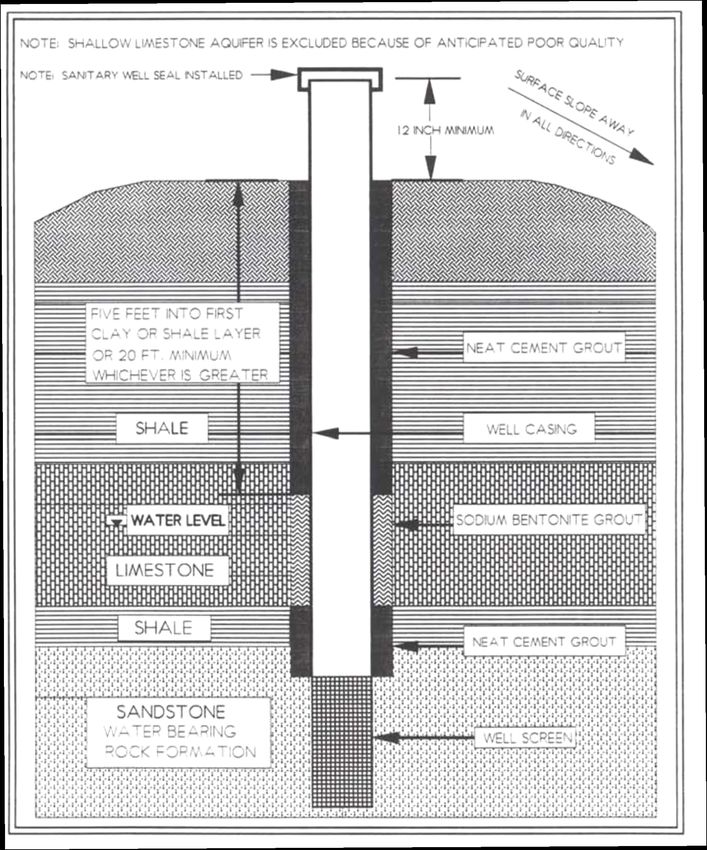
PROTECTION OF WELLS (WELLHEAD PROTECTION)                  34
PRESSURE TANKS                                             36
WATER STORAGE TANK                                         37
CROSS-CONNECTION CONTROL                                   38
COMPLAINT INVESTIGATION AND EVALUATION OF EXISTING WELLS   40
PLUGGING ABANDONED WELLS                                   40
REFFERENCES AND READING MATERIALS                          41

PROTOCOLS

 EVALUATION OF A NEW WELL SITE OR AN EXISTING PRIVATE WELL 44

APPENDICES

 APPENDIX A. WELL DISINFECTION                             50
 APPENDIX B. COMMON INORGANIC DRINKING WATER QUALITY
 PARAMETERS                                                52
 APPENDIX C. KDHE PRIVATE WELL WATER QUALITY SCREENING
 RESULTS INTERPRETATION                                    60
 APPENDIX D. EVALUATION OF TASTE AND ODOR COMPLAINTS
 (TROUBLE SHOOTING GUIDE)                                  62
TABLES

 I-1. PUBLIC AND PRIVATE WATER SYTEMS IN KANSAS               6
 I-2. MINIMUM AND RECOMMENDED SEPARATION DISTANCES FROM
 PRIVATE WELLS                                                8
 I-3. PRIVATE WELL 12-POINT MAINTENANCE CHECK                32
 I-4. RELATIVE CONTAMINATION RISKS FOR HOME AND FARMSTEAD
 ACTIVITIES                                               35

FIGURES

 I-1. SITE FEATURES SHOWING MINIMUM AND RECOMMENDED
 SEPARATION DISTANCES                                         9
 I-2. CONE OF DEPRESSION FOR A PUMPING WELL                  11
 I-3. GOOD WELL LOCATION AND SEPARATION DISTANCES FOR A
 FARMSTEAD                                                   13
 I-4. CONSTRUCTION OF A DRILLED WELL IN AN UNCONSOLIDATED
 FORMATION                                                   15
 I-5. CONSTRUCTION OF A DRILLED WELL IN A CONSOLIDATED ROCK
 FORMATION                                                  16
 I-6. CONSTRUCTION OF A DRIVEN WELL                          17
 I-7. SANITARY WELL SEALS                                    22
 I-8. SUBMERSIBLE PUMP COMPONENTS                            24
 I-9. TWIN TUBE JET PUMP COMPONENTS FOR DEEP WELL            25
 I-10. SANITARY HAND PUMP COMPONENTS                         26
 I-11. TYPICAL PUMP HOUSE COMPONENTS                         29
 I-12. TYPICAL PITLESS WELL DEVICE                           30
 I-13. DESIGN OF TYPICAL PITLESS UNIT AND PITLESS ADAPTER.   31
 I-14. PRESSURE TANK STYLES                                  37
 I-15. BAYLIS CURVE SHOWING ZONES OF SEVERE, INTERMEDIATE,
 AND NO CORROSION                                            58
2020

INTRODUCTION
A reliable and safe water supply is important to every household, business, church, and
institution. While public supplies are regulated by KDHE to ensure that they meet safe drinking
water standards, the quality of private supplies is the sole responsibility of the owner and/or
water user. There is no federal or Kansas law that regulates drinking water quality from private
water wells. This chapter of the Environmental Health Handbook discusses in detail the basic
principles for a reliable and safe water supply and includes an inspection protocol for new or
existing wells.

The 1990 Census data showed Kansas has more than 109,000 private water supplies (mostly
wells), which supply about 11 percent of the total housing units in the state. The most populous
counties tend to have more private wells. Conversely, twenty-nine Kansas counties each have
more than 1,000 private wells. Twenty-eight counties, mostly in sparsely populated areas of the
state, have fewer than 500 private drinking water wells each. In eastern Kansas, rural water
districts cover much of the rural area, especially where there is no principal groundwater aquifer.
Table I-1 summarizes private and public water supplies for each Kansas County.

Obtaining safe water from a private well should be relatively simple, but it requires carefully
following some basic principles. Simply stated, safe water is most reliably obtained from a safe
well. A safe well is one that meets the following conditions:

   •   Located away from potential contamination sources and out of possible pollutant
       pathways from both surface and groundwater flows.
   •   Meets current KDHE well construction standards.
   •   Annual check of condition and for damage, and complete the maintenance schedule.
   •   Well protection written plan has been prepared, is reviewed, and is followed.

WELL LOCATION
The well should be located in an area not subject to flooding, on a well-drained site, and as far
removed and as far up-slope as practical from possible sources of contamination.

Microorganism Protection
A continuous blanket of moderate to well-drained soil in the area around the well generally
provides good protection from microbiological contamination sources such as septic systems and
animal wastes. The soil layers act as a good mechanical filter. Microbes in an aerated soil, aided
by slow percolation through the soil, give reduction and die-off of microbiological pathogen
contaminants. Thus, a 50-foot horizontal separation from a bacterial pollution source (K.A.R. 28-
30-8) has usually been considered adequate to insure removal of pathogenic bacteria, viruses,
protozoa, and cysts. However, additional separation will further reduce the risks of
contamination.

When the total horizontal separation from pollution sources and the vertical separation distance
to the groundwater aquifer is greater than 100 feet, additional protection is provided. The
thickness of soil cover and depth to groundwater are usually greater in western Kansas. This
greater travel distance, combined with lower rainfall and higher evaporation rates, produces
much longer travel times for water that supplies the well. Thus, protection of groundwater from

PRIVATE WATER WELLS                                                                              I-4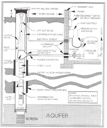
2020

microbial contamination is usually substantially greater in western than in eastern Kansas for the
same horizontal separation unless there is poor well construction. When the soil blanket is thin,
poorly- drained, shallow to rock, very coarse, or combinations of these conditions occur, more
rapid groundwater recharge rates are likely. The more quickly water moves through the soil to
groundwater, the greater the risk of microbes being carried to the aquifer. These conditions more
commonly occur in eastern Kansas, meaning that greater separation distances are needed to
provide the same measure of protection as in western Kansas. Additionally, groundwater
movement through joints, cracks, and solution channels of rock aquifers in eastern Kansas is
much more rapid. This also reduces the protection provided by horizontal separation.

PRIVATE WATER WELLS                                                                             I-5
2020

Table I-1. Public and Private Water Systems in Kansas
                                       UNITS WITH PUBLIC WATER    UNITS WITH PRIVATE
                                     SYSTEM OR PRIVATE COMPANY      WATER SUPPLIES
    County     Total Housing Units     Number          Percent   Number       Percent
      Allen            6,454             6,047           93.7      407           6.3
   Anderson            3,514             3,127           89.0      387          11.0
   Atchison            6,691            6,015            89.9      676          10.1
    Barber             3,120             2,452           78.6      668          21.4
    Barton            13,144            10,699           81.4     2,445         18.6
   Bourbon             6,920             6,490           93.8      430           6.2
     Brown             4,890             3,711           75.9     1,179         24.1
     Butler           20,072            15,937           79.4     4,135         20.6
     Chase             1,547              934            60.4      613          39.6
 Chautauqua            2,249             1,711           76.1      538          23.9
   Cherokee            9,428             8,390           89.0     1,038         11.0
  Cheyenne             1,687             1,104           65.5      583          34.5
     Clark             1,327              975            73.5      352          26.5
      Clay             4,138             3,331           80.5      807          19.5
     Cloud             5,198            4,371            84.1      827          15.9
     Coffey            3,712             3,166           85.3      546          14.7
  Comanche             1,256              889            70.8      367          29.2
    Cowley            15,569            14,012           90.0     1,557         10.0
   Crawford           16,526            16,311           98.7      215           1.3
    Decatur            2,063             1,369           66.4      694          33.6
   Dickinson           8,415             6,521           77.5     1,894         22.5
   Doniphan            3,337            2,582            77.4      755          22.6
   Douglas            31,782            30,574           96.2     1,208          3.8
   Edwards             1,867             1,381           74.0      486          26.0
       Elk             1,743             1,394           80.0      349          20.0
      Ellis           11,115             9,725           87.5     1,390         12.5
   Ellsworth           3,317             2,368           71.4      949          28.6
    Finney            11,696             9,543           81.6     2,153         18.4
      Ford            10,842             9,118           84.1     1,724         15.9
    Franklin           8,926             7,792           87.3     1,134         12.7
     Geary            11,952            11,007           92.1      945           7.9
     Gove              1,494              984            65.9      510          34.1
    Graham             1,753             1,153           65.8      600          34.2
     Grant             2,599             1,941           74.7      658          25.3
      Gray             2,114             1,401           66.3      713          33.7
    Greeley             801               511            63.8      290          36.2
  Greenwood            4,243             3,665           86.4      588          13.6
   Hamilton            1,214              942            77.6      272          22.4
    Harper             3,481             2,920           83.9      561          16.1
    Harvey            12,290            10,655           86.7     1,635         13.3
    Haskell            1,586            1,057            66.7      529          33.3
  Hodgeman             1,022              531            52.0      491          48.0
   Jackson             4,564             3,705           81.2      859          18.8
   Jefferson           6,314             5,335           84.5      979          15.5
     Jewell            2,409             1,845           76.6      564          23.4
   Johnson           144,155           143,434           99.5      721           0.5
    Kearny             1,561             1,145           73.4      416          26.6
   Kingman             3,645             2,219           60.9     1,426         39.1
     Kiowa             1,738             1,306           75.2      432          24.8
    Labette           10,641            10,204           95.9      437           4.1
      Lane             1,117              770            69.0      347          31.0
 Leavenworth          21,264            19,328           90.9     1,936          9.1
    Lincoln            1,864             1,258           67.5      606          32.5

PRIVATE WATER WELLS                                                                     I-6
2020
Table I-1. Public and Private Water Systems in Kansas (cont.)
UNITS WITH PUBLIC WATER UNITS WITH PRIVATE
SYSTEM / PRIVATE COMPANY WATER SUPPLIES
County Total Housing Units Number Percent Number Percent
Linn 4,811 4,209 87.5 602 12.5
Logan 1,466 1,090 74.4 376 25.6
Lyon 14,346 13,413 93.5 933 6.5
Marion 5,659 4,051 71.6 1,608 28.4
Marshall 5,269 4,394 83.4 875 16.6
McPherson 10,941 8,982 82.1 1,959 17.9
Meade 2,049 1,518 74.1 531 25.9
Miami 8,971 7,912 88.2 1,059 11.8
Mitchell 3,359 3,100 92.3 259 7.7
Montgomery 17,920 16,534 94.5 986 5.5
Morris 3,149 1,602 50.9 1,547 49.1
Morton 1,515 1,151 76.0 364 24.0
Nemaha 4,319 3,602 83.4 717 16.6
Neosho 7,726 7,362 95.3 364 4.7
Ness 2,048 1,464 71.5 584 28.5
Norton 2,798 2,048 73.2 750 26.8
Osage 6,324 5,843 92.4 481 7.6
Osborne 2,496 1,981 79.4 654 20.6
Ottawa 2,591 1,842 71.1 749 28.9
Pawnee 3,412 2,599 76.2 813 23.8
Phillips 3,264 2,421 74.2 843 25.8
Pottawatomie 6,472 4,756 73.5 1,716 26.5
Pratt 4,620 3,520 76.2 1,100 23.8
Rawlins 1,744 994 57.0 750 43.0
Reno 26,607 19,981 75.1 6,626 24.9
Republic 3,283 2,652 80.8 631 19.2
Rice 4,868 3,748 77.0 1,120 23.0
Riley 22,868 20,695 90.5 2,173 9.5
Rooks 2,979 2,356 79.1 623 20.9
Rush 1,999 1,525 76.3 474 23.7
Russell 4,079 3,789 92.9 290 7.1
Saline 21,129 20,114 95.2 1,015 4.8
Scott 2,305 1,701 73.8 604 26.2
Sedgwick 170,159 155,355 91.3 14,804 8.7
Seward 7,572 6,875 90.8 697 9.2
Shawnee 68,991 67,749 98.2 1,242 1.8
Sheridan 1,324 752 56.8 572 43.2
Sherman 3,177 2,532 79.7 645 20.3
Smith 2,615 1,903 72.8 712 27.2
Stafford 2,666 1,583 59.4 1,083 40.6
Stanton 956 634 66.4 322 33.6
Stevens 2,116 1,606 75.9 510 24.1
Sumner 10,769 8,410 78.1 2,359 21.9
Thomas 3,534 2,611 73.9 923 26.1
Trego 1,851 1,258 68.0 593 32.0
Wabaunsee 2,853 1,640 57.5 1,213 42.5
Wallace 840 566 67.4 274 32.6
Washington 3,355 2,449 73.0 906 27.0
Wichita 1,190 767 64.5 423 35.5
Wilson 5,091 4,592 90.2 499 9.8
Woodson 2,199 1,794 81.6 405 18.4
Wyandotte 69,102 68,825 99.6 277 0.4
State Totals 1,044,112 934,205 89.5 109,656 10.5
Source: US Census Bureau 1990 Housing Census
PRIVATE WATER WELLS I-72020
Minimum separation distances regulated by K.A.R. 28-30-8 and K.A.R. 28-5-2 are presented in
Table I-2. The plan view in Figure I-1 shows the well location as well as the required and
recommended separation distances from sources of contamination. These distances should be
adequate to protect from microorganism contamination, however greater distances provide added
protection. Much greater separation distances are necessary to protect from other pollution
sources (inorganic and organic chemicals).
A sanitarian, extension agent or other qualified person should be called upon to assist in siting a
new well location. A protocol to evaluate a new well site or existing well and a report form to
assist in collecting the necessary data is included at the end of this chapter.
TABLE I-2. Minimum and Recommended Separation Distances from Private
Wells
POTENTIAL SOURCE OF POLLUTION SEPARATION DISTANCES
(in feet)
Min. Required1 Recommended2
Sealed sewer line (cast iron, tight line, etc.) 10 50
Unsealed sewer lines 50 > 400
Septic tanks (watertight) 50 > 100
Lateral lines and septic absorption field 50 > 400
Pit privies 50 > 400
Stables, livestock pens, lagoons and manure piles 50 > 400
Streams, lakes and ponds 50 > 100
Fertilizer and fuel storage (above or below ground) 50 > 400
Seepage pits (prohibited after May, 1996) 50 > 400
All other wastewater systems 50 > 100
Property line 25 > 50
Public water supply sources (i. e., wells) 3 100 > 100
Building/structure (termite treatment) 4 50 > 100
Pesticide storage, mixing and disposal repeated use areas 50 > 400
1
Required by K.A.R. 28-30-8.
2
Separation distances that help assure more adequate protection from contaminants other than bacteria.
3
From Policies, General Consideration and Design Requirements for Public Water Supply Systems in Kansas.
4
Required when injecting liquid pesticide, see manufacturers label. These distances do not assure
contamination will not reach well
PRIVATE WATER WELLS I-82020 Figure I-1. Site Features Showing Minimum and Recommended Separation Distances PRIVATE WATER WELLS I-9
2020

Protection from Other Contaminants
Protecting wells from contaminants other than microorganisms involves management at the
surface and separation distances greater than 50 feet. The Farmstead Well Study, conducted by
the Kansas State University and Kansas Department of Health and Environment in 1986-87,
found 28 percent of the wells with nitrate levels above the safe drinking water standard of 10
mg/L. Other inorganic chemicals above the standard were found in an additional 10 percent of
wells. Pesticides were detected in 8 percent of the wells but were above the EPA drinking water
standard in only 1 percent of wells.

Protection of well water from sources of contamination other than microorganisms requires
much more careful planning. For instance, nitrate, like most negatively charged inorganic
constituents (known as anions) moves freely through the soil. It is dissolved in water and is
carried along as the water percolates through the soil to the groundwater and moves in the
aquifer. The most active removal mechanisms for nitrate are: a) careful management of nitrogen
sources at the surface, b) removal by plants as water percolates through the root zone, and c)
denitrification in shallow, poorly aerated layers. Once nitrate reaches groundwater, there is
virtually no mechanism for removal except lateral movement with groundwater to a well or
reappearance at the surface through springs.

Some organic and inorganic chemicals, both natural and man-made, are adsorbed by the
exchange capacity of clay and organic matter in the soil. However, excessive repeated
applications, dumping, and spills can exceed the soil’s capacity to remove these contaminants.
Because most organics are at least partly dissolved in water, if they are not removed they can be
carried to groundwater.

The effluent from a properly designed and operated wastewater system still contains large
amounts of dissolved nutrients, some of which eventually may reach groundwater. The effluent
also contains some chemical contaminants and viruses which are capable of traveling long
distances when they reach groundwater, especially in jointed and channeled rock. The required
minimum separation distance for wastewater systems is 50 feet from private water supplies and
100 feet from public water supplies. However, to minimize possible health hazards and pollution
potential of wastewater systems it is good policy to locate them as far as possible from drinking
water supplies and surface water.

The type and number of wastewater systems and other sources of pollution in the vicinity of a
well gives an indication of the potential for contamination of the groundwater supplying that
well. The well construction, volume of water pumped, and the well draw-down are also
extremely important as they determine the distance and speed with which pollution may travel.
Usually pollution will be minimized with increased separation distance and groundwater travel
time.

Cone of Depression
A well in regular use causes groundwater to flow towards the pumping well. The withdrawal of
water from the well by pumping causes the water level in the well to be lower than the static,
nonpumping, water table. This lowers the pressure (creates a vacuum) in the area surrounding the
well which in turn causes the groundwater level to decline around the well. This drop in the level

PRIVATE WATER WELLS                                                                           I-10
2020

of the water table around the well is called the cone of depression. The distance away from the
well that the cone of depression extends is the radius of influence. Any source of contamination
that reaches the groundwater within the radius of influence can be drawn toward the well. See
diagram of cone of depression for a pumping well in Figure I-2.

Figure I-2. Cone of Depression for a Pumping Well

Example of cone of depression. The elevation at the well is 1,200 feet, the original water table is
1,080 feet, the water level is 1,050 feet when the well is pumped, and the radius of influence is
400 feet. A pollution source located 350 feet from the well can potentially contaminate the well
if the contamination moves down to groundwater, elevation about 1,078 feet, within the cone of
depression. Thus, the protection of a well from pollution sources is not just a matter of surface
separation distance. Rather it is a combination of surface separation, elevation of the pollution
sources and well, radius of influence (cone of depression) of the pumping well, and groundwater
flow direction and gradient.

Wells, in areas of fractured limestone formations near the ground surface or where solution
channels are known to exist in the rock formations, should be separated by much greater
distances from pollution sources. Special precautions should be taken to prevent shallow
subsurface seepage from entering the well. The surface ground slope should be away from the
well. Local sanitary and environmental codes may require more stringent standards than state
regulations and should always be consulted before sitting a new well.

When factors that might influence well contamination were evaluated in Phase 2 of the
Farmstead Well Study, separation distance was the strongest contributor to contamination. The
greater the distance of the source of contamination from the well, the less chance there is of
contamination affecting water produced by the well. Based on this study, a minimum 200 foot

PRIVATE WATER WELLS                                                                             I-11
2020

separation distance from sources of contamination is recommended to provide adequate
protection of wells for both inorganic and organic contaminants

Locating a New Well
Careful evaluation of all potential sources of contamination is essential when siting the location
of a well. Many potential sources are shown in Figure I-1 for a modern farmstead.
Contamination sources include fertilizer and pesticide handling, storage, mixing and clean-up
areas; above and below ground fuel storage tanks; and mechanic/maintenance shop areas where
solvents and degreasers are used.

A good approach to safely locate a well is to draw a 200 foot radius circle around each of the
potential sources of contamination and then locate the well outside of all circles. Be sure the well
is located up-gradient in groundwater flow direction from these sources. Figure I-3 illustrates a
typical rural development with the preferred location of pollution sources associated with house,
yard, and septic system in relation to the location of the well.

A study during 1994-1995 sponsored by the Centers for Disease Control found total coliform
bacteria present in 51 percent of private drinking water wells in Kansas. E. coli was present in 18
percent of these wells. Approximately 80 percent of the wells included in this study did not meet
either location guidelines or current construction standards.

See Protocol: Well Evaluation for a New Site or Existing Private Well at the end of this chapter.

WELL CONSTRUCTION
To supply good water, the well construction must prevent the entrance of all surface water and
shallow or deep groundwater seepage into the well except at screened sections. Approved grout
must restore the seal around the casing at the surface and through all confining layers.

The Kansas Groundwater Exploration and Protection Act, also called the Water Well
Construction Act, K.S.A. 82a-1201 et seq., and the implemented regulations, K.A.R. 28-30-1 et
seq., specify how wells are to be constructed, reconstructed, and plugged. They set minimum
standards for well construction and reconstruction, and specify materials used in constructing or
reconstructing water wells.

Well construction and reconstruction requires a licensed Kansas Water Well Contractor.

However, landowners may construct new wells, modify existing wells, and plug wells located on
their own property without being licensed by KDHE. Landowners must comply with all
requirements of the law and regulations including the filing of a Water Well Record (form
WWC-5) with KDHE as mandated by law.

Numerous methods have been developed for construction of water wells. These include digging,
driving, boring, and drilling. In recent decades, practically all new wells in Kansas are drilled or
driven. Recommendations and requirements for using these two methods as well as procedures
for reconstructing or upgrading dug wells are briefly discussed here.

PRIVATE WATER WELLS                                                                              I-12
2020

Figure I-3. Good Well Location and Separation Distances for a Farmstead

Wastewater flow for sizing a lagoon is based on average flow rather than peak flow, which is
used for sizing an inground wastewater system. Lagoons easily handle temporary high flows
with a rise in water level which results in an increase in losses. Conversely, inground systems
must be able to handle these peak flows to avoid a malfunction or failure.

PRIVATE WATER WELLS                                                                               I-13
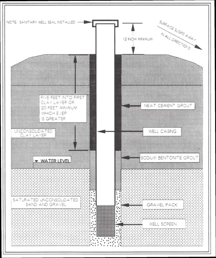
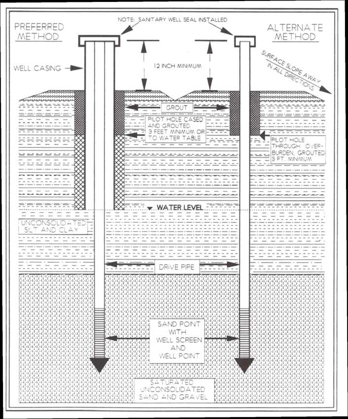
2020

Drilled Wells
A drilled well is constructed with a drilling machine using rotary, percussion, or jetting tools.
The hole is drilled into or through the water-bearing formation(s) and a casing and screen are
inserted into the bore hole. New PVC, wrought iron, steel or other KDHE approved materials, in
clean and serviceable condition, shall be used to case the well.

Construction details for unconsolidated (sand and gravel) and consolidated (rock) drilled wells
are shown in Figures I-4 and I-5. For purposes of illustration different grout materials are shown.

Driven Wells
Driven well construction is limited to areas of unconsolidated aquifers and where the water-
bearing strata lie at comparatively shallow depths. Driven wells are most often used only where
the water table is less than 20 feet below ground surface. Driven wells can not be used where
there are intervening formations of rock, hard and dense layers, or boulders that would interfere
with the driving of the pipe.

Driven wells are properly constructed by drilling and casing at least the upper 10 feet of the well
or to the water table if more than 10 feet. This provides for easy placement of the required
protective grout around the outer casing placed in the bore hole. The outer well casing must meet
the casing requirements of K.A.R. 28-30-1, et seq. The well is completed by driving a water-tight
pipe (normally steel) that is fitted with a drive point and a well screen into the water-bearing
formation below the water table to the desired depth, sufficient for continuous pumping.

Construction details for a driven well are shown in Figure I-6

Dug Wells
Construction of dug wells has been illegal since the Well Construction Act was passed in 1975.
Existing dug wells should be abandoned and properly plugged or reconstructed to meet the
requirements of this act and accompanying regulations. Reconstruction of dug wells to meet
current well construction standards and thus reduce potential of contamination is generally not
cost effective.

Well Casing
To insure adequate protection of the aquifer(s) supplying the well, the casing must exclude
surface water and water from undesirable subsurface strata. All wells must have durable,
watertight casing from at least one foot above finished ground surface (recommend at least one
foot above the elevation of the 100-year flood) to the top of the producing zone(s) of the aquifer.
The watertight casing shall extend at least at least 5 feet into the first clay or shale layer or a
minimum of 20 feet below the finished ground surface. The casing shall be clean and serviceable
and of a type to assure that it remains watertight for the useful life of the well (usually at least 40
years). Used, reclaimed, rejected, or contaminated pipe shall not be used for casing any well.

Groundwater producing zones that are known or suspected to contain natural or man-made
pollutants must also be cased and sealed off during construction of the well to prevent the
movement of the polluted or undesirable groundwater to either overlying or underlying fresh
groundwater zones.

PRIVATE WATER WELLS                                                                                I-14
2020

Figure I-4. Construction of A Drilled Well in an Unconsolidated Formation

PRIVATE WATER WELLS                                                     I-15
2020

Figure I-5. Construction of A Drilled Well in a Consolidated Rock Formation

PRIVATE WATER WELLS                                                     I-16
2020

Figure I-6. Construction of A Driven Well

PRIVATE WATER WELLS                         I-17
2020

All water well casing must be approved by KDHE. Plastic pipe must meet standards of the
National Sanitation Foundation (NSF) or American Society for Testing and Materials (ASTM)
and bear the stamp of approval PW (potable water), DW (drinking water) or WELL CASING. It
is important that all connections (joints) be watertight where two sections of well casing are
joined. Concrete pipe, vitrified clay tile, and similar type materials are not approved for well
casing unless special permission is granted by KDHE as provided in the Appeals Clause in
K.A.R. 28-30-9.

The casing must be of sufficient inside diameter (ID) to easily accommodate the maximum
outside diameter (OD) of the pumping equipment to be installed in the well. Most small drilled
wells serving farmsteads, homes, and businesses are cased with five-inch ID casing or larger.

Casing of this diameter will accommodate most submersible turbine pumps, deep well jet pumps,
reciprocating pumps, and numerous other types of shallow well pumps in sizes commonly used
to supply water for household purposes.

The well casing must be watertight from the screened intake to at least twelve inches above
finished ground surface. No casing shall be cut off below the ground surface except to install a
pitless well unit. No holes shall penetrate the watertight well casing except to install a pitless
adapter and this penetration must be finished watertight.

Well Grouting
The space between the casing and the bore hole must be grouted to restore aquifer separation by
preventing water movement through this space. The diameter of the bore hole must be at least
three inches greater than the maximum outside diameter of the well casing to facilitate the
placement of grout around the casing throughout the required intervals. Adequately grouted
wells protect the well and aquifer from contamination by preventing the mixing of surface water
or water from different aquifer layers through the bore hole.

All well casing must be grouted to a depth of 20 feet or more below the finished ground surface.
When the first clay or shale layer is deeper than 20 feet from ground surface, then the grouted
interval must extend at least five feet into the clay or shale layer. The grouting requirement may
be modified to meet local conditions (i.e. groundwater is encountered at less than the 20-foot
minimum depth) when prior approval is obtained from KDHE.

For example, while drilling the bore hole a clay layer is found at 34 feet below the ground
surface. At 57 feet the clay layer changes to sand and gravel that contains potable groundwater.
The placement of the well casing would be then from the top of the aquifer (57 feet) to at least
one foot above finished ground surface. The well casing is grouted into the bore hole from the
34-foot depth to finished ground surface or to a depth just below the deepest frost line if a pitless
adapter or pitless unit is installed. The construction of a concrete slab around the well casing is
optional and may also help provide a good seal around the casing in addition to providing a
strong clean work platform for servicing the well.

It is common for wells that penetrate multiple water bearing layers to be designed to obtain
groundwater from two or more separate aquifers. In such wells, the casing interval between the
aquifers must be grouted into the bore hole to maintain aquifer separation within the borehole

PRIVATE WATER WELLS                                                                               I-18
2020

even though two or more aquifers are communicating through the well’s screens. This
requirement is mandated to assure that if one of the aquifers becomes unusable it can be blocked
off from the other aquifer with packers or sealed off with a blank casing liner or abandoned and
plugged to protect the usable aquifer from the undesirable aquifer.

Well Screen and Gravel Pack
The well screen should be factory slotted and installed as designed to prevent gavel pack or
aquifer materials from entering the well. Well screens should be made of corrosion-resistant
materials. In most cases, screens that are fabricated from an alloy of copper, tin, silicon, and
manganese are satisfactory. In waters containing large amounts of sulfate or detectable hydrogen
sulfide, a stainless steel or polyvinyl chloride (PVC) plastic screen should be used to enhance
corrosion protection. The choice of the well screen slot size (mesh size) is dependent on the
particle size of the aquifer material and the gravel pack used. By examining samples of the
aquifer materials collected when the well is drilled, most well screen manufacturers can
determine the screen slot size and gravel pack design needed to prevent fines from entering.

Fine, silty sand cannot normally be prevented from entering the well by use of a well screen
alone. In this case, a specific gravel pack design is critical to control the continuing entrance of
fines into the well. Washed, graded gravel pack disinfected with at least 200 parts per million
(ppm) chlorine solution is placed around the well screen to prevent entrance of undesirable fine
material. This chlorine concentration is produced by 51 ounces of 5¼ percent chlorine bleach, 27
ounces of 10 percent liquid chlorine bleach, or 4 ounces of dry 65 percent dry chlorine per 100
gallons of water.

When the aquifer contains large quantities of fine material such as very fine sand or silt, in
addition to good well screen and gravel pack design, thorough development of the well is
essential. Development helps retard the movement of very fine sand and silt into the well. Sand
and silt accelerate wear on the pump and can accumulate in the bottom of the well which may
prevent proper cooling of the pump motor and eventual motor failure. Sediment can accumulate
in plumbing, pressure tank, and water heater and also cause turbidity in the water.

Well Development
Well development is a specialized part of well construction and should be done by a Kansas
Licensed Water Well Contractor who has the necessary equipment. It is recommended that all
newly constructed or reconstructed wells be developed by one of the procedures discussed here.
Think of development as dislodging and washing fine material out of the aquifer adjacent to the
well. Some of these fines are introduced during well drilling.

Well development is accomplished by using a bailer, high pressure jetting, over-pumping (a rate
exceeding the well capacity to deliver water), and other methods that physically force the well
water back and forth through the well screen and gravel pack. The action of water moving in and
out of the well screen, gravel pack, and adjacent aquifer removes the majority of the very fine
sand and silt in the aquifer within the immediate vicinity of the well bore. The larger particles of
the aquifer are left in place, next to the gravel pack, which effectively helps hold back the very
fine sand and silt that is farther away from the gravel pack.

PRIVATE WATER WELLS                                                                             I-19
2020

A bailer (a hollow open top cylinder pipe from 5 to 20 feet long with an opening and flapper
valve in the bottom) is lowered into the well. The flapper valve opens when the bailer is lowered
into the well and then close when it reaches the bottom. Repeatedly lowering and raising the
bailer surges the well, pushes and pulls water in and out of the well screen, gravel pack, and
adjacent aquifer. The very fine sand and silt is dislodged, suspended, and flushed into the casing.
The bailer is drawn to the surface with flapper valve closed and its contents, water with
sediment, is discharged to waste. Well development by bailing is continued until the water
withdrawn is mostly clear of sediment.

The over-pumping development method involves placing a high capacity pump (without the
normal check valve) and pump column pipe near the bottom of the well. When the pump is
turned on, the water is lifted and discharged at the surface to waste. After the pump has been
discharged for a period of time, it is turned off and the water inside the pump column is forced
by gravity into the well and back through screen. This washes or “back-flushes” the fine
materials from around the well screen. This cycle is repeated many times, with the length of the
discharge time increased each time. Pumping continues until the water discharged to waste is
clear.

High pressure jetting development involves using a tool with nozzles that drives high pressure
water into the screen while the tool is lowered, raised, and rotated throughout the well screen
area. Water that meets drinking water standards and that has been disinfected is delivered by
pump to the nozzle jets. After jetting, the tool is removed and a bailer or pump is used to remove
the dislodged sediments. Alternate jetting followed by sediment removal is repeated in sequence
until the well water becomes clear.

Sanitary Well Seal
The top of every well casing must be fitted with a KDHE approved, water-tight sanitary seal to
prevent entry of contaminants including water, animals, insects, or other pollutants. If the pump
is not installed immediately, a permanent cap can be installed on the casing. This seal or cap
prevents any contamination from accidentally entering the well and minimizes chances of
vandalism. The sanitary seal is available for use with a variety of pumps, piping, and well casing
diameters. Examples are illustrated in Figure I-7.

See Protocol: Well Evaluation for a New Site or Existing Private Well at the end of this chapter.

DISINFECTION OF WELL
The well casing, pump, wiring, and piping system should be thoroughly disinfected following
well construction, development, repairs, pump installation, and annually as part of a
preventive maintenance program.

When wells are constructed or reconstructed and pumps and piping are installed or repaired,
microbiological contamination often results. All wells used for human consumption or food
processing must be thoroughly disinfected before its first use in compliance with K.A.R. 28-30-
10. An effective and economical method for disinfecting water wells is through the use of a high
strength chlorine solution. Common laundry bleach contains a 5¼ or 6 percent solution of
sodium hypochlorite is readily available and suitable to make the chlorine solution.

PRIVATE WATER WELLS                                                                            I-20
2020

The recommended chlorine dosage for disinfection of existing wells, reconstructed wells, pump
replacement or pump or well repairs is 500 mg/L or ppm (a gallon of laundry bleach for each 100
gallons of water) in the well and plumbing system. For disinfection of new wells, a dosage of
100 mg/L or ppm (one gallon of laundry bleach for each 500 gallons of water) is recommended.
The recommended procedure for disinfecting water wells is found in Appendix A and in K-State
Research and Extension publication Shock Chlorination for Private Water Systems, MF-911.

Following disinfection of the well and its appurtenances (plumbing), a sample of water should be
collected after 7 days for bacteriological analysis. Prior to sampling the water, a test for free
chlorine should be made. If chlorine is present, bacterial analysis should be postponed until the
water is free of chlorine. If the bacteriological analysis indicates the water is still contaminated,
the disinfection procedure should be repeated.

In rare cases, after careful investigation fails to reveal any defects in location or construction of
the well and total coliform bacteria continue to be present, installation of equipment that
provides continuous disinfection many be necessary.

Note: continuous disinfection is not a reliable replacement for proper well location and
construction.

PRIVATE WATER WELLS                                                                                I-21
2020

Figure I-7. Sanitary Well Seals

PRIVATE WATER WELLS               I-22
2020

WELL PUMPS
The well should be provided with a pump selected for the application. The pressure and volume
relationship that defines the pump curve is the primary factor in choosing the correct pump for
the application. The pump should be installed in a manner that will prevent contamination from
entering the well. A wide variety of pump equipment is available for lifting and pressurizing
water from wells. The two most common devices, power pumps and hand pumps, are discussed
in the following sections:

Power Pumps
Two types of power pumping equipment are commonly installed today on private water supply
wells; the submersible turbine type pump and the jet type pump. Examples of power pump
equipment and the important sanitary features governing their installation are shown in Figures I-
8 and I-9. For more information on pumps refer to the EPA Manual of Individual and Non-
Public Water Supply Systems or the Midwest Plan Service Private Water Systems Handbook.
See references for complete citations.

PRIVATE WATER WELLS                                                                           I-23
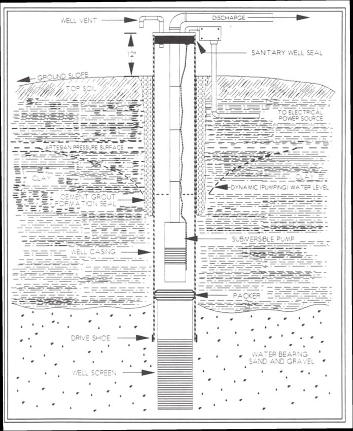
2020

Figure I-8. Submersible Pump Components

PRIVATE WATER WELLS                       I-24
2020

Figure I-9. Twin Tube Jet Pump Components for Deep Well

PRIVATE WATER WELLS                                       I-25
2020

Figure I-10. Sanitary Hand Pump Components

Hand Pumps
The basic sanitary requirements for hand pumps are:

   1) A solid, one piece, recessed type cast iron pump base, cast or threaded to the pump
      column, must be provided.

   2) The top of the pump must be provided with a stuffing box or gland that forms a seal for
      the pump sucker rod.

   3) The pump spout must be closed and directed downward.

   4) A flange and gasket must be provided for attaching the pump base to the well casing.

PRIVATE WATER WELLS                                                                          I-26
2020
5) The pump cylinder should be located below the static water level in the well so that
priming of the pump is not necessary.
6) Adequate overhead clearance is essential to permit removal of pump rods, pump column
pipe and pump cylinder for maintenance, repairs or replacement.
The recommended design for a hand pump installation is shown in Figure I-10.
FREEZE PROTECTION
Well installations require freeze protection for the piping and in some cases also the pump and
pressure tank. Two feasible freeze protection options are pitless installations with the pump
located in an area not subject to freezing, such as a basement or well pit at least 2 feet from the
well, or an insulated pump house with supplemental heat. A submersible pump installed in the
well is the most common pump type except for shallow wells. In the past, wells were often put in
pits, basements, garages, and crawl spaces, or buried beneath the ground surface for freeze
protection. These techniques and locations are all prohibited by state regulation K.A.R. 28-30-
6(o) implemented in 1975 because of the high potential for contamination.
Well Pump House
A pump house is a structure built over well on a concrete floor to protect equipment from
freezing and damage. The size of the pump house depends on how much equipment, the size of
the equipment and how much space is needed to remove, replace or repair the equipment placed
there. Allow adequate room to work comfortably while repairing or replacing. If you plan to
install a pump, pressure tank, and disinfection equipment, the building will need to be larger than
if only the pump will be housed there. Dimensions of a small pump house would be four feet
long by four feet wide by seven feet tall. A larger pump house could be eight feet wide by eight
feet long by seven feet tall. The roof should always be built so it can easily be removed or have a
hatch that can be opened to enable removal of the pump column. The complete structure should
be watertight, vermin and insect proof, and insulated to retain heat in the winter. A well work-
over pulling unit is often used to pull pump rods, pump column pipe, submersible pumps, and
other lengthy equipment placed inside the well.
In order to install as much insulation as practical, R30 if possible, the walls and ceiling should be
10 inches thick for fiberglass and 5½ inches thick for rigid foam. All walls should be solid on the
interior and exterior and trimmed or sealed where they meet. All vents should be fine mesh
screened to reduce the likelihood of insect entry. The door should be well insulated, weather
stripped, and lockable. The pump house floor should be constructed of reinforced concrete at
least four inches thick and sloped away in all directions from the well casing or suction pipe.
Because the danger of electrical shock is greater with a wet floor, care should be exercised when
installing electrical equipment in the pump house to be sure that the floor is well-drained and
dry.
Supplemental heat can be provided by installing a thermostatically controlled heater, usually
electric heat tape near the floor around piping, or an alternate heat source. A ground fault circuit
interrupter (GFCI) should be used for all circuits in areas of water. All electrical wiring should
be placed in vermin proof conduit.
PRIVATE WATER WELLS I-272020 Continuous chlorination of private well supplies is not normally required but provisions for installation of such equipment should be included in the pump house design. Figure I-11 shows recommended construction for the pump house. The pump house should not be used to store any material that could contaminate water including pesticides, paint, products that contain petrochemicals, or other chemicals or products. Pitless Installations Figure I-12 illustrates a typical pitless well device installation. The device (called a pitless well adapter or pitless unit) is often used in conjunction with a submersible pump to assure freeze protection for water lines. A basement may be a suitable option for locating the pump and pressure tank. A 50-foot separation distance of the well from buildings is required because of potential contamination from termite treatment. This separation of the well applies when the pump and pressure tank are located in the basement. The design of a pitless well unit and a pitless well adapter are shown in Figure I-13. A well in a pit has been illegal for new construction since the Well Construction Act was adopted in 1975. A pump pit can still be used but must be located at least 2 feet away from the water well. PRIVATE WATER WELLS I-28
2020

Figure I-11. Typical Pump House Components

PRIVATE WATER WELLS                          I-29
2020

Figure I-12. Typical Pitless Well Device

PRIVATE WATER WELLS                        I-30
2020

Figure I-13. Design of Typical Pitless Unit and Pitless Adapter

WELL MAINTENANCE
The first concern is always that the location meets recommended separation distances between
the well and sources of contamination as shown in Table I-2. Location is the most important
factor for protection of water quality. Second is the quality of well construction which is of
concern primarily when the well is initially drilled. However, well components deteriorate over
time, can be damaged, or may be removed and not correctly reinstalled that means the well may

PRIVATE WATER WELLS                                                                         I-31
2020

no longer meet the construction standards and thus would be unsafe. Well maintenance is the
important action needed to help assure that wells continue to be safe for supplying safe water.

In addition to good well location and construction that meets current well standards, regular
maintenance helps ensure that the well continues to be a safe source of drinking water. A well
that is not maintained can not be expected to reliably produce safe water. Recommended annual
well maintenance includes: checking the well casing for leaks, checking for a secure and
watertight well seal, assuring that the ground surface slopes away from the well, disinfection of
the well and water system, and a verifying water test is free of coliform bacteria. A checklist,
recommended for an annual well maintenance procedure is presented in Table I-3. Note: See
Extension bulletins in references at the end of the chapter for additional information

Table I-3. Private Well 12-Point Maintenance Check

Do each year:

   •   Check that the well casing is free of cracks or other leaks from the water table to at least
       1 foot above the ground surface or highest flood level whichever is greater.
   •   Check that the sanitary seal is a KDHE-approved type and is secure and watertight.
   •   Make sure the ground slopes away from the well for at least 15 feet in all directions.
   •   Shock chlorinate the well and water system.
   •   Test coliform bacteria, nitrate, pH, and total dissolved solids and file the results with
       other records and information about the well.

Always do:

   •   Have a licensed water well contractor do all work on the well and casing and be sure
       well meets all current KDHE minimum construction standards.
   •   Find and fix the cause of any change in water color, odor, or taste. Disinfect the well and
       water system following any service on the system.
   •   Maintain 50 ft. (100 ft. preferred) of open space between the well and any buildings, waste
       system, parked vehicle, equipment, compost, or other possible contamination source.
   •   Store chemicals such as fertilizer, pesticides, oil, fuel or paint at least 100 ft. down
       slope.
   •   Prevent backflow and backsiphonage by maintaining an air gap above the container you
       are filling, or by using an adequate backflow prevention device.
   •   Disinfect the well after any service work on the pump, well, or water system.
   •   Plug all abandoned wells and wells not used in the last 2 years following state
       regulations or upgrade them to current standards. Plug all unused cesspools, septic
       tanks, and other holes.

Finally, every well needs a wellhead protection plan to assure continuing protection of water
quality, especially for those wells being used for drinking water. The wellhead protection plan
indicates site vulnerability to groundwater contamination and rates the risk of activities within
500 feet of the well. For the plan to have any benefit, it must be followed and updated by the
landowner or user. With many problems of poor private well water quality in Kansas, it is in the
owners’ interest to take steps to protect their own wells so they can have safe water.

PRIVATE WATER WELLS                                                                               I-32
2020 Water Testing Remember: No Federal or Kansas law regulates the quality of drinking water from private water supplies. The owner or user is responsible for the quality of water from a private well. After the annual maintenance check is done, a water test is recommended for coliform bacteria, nitrate, pH, and total dissolved solids concentration. Water testing confirms the water safety after all efforts have been made to be sure the well is safe. When coliform bacteria is used as an indicator of safe drinking water, a monthly test is recommended (a minimum is a quarterly, 4 per year, test). Frequent testing can assist in identifying problems and alerting the need for action. Additional testing is advised following an event which could jeopardize water safety, such as: • Flooding or spills that could cause contamination • Any evidence that water quality may have changed (taste, odor, color, turbidity, etc.) • Frequent or unexplained illness of people or animals • Poor livestock or animal performance (weight gain, litter size, mortality, health) The choice of which test(s) to perform will be a judgment based on each situation. If potential contamination conditions are present near the well (i.e., landfill, chemical storage/handling, or fuel storage) it would be advisable to test more frequently and for a wider range of potential contaminants such as pesticides, synthetic organic chemicals, volatile organic chemicals, and radionuclides. See the K-State Research & Extension publication Recommended Water Tests for Private Wells, MF-871, for information on what to test for and how often. Previously untested wells should be tested for basic water chemistry. This includes evaluation for the most common minerals and nuisance contaminants. Except in cases of gross contamination or a catastrophic event, basic chemistry usually changes slowly so re-testing every three to five years is adequate. A basic water chemistry test usually includes common cations (calcium, magnesium, sodium, iron, manganese) and anions (chloride, carbonate, bicarbonate, sulfate, nitrate). Testing should be based upon past, present, and future site uses as well as groundwater quality data. It is advisable to contact a KDHE certified laboratory for specific sampling procedures, sample bottles, and the best time to collect and submit samples. K-State Research & Extension publications provide background information on recommended water tests and sample collection. See Appendix B for a brief description of the standards and significance for common inorganic chemicals. See Appendix C for Homeowner/User Water Quality Screening Results Interpretation and Recommended Corrective Actions For Wells. Drinking Water Standards Kansas’ regulation of drinking water is authorized by state law, K.S.A. 65-171m. Primary drinking water regulations are outlined in K.A.R. 28-15a-1 through K.A.R. 28-15a-571. Kansas regulations adopt the US EPA Safe Drinking Water Standards by reference. PRIVATE WATER WELLS I-33
2020

Drinking water standards are separated into two broad groups: primary standards or maximum
contaminant levels (MCL), and secondary standards or secondary maximum contaminant levels
(SMCL). Primary standards are established for substances which may produce adverse health
effects (i.e., bacteria, heavy metals, other inorganic chemicals, and organic compounds). Public
water supplies must not exceed the primary standards or regulations. A brief discussion of
common inorganic drinking water contaminants is included in Appendix B.

In the absence of standards or guidelines for private water supplies, public water supply
standards are recommended. K-State Research and Extension publications Understanding Your
Water Test Report, MF-912 and Organic Chemicals and Radionuclides in Drinking Water, MF-
1142 lists standards for inorganic and organic contaminants (see references).

Secondary standards are established for aesthetic purposes (taste, odor, appearance, etc.) and
certain non-aesthetic effects. EPA recommends secondary standards to the states as reasonable
goals. Secondary standards are not enforced by EPA or Kansas laws or regulations.

PROTECTION OF WELLS (WELLHEAD PROTECTION)
Without a well protection plan, there is an increase chance of groundwater contamination
from activities near the well. Resultant effects are usually long term or permanent.

Wellhead protection is important because in addition to location and construction management of
activities near the well may affect the groundwater or aquifer supplying the well. Groundwater
does not recognize property boundaries and may extend hundreds or even thousands of feet from
the well site, especially up-gradient in groundwater flow. Protection offered by the soil is
missing whenever it is missing or penetrated by abandoned wells, rock quarries, gravel
operations, test holes, or other holes. The well’s water quality depends on protection and nearby
surface activities.

Potential contamination can be decreased or increased by location of the well. Generally, it is
best to locate wells as far as practical from sources of contamination, both biological and
chemical. Wells located up gradient in groundwater flow direction (usually up-slope on the
surface), have a reduced risk of contamination from nearby sources. Surface water should be
redirected by installing a diversion, a sloping channel with an integral ridge below, so water does
not flow near the well.

The effects of surface activities many times are not immediately obvious, but may have long
term consequences. Surface activities that can affect groundwater include application of fertilizer
and pesticide, confined animal feeding operations, fuel storage, and failure to provide adequate
backflow protection on the plumbing system. It is a fact that excessive fertilization of lawns and
crops as well as spills near a well can contribute to an increase in nitrate concentration in the
groundwater. Spills that occur while loading and mixing pesticides as well as the practice of
flushing containers or equipment onto the ground near a well can contaminate it.

The best protection for private wells from contamination occurs when a wellhead protection plan
exists in writing, is followed, and is reviewed regularly. The River Friendly Farm Plan –
Environmental Assessment Tool and Kansas Home•A•Syst, An Environmental Risk Management
Guide for the Home materials are available and may help in preparing the plan. First, potential

PRIVATE WATER WELLS                                                                            I-34
2020

sources of contamination are identified and their relative risk quantified. Then the highest risks,
together with actions to reduce these risks are summarized. Finally, the owner acts to correct the
highest risks first, then the next highest risks until all risks are reduced to low risks.

A good wellhead protection plan involves careful planning and should include a primary and
secondary protection area or zone as shown in Figure I-1. In the primary protection zone all
high-risk activities and conditions are prevented and moderate risk activities include measures or
management to reduce them to low risks. The radius for the primary protection zone should be a
minimum of 100 feet with up to 300 feet or more recommended.

In the secondary protection area or zone, high risk activities or situations employ additions or
management to shift them to low or moderate risks. Moderate risk activities include measures of
management to shift them to low risks. The radius for the secondary protection area should be a
minimum of 200 feet with 400 feet or more preferred. Guidelines for high, moderate, and low risks are
shown in Table I-4.

Table I-4. Relative Contamination Risks for Home and Farmstead Activities

Group A: High Risk

•   Polluting liquids without secondary containment such as fuel, solvents, chemicals (fertilizer,
    pesticide, etc.)
•   Liquid waste (sewage, manure, etc.)
•   Water-soluble materials like fertilizer, pesticides
•   Livestock lots, abandoned livestock lots and other wastes
•   Buildings and areas where the above materials are used, transferred, mixed, stored or
    cleaned up (such as: shop or sprayer fill/clean up area)
•   No backflow prevention for the water system

Moderate Risk

•   Intensive cropland especially irrigated land where chemicals (fertilizer or pesticide) are
    applied, gardens, home and yard
•   Powered equipment storage (tractors, truck, auto, etc.),
•   Garage, grain storage, silo
•   Livestock buildings with minimum liquids

Low Risk

•   Pasture rangeland, woodland, low intensity (low or no chemical) cropland
•   Nonpowered machine storage
•   Windbreak
•   Low use buildings
•   Organic garden, organic cropland
•   Liquid storage with full secondary containment and careful management
•   Water soluble materials with full spill protection, cleanup and careful management
•   Air gap maintained for all filling operations and backflow prevention is used throughout the
    water system

PRIVATE WATER WELLS                                                                               I-35
2020 PRESSURE TANKS Most electrical water pump systems include a pressure tank to stabilize water pressure and to relieve the pump from running each time a small quantity of water is used. Pressure is obtained by compressing the air when the water is pumped into the pressure tank. The pressure tank may have a divider to prevent the loss of captive air in the tank. Various air retaining methods have been developed due to the tendency of water to absorb air and the tank to become “waterlogged.” Examples of different pressure tank sections are illustrated in Figure I-14. PRIVATE WATER WELLS I-36
2020

Figure I-14. Pressure Tank Styles

WATER STORAGE TANK
In some areas of the state there are no water-bearing formations (aquifers) that will yield
sufficient quantities of potable water. As indicated earlier, the best water source for domestic use
in rural areas without usable aquifers is the rural water district. Where a water district supply is
not available, the use of a properly constructed and equipped water storage tank of food grade
material is a possible solution.

Water placed in a storage tank should be obtained from a public water supply and should be

PRIVATE WATER WELLS                                                                             I-37
2020

transported to the reservoir in a clean, closed, food grade tank used exclusively for hauling
potable water. All reasonable precautions should be taken to prevent contamination of the water
during the transporting, loading and unloading processes. It is a good practice to periodically
rinse the tank with a solution of chlorinated water and discharge the rinsate solution onto the
ground away from any surface water drainage areas and vegetation.

CROSS-CONNECTION CONTROL
This section is intended as an introduction to the subject of cross-connection and backflow
control. It is not within the scope of the section to address specifics. A bibliography of reference
materials is included at the end of this chapter.

In plumbing, the term cross-connection refers to a permanent or temporary connection
between a potable (drinking) water system and any other source or system containing nonpotable
water or any other substance. Cross-connections are a recognized public health problem with
many documented cases of accidents, illnesses, and even deaths. Any water supply, from a large
municipal system to a private single family or farmstead system, can be subject to cross-
connection problems. Permanent or temporary by-pass arrangements or jumper connections are
common cross-connection problems. For example, the common garden hose with the discharge
end in a bucket or tank is a cross-connection because it is subject to possible backsiphoning.

There are two types of cross-connections: direct and indirect. The difference between the types
of cross-connections is very simple. A direct cross-connection is subject to backpressure; an
indirect cross-connection is not subject to backpressure. When a cross-connection is present,
contamination of the potable system may occur as the result of backflow (reverse flow of water),
other liquids, or gasses into the water system. Backflow may be caused by backsiphonage,
backpressure, or a combination of the two. This is an undesirable situation because contaminants
are often introduced into the potable water system with the backflow.

Backsiphonage is a backflow condition caused by a vacuum or partial vacuum in the water-
supply system. This can be caused by gravity, undersized piping or induced vacuum. Gravity
backsiphonage occurs when the water flow is interrupted and an elevated valve is open allowing
a reversed flow. This could occur when the water supply to a two-story house is temporarily
interrupted by shut off or loss of power. During this period if someone should open a valve on
the first floor, water would flow from the second floor to the first-floor faucet. Backsiphonage
due to undersized piping may occur when water moving at a high velocity aspirates or draws
water from branch piping into the rapidly moving stream. This may occur when a valve is
opened but water does not come out with pressure.

Backpressure backflow is caused when a higher pressure is exerted from some point downstream
than is present in the piping system. Examples would include a booster pump used for livestock
watering or a second livestock water system connected to the household system.

Both backsiphonage and backpressure can be caused by high volume pumping of water from the
system. Such an incident might occur when a fire engine is pumping water from a fire hydrant.
There are five basic backflow prevention devices that can be used for cross-connection control
discussed in the following paragraphs:

PRIVATE WATER WELLS                                                                              I-38
You can also read